I gave a talk at the White Rabbit Workshop in Amsterdam about our long link, ideas for fiber asymmetry calibration, and recent stability measurements. The slides are online.
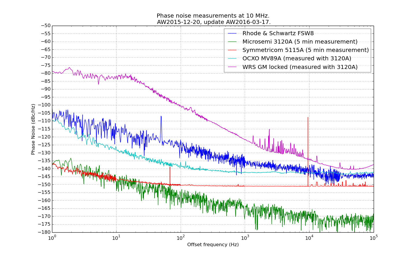
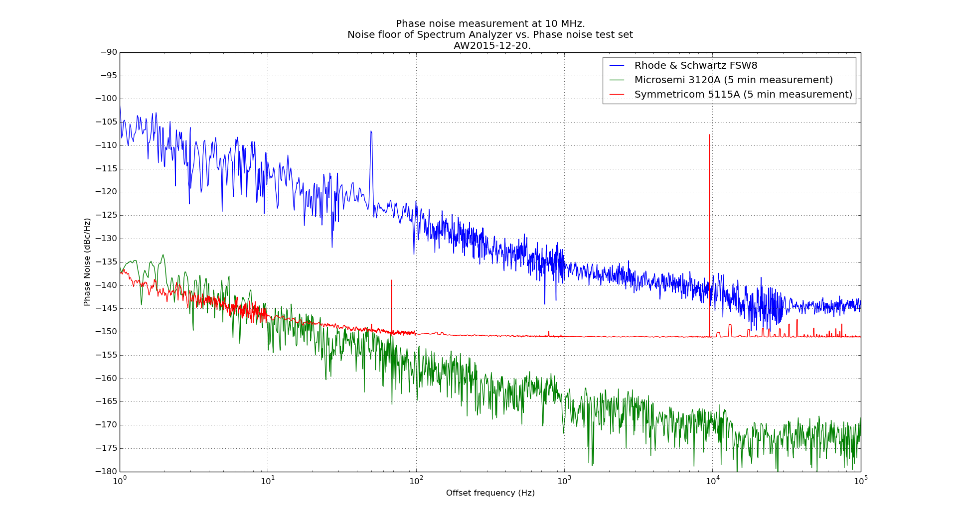
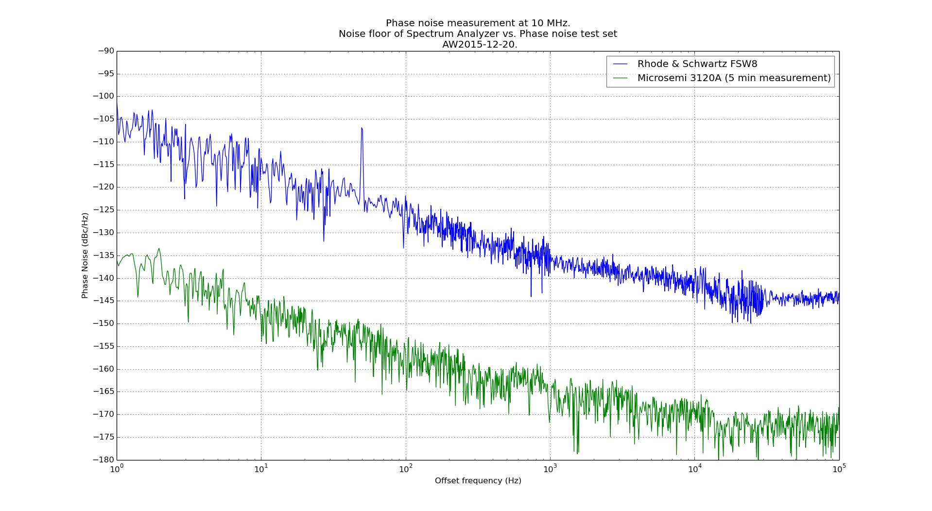
I updated my earlier picture with the noise-floor of three different phase-noise measurement setups. The picture now includes a typical good OCXO trace and the CLK2 10MHz output of a GM-locked White Rabbit Switch (v4.2 firmware).
Update 2016-01-14: Added noise floor of Symmetricom 5115A:
The question of using a general purpose Spectrum Analyzer vs. a dedicated phase noise test set for measuring phase noise came up on the EEVBlog forum. Here are two noise floors for 10 MHz phase noise measurements measured recently. One with a R&S FSW8 spectrum analyzer and the other with a Microsemi 3120A phase noise probe. The 3120A noise floor improves by maybe 10 dB in a longer duration measurement (e.g. hours instead of minutes). On the other hand the SA can measure phase noise out to at least 1MHz offset frequency and at any (I think?) carrier frequency up to several GHz.
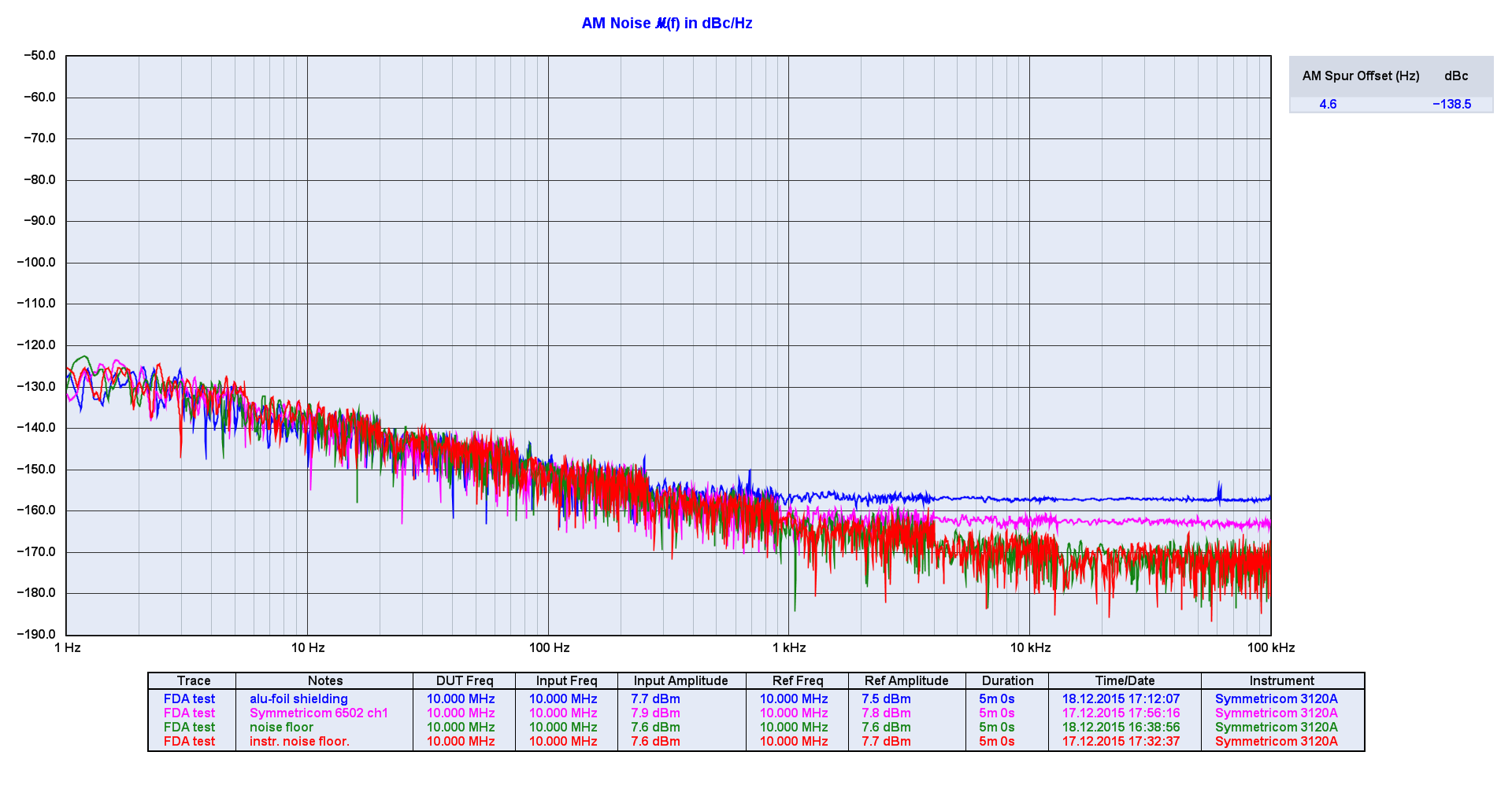
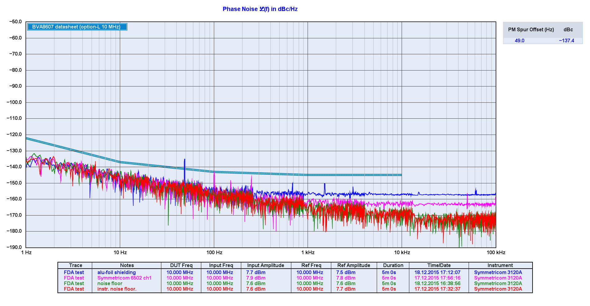
Update 2015-12-18: Things improved quite a lot by simply wrapping the board in aluminium foil!
The amplifier phase noise floor is now at around -156 dBc/Hz while the 6502 is at -163 dBc/Hz. The AM noise numbers are similar.
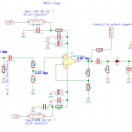
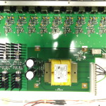
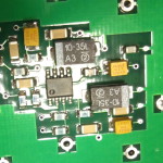
Original post 2015-12-17: I put together a first prototype (only one output channel) of my TADD-1 inspired frequency distribution amplifier. Preliminary schematic here.
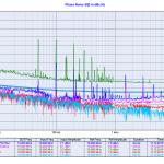
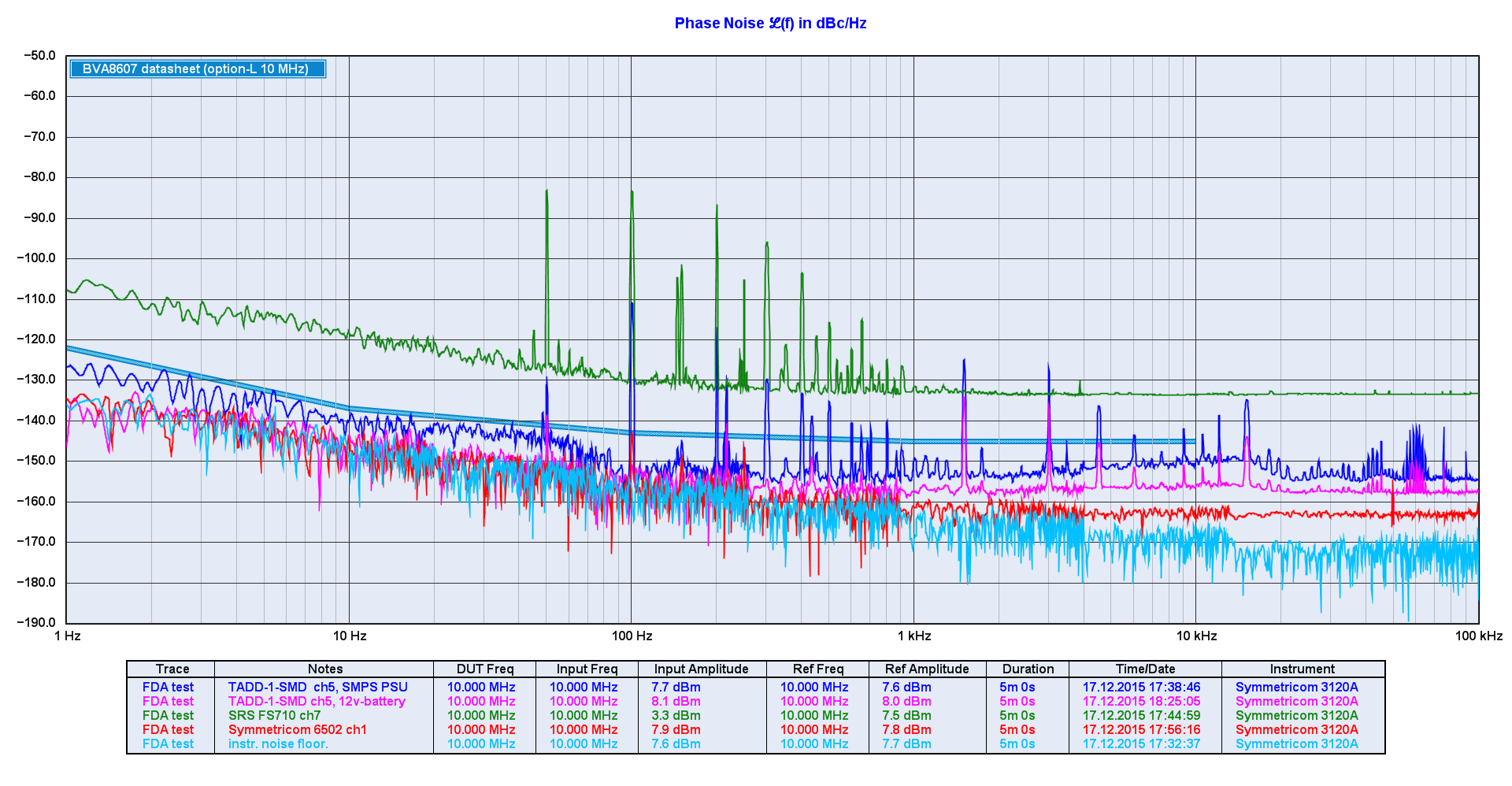
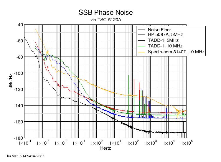
I compared the prototype board to two commercial distribution amplifiers: an SRS FS710 (quite awful) and a Symmetricom 6502 (very good). I also compared my new data with John Ackermann's measurements from 2007.
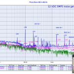
The new board showed ugly spurs at 50 Hz and harmonics using an el-cheapo wall-wart 12 VDC SMPS, so I also tried it with an "ultra-low noise DC-source" a.k.a 12 V lead-acid battery.
First distribution amplifier prototype. No soldermask. Only one output channel for now.
Comparing John Ackermann’s data from 2007 with my data.
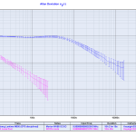
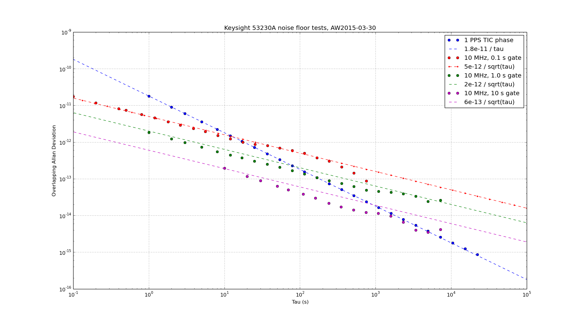
Allan deviation plot.
AM noise plot.
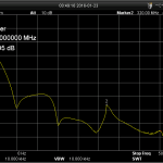
Phase noise of distribution amplifiers at 10 MHz.
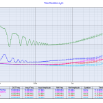
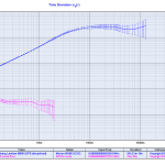
Time deviation plot.
Difference between 12 VDC SMPS “wall-wart” and 12 VDC battery.
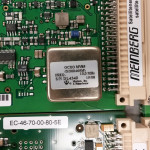
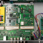
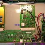
Here's a peek inside a Meinberg Lantime M600 PTP/NTP server. It follows the same modular design as the Lantime M300 with the GPS receiver on the right and the computer-board to the left. The new thing is a Time Stamping Unit (TSU) in the middle.
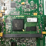
The TSU (by Toradex) seems to be built in a memory-stick form factor (SODIMM?) around a Marvell 88ap270m chip (PXA270 processor?). Maybe it's a Toradex Colibri PXZ270?
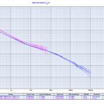
ADEV of GPS-disciplined MV85 OCXO. Shown with 53230A RCON-mode noise floor.
TDEV of GPS-disciplined MV85 OCXO suggesting a phase measurement resolution of a few nanoseconds.
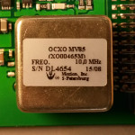
Morion MV85 OCXO on the GPS receiver board.
Modular design from left to right: Computer, Time Stamping Unit, GPS-reicever and OCXO, Power Supply.
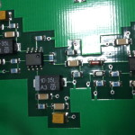
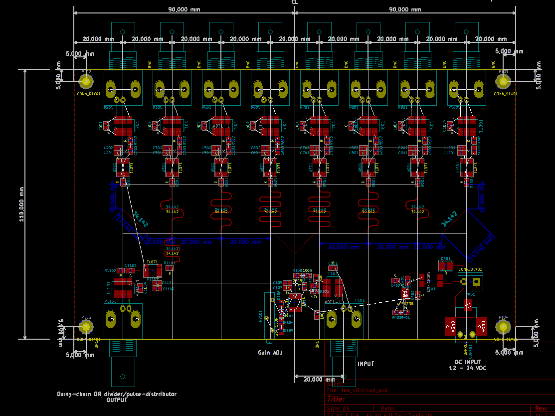
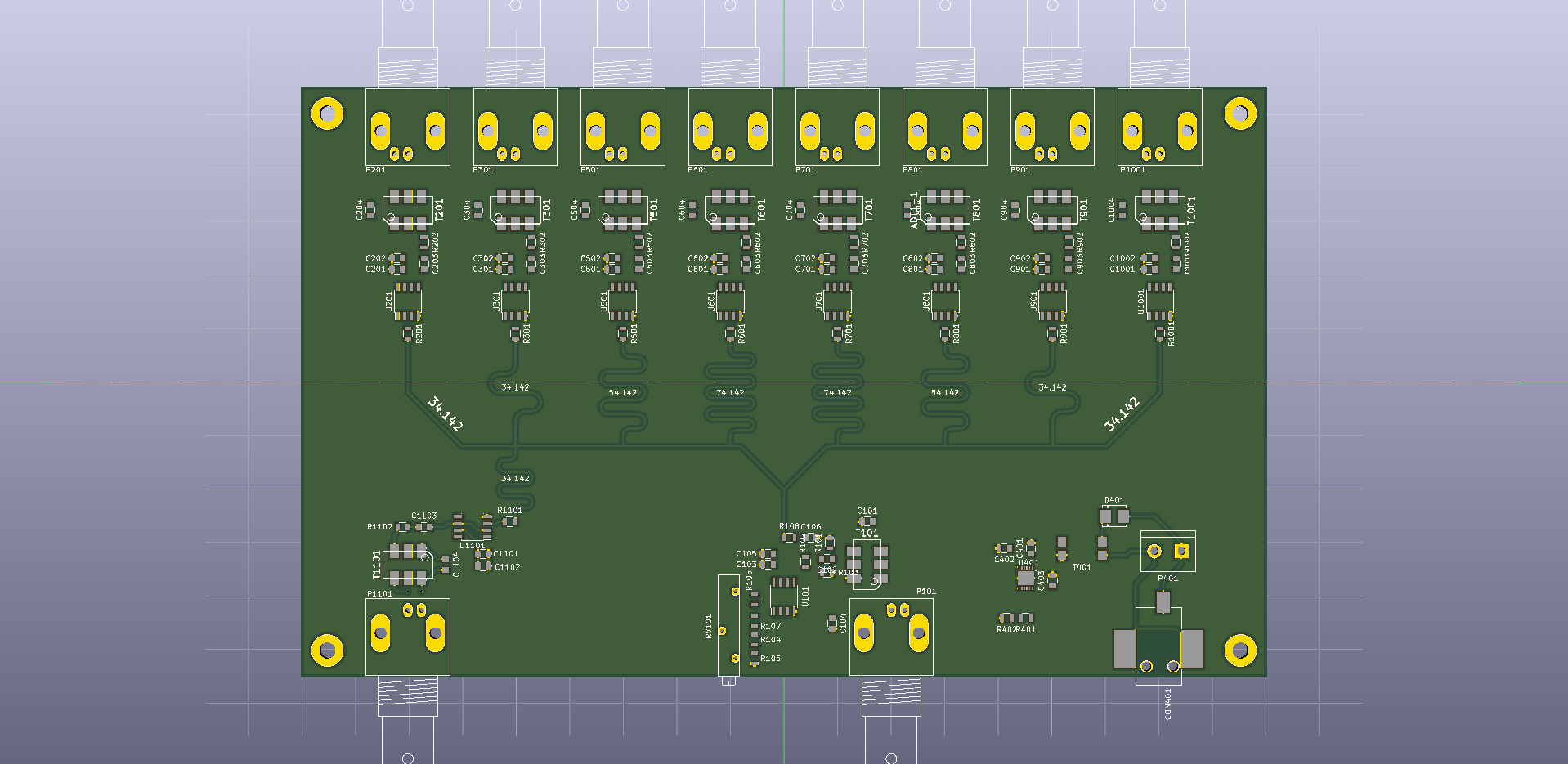
Here's a draft design for an SMD version of the TADD-1 frequency distribution amplifier. The plan is for a 2-sided 180 mm x 110 mm PCB. Two of these could be mounted side by side in a 1U 19" enclosure to give 2x8=16 outputs on the front panel. If a companion pulse distribution (1-PPS) board is built, the output at the back of this board can be used to drive a PICDIV on the pulse-distribution board. This gives 8 frequency outputs and 8 pulse outputs on a 1U 19" panel. The 2-pin connector at the DC-input can be used to power the other board in the same enclosure.
Comments? Suggestions?
What causes phase-noise (drift) below 1Hz offset frequency in this graph?
The original TADD-1 used a MAX477 and the update in 2007 used an AD8055. Are there newer and better op-amps?
We need a good low-noise linear regulator circuit (lower right corner). Suggestions? (what's inside an Abracon ABPSM-ULN-A?)
Following Dave's advice here: "Don't turn it on - take it apart!"
Meinberg Lantime M300 - Multi Reference NTP server. This server works as stratum-1 using a number of different input signals such as GPS, 1PPS, 10MHz, and IRIG/Timecode.
The loop time-constants seem to be very long, since the ADEV plot does not change much (at least not immediately) when connecting or disconnecting e.g. the 1PPS or 10MHz inputs. If I would be more patient I would measure it free-running and with all the different stratum-1 input signals for a few days each - that would maybe show some interesting things about how the internal OCXO is locked to the reference inputs. My assumption would be that IRIG would produce the worst ADEV, GPS second worst, 1PPS quite good, and the 10MHz input should produce an excellent ADEV with the shortest lock time-constant.
Lantime M300 10MHz output, free running ADEV.
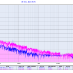
Lantime M300 10MHz output, phase noise.
Morion MV85 10MHz OCXO.
Overview of internal components. When did you last see a 1Gb CompactFlash card? 😉
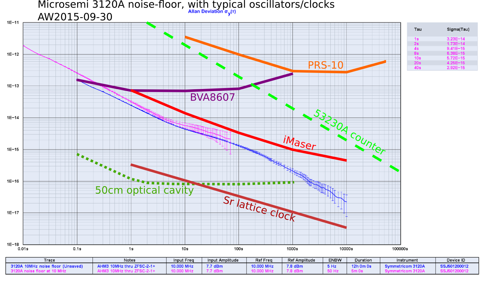
This was measured by taking a H-maser 10MHz signal (output from a frequency distribution amplifier) and splitting it in two for the 3120A REF and DUT channels with a ZFSC-2-1+ passive splitter.
The first measurement is with 50 Hz bandwidth and a duration of 5 minutes. The second measurement is at 5 Hz bandwidth and ran overnight for 12 hours.
Allan deviation
Amplitude noise
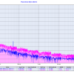
Phase noise
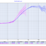
Time deviation
Here's the ADEV plot with some typical performance-curves added.
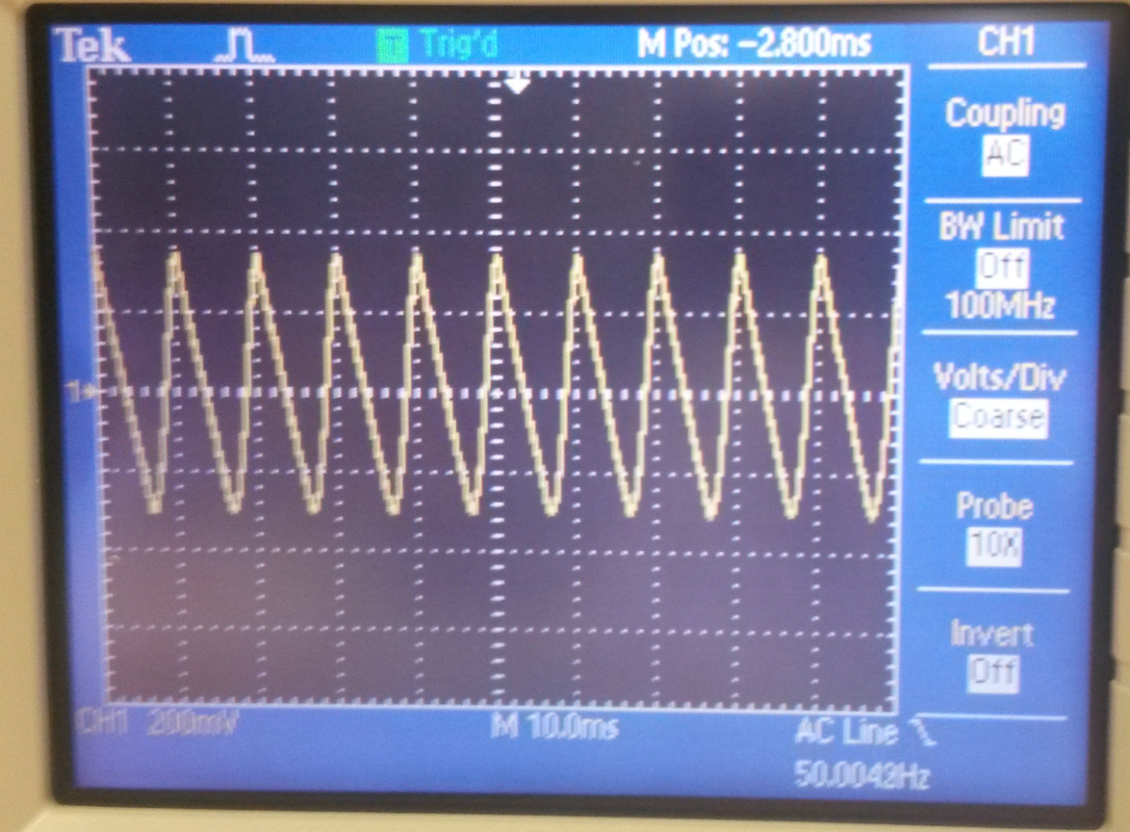
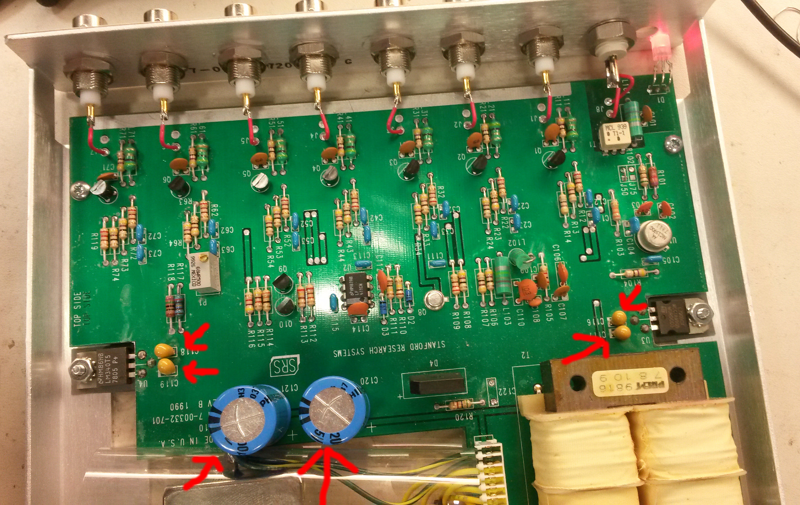
Update: changing the main electrolytic capacitors as well as the tantalum caps around the 7805/7905 voltage regulators did not help. There is still about 600 mVpp of ripple on the +/- 13.9 VDC inputs to the regulators.
600mVpp 100Hz sawtooth on +/-13.9VDC inputs to voltage regulators
I replaced the electrolytic capacitors after the diode-bridge, and also the tantalums just before and after the 7805/7905 voltage regulators.
Here's a noise measurement on an old second-hand SRS FS710 distribution amplifier. I wonder if the excessive noise at 50 Hz and harmonics is within spec or a result of old age?
Measurement setup: 10MHz signal to a Mini-Circuits ZFSC-2-1+ splitter, one branch to 3120A REF-input, the other branch to the FS710 input, and FS710 output1 to the 3120A DUT input. Noise floor was measured with the same setup but bypassing the FS710.

