Drop-Cutter toroid edge test

The basic CAM-algorithm called axial tool projection, or drop-cutter, works by dropping down a cutter along the z-axis, at a chosen (x,y) location, until we make contact with the CAD model. Since the CAD model consists of triangles, drop-cutter reduces to testing cutters against the triangle vertices, edges, and facets. The most advanced of the basic cutter shapes is the BullCutter, a.k.a. Toroidal cutter, a.k.a. Filleted endmill. On the other hand the most involved of the triangle-tests is the edge test. We thus conclude that the most complex code by far in drop-cutter is the torus edge test.

The opencamlib code that implements this is spread among a few files:

  • millingcutter.cpp translates/rotates the geometry into a "canonical" configuration with CL=(0,0), and the P1-P2 edge along the X-axis.
  • bullcutter.cpp creates the correct ellipse, calls the ellipse-solver, returns the result
  • ellipse.cpp ellipse geometry
  • ellipseposition.cpp represents a point along the perimeter of the ellipse
  • brent_zero.hpp has a general purpose root-finding algorithm

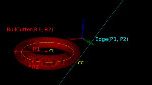
The special cases where we contact the flat bottom of the cutter, or the cylindrical shaft, are easy to deal with. So in the general case where we make contact with the toroid the geometry looks like this:

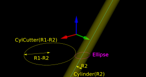
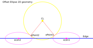
oe1_text

Here we've fixed the XY coordinates of the cutter location (CL) point, and we're using a filleted endmill of radius R1 with a corner radius of R2. In other words R1-R2 is the major radius and R2 is the minor radius of the Torus. The edge we are testing against is defined by two points P1 and P2 (not shown). The location of these points doesn't really matter, as we do the test against an infinite line through the points (at the end we check if CC is inside the P1-P2 edge). The z-coordinate of CL is the unknown we are after, and we also want the cutter contact point (CC).

There are many ways to solve this problem, but one is based on the offset ellipse. We first realize that dropping down an R2-minor-radius Torus against a zero-radius thin line is actually equivalent to dropping down a zero-minor-radius Torus (a circle or 'ring' or CylCutter) against a R2-radius edge (the edge expanded to an R2-radius cylinder). If we now move into the 2D XY plane of this circle and slice the R2-radius cylinder we get an ellipse:

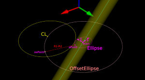
oe3text

The circle and ellipse share a common virtual cutter contact point (VCC). At this point the tangents of both curves match, and since the point lies on the R1-R2 circle its distance to CL is exactly R1-R2. In order to find VCC we choose a point along the perimeter of the ellipse (an ellipse-point or ePoint), find out the normal direction, and go a distance R1-R2 along the normal. We arrive at an offset-ellipse point (oePoint), and if we slide the ePoint around the ellipse, the oePoint traces out an offset ellipse.

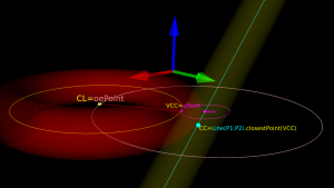
oe4_text

Now for the shocking news: an offset-ellipse doesn't have any mathematically convenient representation that helps us solve this!
Instead we must numerically find the best ePoint such that the oePoint coincides with CL. Like so:

oe5text

Once we've found the correct ePoint, this locates the ellipse along the edge and the Z-axis - and thus CL and the cutter . If we go back to looking at the Torus it is obvious that the real CC point is now the point on the P1-P2 line that is closest to VCC.

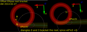
In order to run Brent's root finding algorithm we must first bracket the root. The error we are minimizing is the difference in Y-coordinate between the oePoint and the CL point. It turns out that oePoints calculated for diangles of 0 and 3 bracket the root. Diangle 0 corresponds to the offset normal aligned with the X-axis, and diangle 3 to the offset normal  aligned with the Y-axis:

oe_bracket_drawing


Finally a clarifying drawing in 2D. The ellipse center is constrained to lie on the edge, which is aligned with the X-axis, and thus we know the Y-coordinate of the ellipse center. What we get out of the 2D computation is actually the X-coordinate of the ellipse center. In fact we get two solutions, because there are two ePoints that match our requirement that the oePoint should coincide with CL:

oe_2d_drawing


Once the ellipse center is known in the XY plane, we can project onto the Edge and find the Z-coordinate. In drop-cutter we obviously approach everything from above, so between the two potential solutions we choose the one with a higher z-coordinate.

The two ePoint solutions have a geometric meaning. One corresponds to a contact between the Torus and the Edge on the underside of the Torus, while the other solution corresponds to a contact point on the topside of the Torus:

I wonder how this is done in the recently released pycam++?
Opencamlib cutter shapes

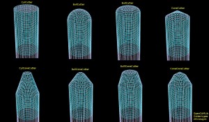
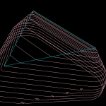
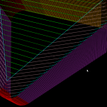
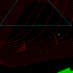
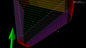
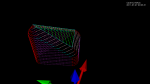
If you calculate toolpaths around a very narrow and 'pointy' triangle you will get toolpaths in the shape of the inverse cutter - the "Inverse Tool Offset". Here I've plotted the basic operations, in red/blue drop-cutter which drops the cutter down along the z-axis until it contacts the triangle, and in cyan waterlines which are the results of a push-cutter operation that pushes the cutter at constant z-height along the x/y axis into contact with the triangle.

There are four basic cutter shapes: (1) Cylinder, (2) Sphere('Ball'), (3) Toroid('Bull'), and (4) Cone. The triangle contact can be divided into tests for contact with (a) the three vertices of the triangle, (b) the facet of the triangle, and (c) the three edges of the triangle. That's 4x3 = 12 contact/collision-test functions that have to be written (a few, particularly the facet-tests, can be combined into one base-class method).

Once the basic cutter shapes work it is possible to combine them through CompositeCutter. The bottom row shows cutters with a central part corresponding to the top row of cutters, and a conical outer part.

The point of this exercise is of course not only to plot inverse-tool-shapes, but to be able to calculate toolpaths for these and other CompositeCutter tool shapes. This will become more interesting if/when the cutting-simulation starts working and it will be possible to compare for example surface-finish vs. cutting-time of a BallCutter operation vs. a BullCutter operation.

Comparing waterlines

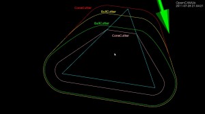
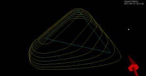
Here's a picture which compares the waterline toolpath for different cutters around a single triangle (cyan). The outermost path (red) is for a cylindrical cutter where we always make contact with either the shaft of the cutter or the circular rim/end of the cutter. Next is the yellow line for the toroidal or BullCutter, followed by the green line for a spherical or BallCutter. The innermost waterline (pink) is for a conical ConeCutter.

waterline_compare

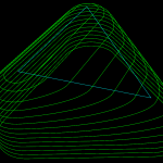
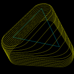
Here are some more waterlines at different heights. This exercise has uncovered at least two new bugs with CylCutter and ConeCutter! The CylCutter seems to fail when asking for a waterline at z=0.0, so that might hint at where the problem is. I'm not sure what is causing the jagged shape with ConeCutter.

Update: The cl-points for conecutter look right, so there must be something strange going on with the weave??

conecutter_looks_ok

Cone-cutter waterlines

I'm not sure why it has taken so long to get the push-cutter methods for ConeCutter written. You would think that the cylindrical, spherical, or toroidal cases are at least as hard. Somehow I have just avoided working on the cone-cutter...

The easy part is as usual contacts between the cutter and the vertices of a triangle - these are shown as red dots. Contact with the facet of the triangle can be made in two ways (1) by the tip of the cone, or (2) by the circular base of the cone, when the facet is steeper than the cone. These are shown in green.

The more involved case is contacts with the edge of the triangle. There are again two cases: We can make contact with the circular base of the cone (cyan dots), or we can make contact with the actual conical part of the cutter (pink dots).
conecutter_00034

Here is an animation that gives the code a workout. Note how the color of the contact-points changes depending both on what part of the triangle we are making contact with and on what part of the cutter is making the contact.

I have now used github for a while, and will probably merge the conecutter feature-branch into master very soon. Almost as soon as I tried github google-code also started supporting git, but possibly the forking and social aspects of github make a switch worthwhile anyway.

There are some interesting developments on the higher level Waterline/Weave algorithm also, which will reduce the memory-consumption of the algorithm from N*N to N+N (where N is the number of Fibers). This will hopefully make Waterline more useful as now many people have been running out of RAM or just seen sudden crashes. Stay tuned...

Weave notes

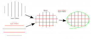
As noted before, the waterline operation consists of radial cutter projection ("push cutter") along fibers/dexels, followed by a weave/grid construction, and contouring to produce the final toolpath. Like so:

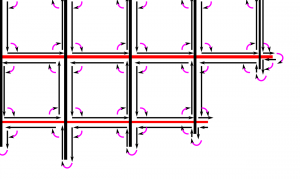
The new Weave2 class builds up a half-edge diagram in a smart way, maintaining "next" and "previous" pointers for each edge, so that the green toolpath loop can easily be found by traversing from one CL-point to the next simply following the "next" pointer:


(The magenta arrows are "next" pointers which point from one edge to the next)

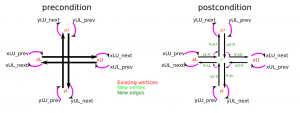
The main part of the algorithm looks at one X-fiber (from xL to xU) and one Y-fiber (from yL to yU) at a time and inserts a new internal vertex (v) into the diagram, while maintaining the existing "next" and "prev" pointers.

I didn't come up with any elegant object-oriented scheme that would do this nicely, so the build() function in the code just peeks and pokes and updates all of the 24 pointers in a brute-force kind of style.

I suspect that the O(n^2) time-complexity is optimal, since with n X-fibers and n Y-fibers there will be roughly n*ninternal vertices in the grid, and they all have to be processed (?unless we can prune the grid and ignore internal areas and focus on the edge of the weave?).

Faster Waterline

I've written a new Weave class for opencamlib which makes the waterline operation faster.

The first test-case is a single triangle, and we calculate a number of waterlines at different z-heights using a ball-cutter:

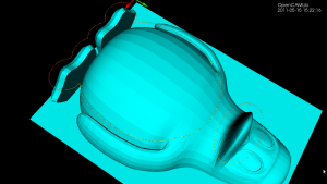
The second test-case is the Tux model where we calculate a single waterline at some z-height. Note how using the chosen ball-cutter at this particular height the waterline splits into two separate loops.

(the yellow line is a plain waterline and the red line is an adaptive Waterline, but that's not important here)

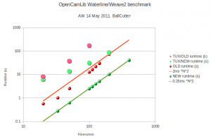
Here is the runtime data. The smaller symbols show results from the one-triangle test-case. The old algorithm(red data points and line) seems to be slower than O(N^2), with a pre-factor of about 2 milliseconds. The time data for the new algorithm (green) fits an O(N^2) line better and has an almost 10-fold faster pre-factor of around 0.25 ms.

The speedup for the Tux model (large symbols) is even greater. With the old algorithm the slope of the data points (pink) looks much worse than N^2 and runtimes quickly reach a minute or more. With the new algorithm (big light green symbols) the runtime stays under 100s even at 200 fibers/mm.

This speedup was achieved by building a weave which is a directed half-edge graph, instead of the old undirected graph. The old algorithm first used connected_components (time complexity O(V + E)) to split the weave into its connected components. For each component a planar embedding was then constructed (time complexity ??), and the toolpath loop extracted with planar_face_traversal (time complexity O(V+E)).

In the new Weave, each edge has a "next" pointer pointing to the next edge of the face. This means we can extract the toolpath loop by following the "next" pointer until we find the next CL-point. Effectively the planar embedding is now contained in the graph datastructure and does not have to be computed separately. This also saves work since we don't have to traverse faces which do not produce toolpaths. This new solution to the weave point-order problemdeserves its own post in the near future - stay tuned...

Cutter shapes

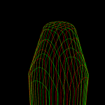
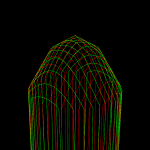
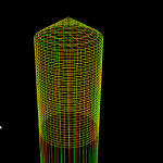
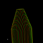
The four basic cutter shapes in opencamlib are CylCutter (cylindrical or flat-endmill), BallCutter (spherical), BullCutter (toroidal, filleted-endmill), and ConeCutter (cone, "v"-cutter).
With CompositeCutter it is then possible to combine these four into sensible combinations (such as the APT-tool). Below the combinations where the outer part of the cutter is conical, and the inner part is one of the four basic shapes. They are named CylConeCutter, BallConeCutter, BullConeCutter, and ConeConeCutter.
The general edge-push function for the cone shape isn't done yet, so there are no waterlines (except in special cases) for the cone-shape.


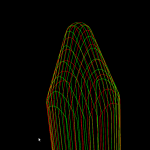
These inverse-tool-offset ("ITO") type images were drawn by using drop-cutter (red and green) and waterline (yellow) on a very narrow and tall triangle, so the toolpath shape looks like the inverted cutter.

VD algorithm animation

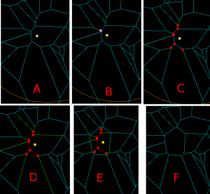
Some notes on the Sugihara&Iri 1994 topology-based algorithm for incremental construction of the voronoi diagram for point sites.

(A) We start with initial VD for point sites that have already been inserted. We want to insert a new site, shown as a yellow sphere.

(B) We then find the VD face to which the new vertex belongs. Among the vertices that bound this face we search for a seed-vertex, shown in pink. This is the vertex that is closest to the new generator.

(C) From the seed vertex, we search for more vertices that should be deleted(red). The vertices should form a tree (a connected, acyclic graph). Vertices that are closer to the new site than to any other site should be deleted. However due to floating-point errors it's not possible to blindly rely on an inCircle() predicate for finding the delete-tree. It's necessary to also enforce the correct topology, namely (i) the delete-vertices should form a tree, and (ii) for any incident face, the delete-vertices are connected. This ensures that no old face of the graph is deleted or split in two.

(D) Identify the edges to be deleted (red), and edges on which we need to generate new vertices (green).

(E) Generate new vertices on the green edges, and connect all the new vertices by new edges. These new edges form a new face corresponding to the newly inserted site.

(F) Remove the red/delete-vertices and edges. We are left with what we want: the VD of all the old sites and the new site.

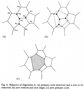
Another picture from the original 1994 paper. The new site is not shown, but by some process we have found the delete-tree (u1,u2,u3,u4) shown as solid dots. New vertices are then generated on the "in-out" edges (u2-u10, u2-u5, u3-u6, u3-u7, u4-u8, u4-u9), shown as unfilled dots. The unfilled dots are connected with new edges (dashed lines) that form the new facet (shaded area). Image borrowed from: Sugihara&Iri 1994.

Here is an animation of the algorithm at work when inserting about 100 random points: