Kasuyasu Hamada has made a lot of progress with my earlier cutsim work. Code is on github: https://github.com/KASUYASU/cutsim
For a historical time-line see the cutsim tag.
Kasuyasu Hamada has made a lot of progress with my earlier cutsim work. Code is on github: https://github.com/KASUYASU/cutsim
For a historical time-line see the cutsim tag.
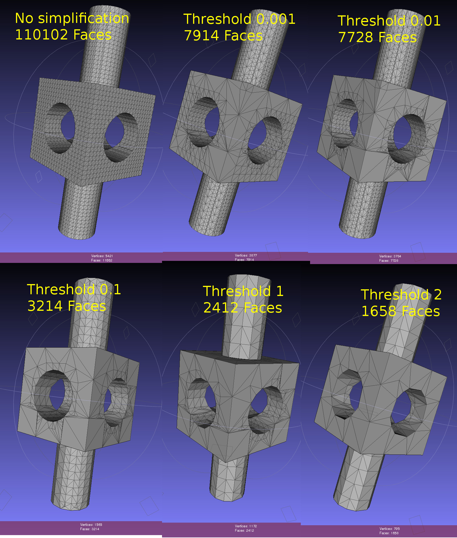
Dual contouring uses a quadratic-error-function (QEF) to position a vertex inside each octree-node (cube) where the implicit distance-field that defines our geometry changes sign. The vertex is positioned so that the QEF is minimized. This allows for an octree simplification strategy where we combine all the QEFs of the eight child-nodes, and see if we can replace the eight vertices they define with with a single vertex one level up in the octree.
This image shows the dual contouring code run on the same input data with various levels of simplification. Even a small threshold value of 0.001 reduces the number of triangles more than ten-fold. Too large a threshold produces jagged edges. Note that dual contouring of the original dataset where each leaf-node is at the same (maximal) depth of the tree produces only quad polygon output. When we simplify and collapse some nodes to non-maximal depth the algorithm also produces triangles - where a collapsed node is adjacent to nodes deeper in the tree.
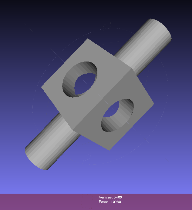
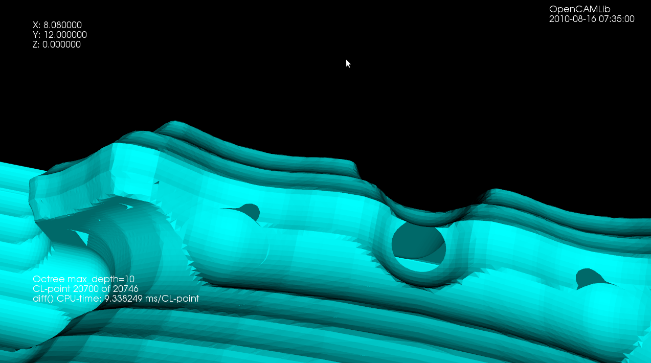
Here's an image from the CNC-milling simulator I am working on. It stores a signed distance field in an adaptively subdivided octree. To render a surface of the stock we then run an isosurface extraction algorithm. The most well-known of these is the Marching Cubes (MC) algorithm, used here also. One problem with MC is that it doesn't preserve fine detail (like sharp edges) very well, and many times there are also gaps or cracks in the surface. Both of these problems are visible below.
From about 2000 onward there are a number of papers that try to improve on MC. The most promising seems to be Dual Contouring, by Tao Ju. There is both c++ and Java LGPL code for DC on sourceforge, and I made some slight changes to make it compile with cmake on Ubuntu: https://github.com/aewallin/dualcontouring
The output PLY file can be viewed with meshlab:
So far so good. Now the task is to either rewrite my octree + boolean CSG operations code to use the data structure used in the DC code, or vice versa, change the DC code to use my datastructure.
Here's a simple test program using LibQGLViewer (screen capture with xvidcap). The vertex array and the index array that OpenGL draws (using glDrawElements) are held in a GLData class which holds a mutex. The Viewer class locks the mutex while drawing, and the worker-thread locks the mutex while updating the data. Here the worker task re-positions the original vertex position, signals the Viewer to draw, and then sleeps for 40 ms. When we don't rotate or zoom with the mouse the frame-rate should thus be 25 Hz. Rotating or zooming causes more frequent re-draws and a higher frame-rate.
To gain any real benefit on a multi-core machine I think the worker thread needs to work on a 'dirty' copy of the data, and we only lock the mutex for a minimal time while swapping in the updated data for the real data. Anyone have any good example code for this? Both a case where the worker produces new data at a slow rate (slower than Viewer re-draws), and at a faster rate should be handled.
Here's an UML(ish) diagram drawn with dia:

Code.
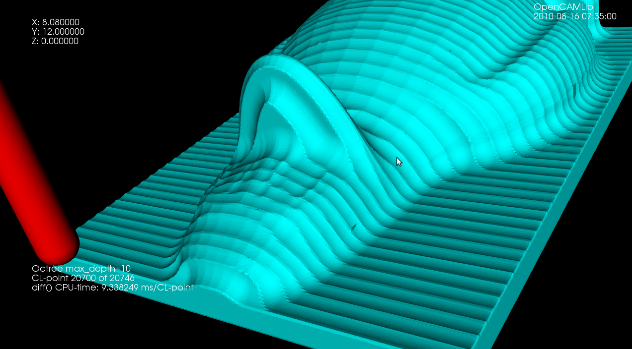
Based on Mark Pictor's cam-occ work I've been able to use the emc2 g-code interpreter 'rs274' binary that gets built during an emc2-build. It reads g-code files and outputs 'canonical' motion commands (see e.g. "The NIST RS274/NGC Interpreter - Version 3"). I'm positioning the tool at densely sampled points along each move, and subtracting it from the stock (see Yau and Yau) . The stock model is a distance field stored in an adaptive octree (see Frisken and Frisken).
This is very experimental: There's one kind of stock and one kind of tool, namely spherical!, The stock and tool sizes and colors are hard-coded, There's only one thread which means the UI becomes unresponsive and greyed-out during about 57s of processing. It's slow, 57s for a fairly simple 20-line g-code file. We assume hard-coded paths for the 'rs274' binary and the emc2 tooltable-file.

I've looked at set-operations (union, difference, intersection) for octrees again. Previously I tried it with linear-octrees and visualization with python and VTK. Now I'm using a traditional pointer-based octree data-structure, and drawing with OpenGL VBOs. With the addition of a g-code interpreter, a user-interface, and an isosurface extraction algorithm (such as marching-cubes) this should converge towards a milling/turning/3d-printing cutting-simulation sometime soon...
References: Frisken2000 and Frisken2006.

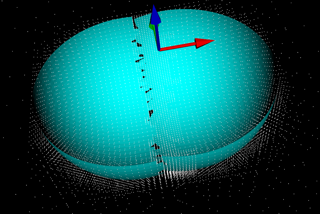
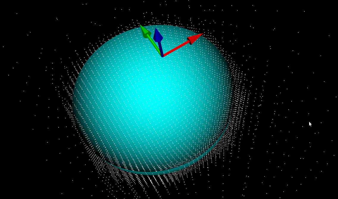
Update: this figure shows the numbering of vertices(red), edges(green), and faces(blue). The arrows show the direction of the X-(red), Y-(green), and Z-axes(blue).

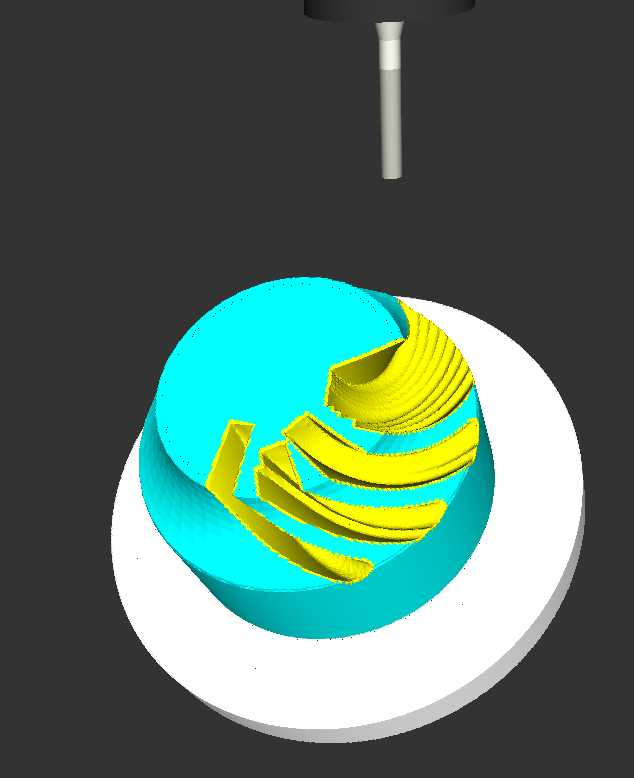
Here the sides of the cube are not generated with Marching-Cubes, they are just extracted directly from the octree. Nodes are subdivided whenever the signed distance-field of the cutter indicates that the surface is contained within the node, i.e. the distance-field evaluates to both positive and negative at the eight fourvertices of a node. This apparently leads to transient holes in the surface when the cutter is just about to enter a coarse node which hasn't been subdivided very far yet. It should be possible to adjust the subdivision criterion so that the octree 'anticipates' the cutter slightly and subdivides ahead of the actual cutter surface.
The speed of the new cutting-simulation code makes it possible to run it at a higher resolution than before. That makes the surfaces look smooth and nice. Alas, some problems still remain with holes in the fabric of reality mystically appearing and disappearing .
There is an edge-flipping paper by Kobbelt et al. from 2001 which improves the jagged/aliased look of sharp edges.
Update: Kobbelt provides a LGPLv2 licensed sample-implementation of the algorithm here: http://www-i8.informatik.rwth-aachen.de/index.php?id=17
This is my second attempt at a machining simulation where a moving milling tool cuts away voxels from the stock material. To save space an octree data structure is used to store the voxels, and to produce a nice looking surface you store the signed distance to the exact surface in each vertex of the octree. You then use marching-cubes to extract triangles for a distance=0 isosurface in order to draw the stock.
Unlike my first attempt, this works well enough to warrant further experiments (on the to-do list are: differently shaped tools, colouring triangles based on which tool cut the voxel, lathe operations, material removal-rate, etc.). It should be straightforward to hook this up to the EMC2 G-code interpreter so that any G-code, not just densely sampled CL-points from OCL, can be simulated. You could also flip the sign of all the numbers, and simulate an additive process, like 3D printing (reprap / makerbot).
This approach to machining simulation is described in a 2005 paper by Yau, Tsou, and Tong.
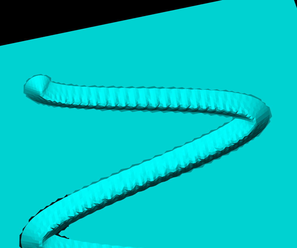
Update 3: this leads slowly towards a better and faster cutting simulation. Here's an example with Tux:

Update2: this looks slightly better now (a ball translated in a few steps towards the right). Image and c++ code by fellow OCLer Jiang from China.

Update: in a cutting simulation the stock is updated by removing voxels which fall inside the cutter. Here I'm trying it with a spherical shape positioned at (0,0), and then moved slightly along the X-axis. The white dots are corners of octree nodes, and the cyan triangles are produced by marching cubes. It works quite well, but on the border between the two cutter instances the distance-field is somehow wrong, and marching-cubes doesn't come up with the right triangles, leaving gaps instead.
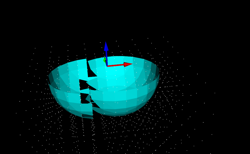
Earlier I was building an octree volume-representation of a shape using a simple bool isInside(Point p) predicate function to determine which cubes are in and which are out. If instead a distance-function double distance(Point p) which is negative inside the volume, zero exactly on the surface, and positive outside, is used, then the Marching Cubes algorithm (this is a better explanation, someone should make the wikipedia page as good!) can be used to triangulate the octree. This leads to much more visually pleasing results at reasonable maximum tree-depths.
The same Hong-Tzong Yau of Taiwan who wrote a very reasonable drop-cutter paper in 2004 has more recently come out with a 2009 paper on cutting simulation using an octree and Marching Cubes.