Equatorial Wedge - Drawings

By popular demand, drawings for the iOptron MiniTower Equatorial Wedge project I completed in 2010 August-September (see old blog posts: base, top, side, knobs)

Here's how the wedge looks like. It consists of a fixed plate that attaches to the tripod, two fixed side plates that bolt to the bottom plate, and a moving plate that tilts about 10 degrees. The wedge is designed so that the centre of gravity of the MiniTower is positioned straight over the middle of the tripod.

The extra 6mm hole in the side-plates is for an M6 threaded rod through the mount which should provide precise azimuth-adjustment. I did not complete this feature (for example a rotating nut in the fixed plate would be needed).

minitower_wedge

PDF drawings:

Dobson-mount progress

About 2 hours more work on the triangular base for the telescope dobson-mount.


Here I have added one more profile in the middle of the triangle which holds an 11mm diameter steel pin, around which the upper platform will rotate. Roughly 30mm high acetal plastic cylinders at the midpoints of the triangle-sides support the upper platform and will hopefully provide the right amount of friction. Too much and it will be hard to move the telescope, too little and it won't stay aimed at a particular target.


This is the upper platform, a piece of oak-board. The steel pin fits in a brass-fitting which is bolted to the center of the board.


This is how the two pieces fit together (upside down). The oak-board will rotate around the steel pin while resting on the three acetal posts.

To be continued...

Triangular base for Dobson-mount

I made this triangular base for the telescope Dobson-mount we are building. It has three ca 640mm long 25mm-by-25mm aluminium profiles, cut at a 30-degree angle to make an equilateral triangle. It is held together with tapered pieces of 100mm wide 10mm thick aluminium bar that attach to the T-groove of the profile with M6 screws. Each corner has an adjustable foot.

The mount that goes on top of this triangle is also from 25-25 alu-profile:

Stay tuned for hopefully some lunar and/or planetary images when this project is done.

Building a Telescope, a drama in 21 Acts

Act 0 (anecdotal): In which the Builders catch the Aperture Fever and start to dream of mirrors large.

Act 1 (2008 July 22): In which the Builders acquire the Glass and first smell the Carborundum.

Act 2 (2008 July 30): In which the Glass is bevelled.

Act 3 (2008 August 1): In which the Builders observe a partial solar-eclipse.

Act 4 (2008 August 4): In which, after much work, the sagitta deepens to 2 mm.

Act 5 (2008 September 1): Birth of the pitch-lap.

Act 6 (2008 September 4): In which polishing begins and an early Ronchi-test is performed.

Act 7 (2008 September 28): In which the Focault-test is tried but the Builders yearn for something more quantitative.

Act 8 (2008 November 6): (tragic) In which a secondary-holder is turned on the New Lathe - only to be abandoned later.

Act 9 (2008 November 7): In which the builders cook-up a Bath Interferometer around a HeNe-laser.

Act 10 (2008 November 8 ): In which Interferograms are first photographed.

Act 11 (2008 November 18): In which the Builders inhale an inordinate amount of saw-dust and the Tube is born.

Act 12 (2008 December 2): In which the Interferometer's younger sibling is born.

Act 13 (2008 December 6): In which polishing continues.

Act 14 (2008 December 7): In which the Glass is polished spherical

Act 15 (2009 January 17): In which the Glass is figured to its final parabolic shape.

Act 16 (2009 January 17): In which the polishing tools are presented and make their exit.

Act 17 (2009 March 22): In which the Builders travel to a Big Telescope and preach of Interferometry to crowds.

Act 18 (2009 April 9): Birth of the Mirror Mount.

Act 19 (2009 June 12): In which the Tube acquires a colour reminiscent of much nobler tree-species.

Act  20 (2009 June 14): In which the Epoxy cures too fast and the Builders curse.

Act 21 (2009 July 2): (triumphant!) In which the focuser and spider are aquainted with the Tube, and the First Light is seen.

First Light!

scope

After 11 months in the making, July 2nd 2009 will be the historical date to remember when our 240 mm Newtonian saw First Light! July is not dark at all in Finland, but that didn't prevent us from setting up in the back-yard to have a look at the moon. Predictably the clouds soon rolled in, and the first light picture shows trees. Apologies for the poor quality, a snapshot with my N95 phone-camera through the eyepiece:

firstlight

Nevertheless, spirits were high as we earlier during the day with doubts in our minds had bravely drilled holes in the pristine wood-tube for the focuser and the 2ndary-spider. We were not 100% sure that the image would be nice or the focus-plane at the correct position - but everything seems to have turned out OK!

rings

This picture shows the 300 mm telescope-rings. They are now quite close together and we plan on making a wider support for them. We needed to add two layers of felt-cloth under them to get a nice fit. This scope is much heavier than the 80ED, and it's immediately clear that an EQ6-class mount is not overkill at all.

focuser

The 2-speed Crayford focuser with a 2" to 1.25" converter and an 8-24 mm click-stop zoom eyepiece. The grey ring around the scope is a 40 mm glassfiber band which was added to both ends of the tube as reinforcement. Two bolts that hold the spider in place are visible, one under the focuser and one just above the black fine-focus wheel.

2ndary

The front end of the tube with the spider holding the secondary mirror. The inside of the tube was spray-painted black once, but we may still improve on that later.

inside

A look inside the tube. At the bottom we see the parabolic 240 mm primary mirror,  still uncoated, so it only reflects about 4 % of incoming light. Through the right edge of the mirror the mirror-mount and the collimation bolts are visible. An image of the secondary mirror is visible to the left.

mirrormount

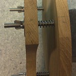
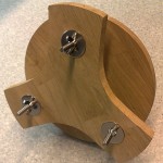
The back-end of the tube holds the primary mirror mount. This consists of two wooden boards, one bolted to the tube with three L-shaped fittings, and the other 'floating' on top supported by three spring-loaded collimation bolts. The three wing-nuts are used for collimation.

mirrormount2

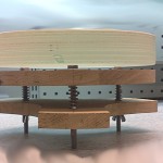
Another view of the back end of the scope which shows the glassfiber reinforcement, and big washers used to spread the load of the primary mirror mount.

Exothermic Epoxy

exotherm

When epoxy cures it releases heat in an exothermic reaction. I was adding some glass-fibre reinforcement to the telescope tube and mixed 140 g of L285 epoxy into an ordinary plastic cup. I got about half-way through the job when I noticed the cup heating up. I tried putting it in a cold water-bath, but it was too late by then... It quickly got very hot and all of it cured instantly! At room temperature this resin should have a 60 min pot-life, but now it cured in about 5 minutes. Not much harm done, but I understand these things can cause fires and all kinds of trouble when people deal with kg or tens of kg amounts.

Note to self: 100 g or more of L285 needs to be mixed in a shallow container with lots of surface-area which provides cooling. RTFM.

Does anyone else have pictures or stories about exothermic melt-downs?

Telescope Tube Painted

12062009958

The mirror has been figured and ready for some time now, but we've been so busy with other things that the telescope hasn't been finished. Now the plan is to assemble the mirror-cell, mount the 2ndary, and install the focuser so we can do some initial star-testing before aluminizing the mirror. Nice images of the moon and planets (Saturn, Jupiter) should be doable even though it's summer.

Mirror mount

The mirror is now parabolized to better than 1/18-wave RMS, so we are assembling the telescope to star-test it prior aluminizing the mirror. If and when everything looks OK through the scope we will send the mirror to be aluminized.

We came up with this mirror holder out of ca 20mm thick oak board. There are three M8 screws that support the mirror cell. Springs push it upwards, and the wing-nuts used for collimation pull down. It's all going to be attached to the wooden tube by three L-brackets.

Polishing tools

A few pictures and some notes on the polishing tools which we've used for the 240mm F/6 mirror for the Newtonian telescope we are making.

This is the full-size pitch-lap on top of the mirror. It's important to have good contact between the tool and the mirror at all times, so the pitch is pressed to conform to the mirror before each polishing sessions. This can be done either at room temperature, called cold-pressing, or by first heating the pitch-lap and the mirror in e.g. hot water, which is called hot-pressing.

We've usually hot-pressed the lap just after pouring it, and each time we have had to re-open the channels. The best way to open the channels we've found is with a saw - seems to work nicer and cleaner than with a sharp knife. When the lap has good contact with the mirror only cold-pressing is required before each polishing session. The image shows cold-pressing with a 20 kg weight on top of the tool, perhaps a bit on the heavy side.

This is the smaller weight, about 5.5 kg, we use on top of the tool when polishing. There's a significant difference in the speed of polishing with and without this weight. At first we did about 10 hours of polishing without a weight, but I'm sure this time could have been cut in half by use of this weight (or something slightly heavier). Ideally the weight should be evenly distributed over the mirror/tool, a steel disk of the same diameter would be good. But we haven't noticed any significant distortion of the mirror or tool with this smaller lead-weight.


When figuring the mirror from a sphere to a paraboloid this smaller 60% tool is used. Here it's cold-pressed against the mirror. Since this is an F/6 mirror the correct paraboloid shape is very close to the spherical shape that the mirror has at the end of polishing. We've found about 50 minutes of work with this tool is enough.