Category: CNC
VD shapes
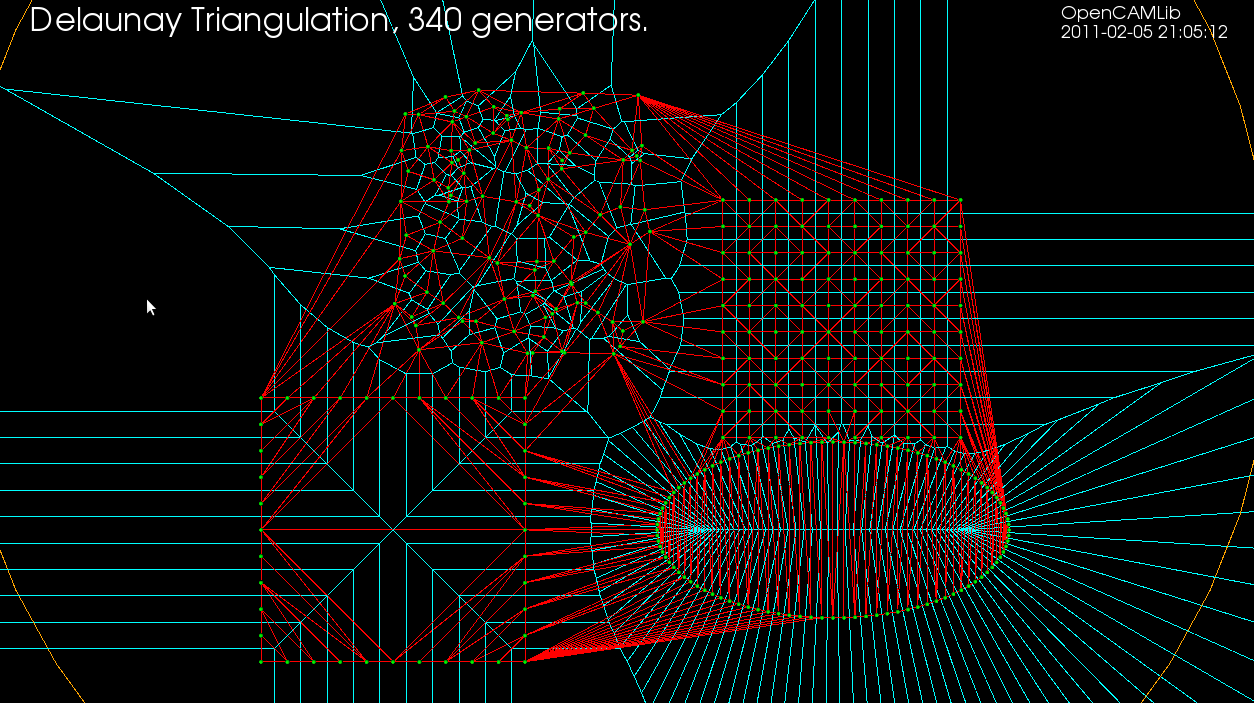
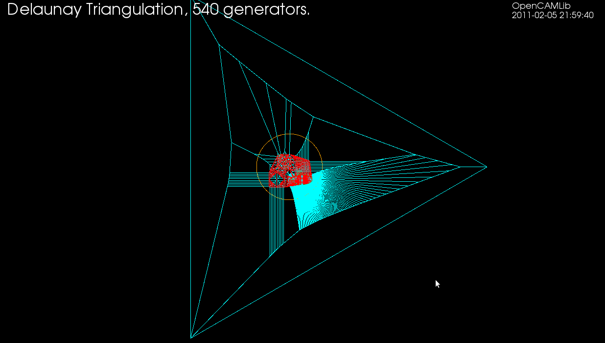
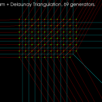
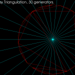
Note how the Delaunay triangulation (in red) is not correct. The outside of true Delaunay triangulation should form the convex hull of the input points, which is clearly not the case here(see how the red lines around the ellipse-shape are not tangents). What's going wrong? It has to do with how the algorithm avoids infinite or unbounded voronoi-edges. Before any real input generator points are inserted we start with three special generator vertices and the corresponding vd. A zoomed out view is shown below. If the cyan vd edges extending outward from the ellipse would stretch out to infinity then we would indeed recover the true Delaunay triangulation. The Voronoi diagram should however be correct inside the orange circle. I'm not sure how the true Delaunay triangulation could constructed with this algorithm.
VD pics
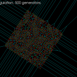
Some progress on the voronoi-diagram algorithm. It doesn't crash easily now with random or regular input points. Not crashing is good, but whether the output converges towards the correct diagram or not remains to be seen...


Voronoi diagram error
Playing around with the vd-code has highlighted some problems. Using double-precision floating point numbers for coordinates, strange things start to appear when the coordinates are around 1E-6 or so. It's not possible to accurately compute the sign of the in-circle predicate (a 4x4 determinant) and the diagram update should instead be based on topological reasoning.

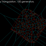
Delaunay Triangulation
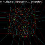
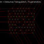
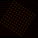
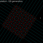
The dual of the Voronoi diagram is the Delaunay triangulation. Here I've modified my earlier VD code to also output the dual (shown in red). If this can be developed further to do constrained Delaunay triangulations (arbitrary pockets with islands) then it will be useful for cutter-location surfaces in opencamlib.
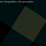
The regular grid is, in the words of the GTS website, "a much more difficult test than it looks".
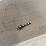
Lathe work
A 31mm long prototype part with 6mm diameter in one end and 3mm at the other. From an M12 stainless steel threaded rod (the only stainless at hand...)

3D printer - day 2
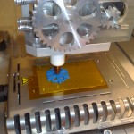
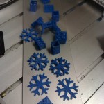
Some more 3d printing and testing today. The video shows a snowflake, thing:1321. G-code was created with repsnapper. We are using a Weller hot-plate meant for smd-soldering, covered with kapton tape, as the printing base.
Here's video from Risto's blog (shot with an N900, I like the quality):
3D printer – first test
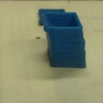
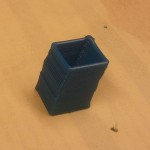
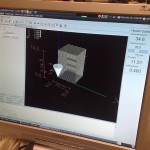
After some initial tuning we did three test-prints today of a 10x10mm square, 30 layers, raising the z-axis by 0.5mm for each layer. We tried to set it up so that when the X or Y-axis moves 10mm, the extruder A-axis should also move 10 units. The way it is set up right now it might be extruding slightly too much plastic per mm. The maximum feedrate we tried was 600mm/min.
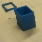
We printed the same geometry three times, here is the second try (in the first try the base/bed wasn't staying very fixed, so the print resembles the leaning tower of Pisa...)
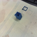
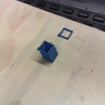
Here is the third try. Now we are moving the Z-axis +0.5 mm during the last Y-axis move. This is at 600mm/min.
We were pretty happy with the print-quality so far, considering this is the first ever test of our extruder/xyz-table setup. Some tuning of how much plastic is extruded for each mm of xyz-feed, and perhaps a heated printing-bed, should improve the quality further. Next is learning to use one of the many STL to G-code CAM programs and filtering the G-code output so it is suitable for our EMC2 setup (the extruder is the A-axis, in absolute mode).
Update: Risto has more on this in his blog: ?http://risto.kurppa.fi/blog/2010/12/first-prints-with-reprap-the-open-source-3d-printer/
Extruder test
The temp-control electronics, together with a stepper motor controller, have been packaged into a box, and I modified the EMC2 config to include an A-axis that controls the extruder stepper motor. The extruder seems to work, but the big cog-wheel that feeds the ABS plastic rod could be improved. It now slips a little too easily, especially when the corrugated area which pushes against the plastic rod fills up with small bits of plastic. Next up is mounting this on an XYZ-table and trying to 3D print something!
EMC2 halui jogging example

The slider is used to set the jog speed in units of mm/min and the buttons jog the axes in the + and - directions.
HAL and XML files: halui_jog_example