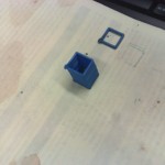
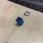
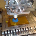
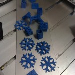
3D printer – first test


After some initial tuning we did three test-prints today of a 10x10mm square, 30 layers, raising the z-axis by 0.5mm for each layer. We tried to set it up so that when the X or Y-axis moves 10mm, the extruder A-axis should also move 10 units. The way it is set up right now it might be extruding slightly too much plastic per mm. The maximum feedrate we tried was 600mm/min.

We printed the same geometry three times, here is the second try (in the first try the base/bed wasn't staying very fixed, so the print resembles the leaning tower of Pisa...)

Here is the third try. Now we are moving the Z-axis +0.5 mm during the last Y-axis move. This is at 600mm/min.

We were pretty happy with the print-quality so far, considering this is the first ever test of our extruder/xyz-table setup. Some tuning of how much plastic is extruded for each mm of xyz-feed, and perhaps a heated printing-bed, should improve the quality further. Next is learning to use one of the many STL to G-code CAM programs and filtering the G-code output so it is suitable for our EMC2 setup (the extruder is the A-axis, in absolute mode).

Update: Risto has more on this in his blog: ?http://risto.kurppa.fi/blog/2010/12/first-prints-with-reprap-the-open-source-3d-printer/

Extruder test

The temp-control electronics, together with a stepper motor controller, have been packaged into a box, and I modified the EMC2 config to include an A-axis that controls the extruder stepper motor. The extruder seems to work, but the big cog-wheel that feeds the ABS plastic rod could be improved. It now slips a little too easily, especially when the corrugated area which pushes against the plastic rod fills up with small bits of plastic. Next up is mounting this on an XYZ-table and trying to 3D print something!

Temperature PID control

We hooked up the temperature measurement circuit and the PWM-amplifier to EMC today and tested PID-control of the extruder head temperature. The ini, hal, and xml files for this are here: temp_control_pid.tar

It's probably much easier to figure out the connections from the diagram below than to browse the text files. The square wave, which has a frequency proportional to the temperature, comes in on parallel port pin-13, and is connected to an encoder. The encoder has a velocity output which will be equal to the frequency of the square wave in Hz. This frequency is used as the feedback for a PID-component which compares the measured frequency against a set-point which is taken from a pyvcp slider. The pid output is used as an input to a pwm-generator, whose output needs an inverter, since the pwm-amplifier is active-low. The PWM is output on parallel port pin 9.

I wish there was a tool which would draw these HAL/pyVCP diagrams automagically from the source files. There is some work in that direction already: crapahalic and HAL with gschem.

Temperature control circuits

I made two small circuits today for temperature control of the extruder head on a reprap type 3D printer. The idea is to control the temperature, which needs to be somewhere between 200 and 240 C I think, using EMC2 and two parallel port pins.

The first circuit is based on the 555 and produces a square waveform with variable frequency depending on the resistance of a thermistor. At room temperature the thermistor resistance is 100 kOhms and the output frequency is below 1 Hz, and when the temperature is suitable for extrusion the thermistor resistance is about 200 Ohms which produces an output frequency of around 25-30 Hz. If the EMC2 base-thread runs with a 50 us period then it should be possible to record the frequency of this square wave using an input pin on the parallel port with an accuracy of roughly 1/500 (half a degree C?), which should suffice.

Testing the heating side of things, a wire with about 6 ohms of resistance wrapped around the extruding head, showed that a suitable DC voltage is around 8 V and produces a current of 1.3 A. The idea is to use a HAL PWM-generator to drive the base of a 337 transistor which drives the gate of an IRF610 FET that controls the current through the heating wire. By adjusting the PWM duty cycle it should be possible to control the temperature using a PID controller based on the temperature measurement.