Howland constant current source

For pushing a constant 500 uA current through Pt100 temperature sensors I am using a Howland constant current source.

howland_circuit

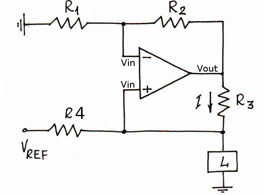
I'm using an OP2177 op-amp. The OPA2188 would have been better, but the delivery time was too long. The four resistors come in a single 4x10k array package, and are matched to within +/-0.05 % (ACASA1002E1002P100). The reference voltage comes either from an external source, or an on-board 5V ADR425.

We did a test of how good the current source is, and came up with this data:

howland_data

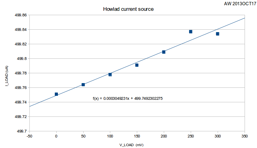
The slope corresponds to an output impedance of 3.6 MOhms. Note that when we change the load resistance from 0 Ohms to 600 Ohms the load current changes by 83 nA, or less than 0.02% of full-scale (500uA). The 6.5-digit multimeter in the electronics lab was mostly oblivious to this change, so we used a 3458A instead 🙂

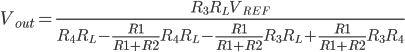
I then wanted to calculate what contribution the tolerance of the resistors R1-R4 make to the output impedance. Assuming an ideal op-amp (infinite gain, so V+ and V- at same voltage), the op-amp output voltage can be seen to be (left as an exercise for the reader):

Now we can make a monte-carlo simulation by picking values for R1-R4 with a nominal 10k resistance and an added +/-0.05% tolerance. I did this by adding a normal-distributed resistance with zero mean and 5 Ohm std-deviation.

1
2
3
4
5
6
7
R0 = 10e3
mu = 0
sigma = (0.05/100)*R0
R1 = R0 + random.gauss(mu, sigma)
R2 = R0 + random.gauss(mu, sigma)
R3 = R0 + random.gauss(mu, sigma)
R4 = R0 + random.gauss(mu, sigma)

I then repeated the output impedance calculation many times, and plotted this output impedance histogram:

howland_output_impedance

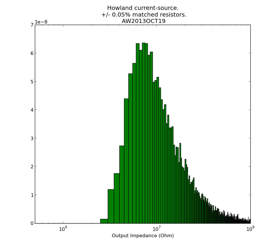
It seems our measured 3.6 MOhms is slightly low, and from the resistors alone something closer to 10 MOhm should be expected. Non-ideal behaviour of the op-amp, which I haven't considered here, may also contribute. Python-script for producing the histogram: howland_calc.py

See also: AN-1515 A Comprehensive Study of the Howland Current Pump (up to 1 MOhm output-impedance with 1% resistors is mentioned)

This current-source is part of the Pt100 frontend.

Ubuntu 13.10 notes

Reinstalling Ubuntu on my laptop, a Lenovo IdeaPad Yoga 13".

Creating a bootable USB stick:

  • On another Ubuntu machine, use "Disks" from the menu to remove old partition, create a new one, and format a 1 GB stick
  • Use unetbootin to write the latest ISO from http://www.ubuntu.com/download to the stick

For some reason the driver support for this laptop is not that great. Wifi, bluetooth, screen brightness control do not work with standard Ubuntu. Amazingly the touch-screen does work - but I don't use it much. The wifi driver is an absolute must, since the machine does not have an Ethernet port.

Wifi driver fix:

git clone https://github.com/lwfinger/rtl8723au.git
cd rtl8723au/
make
sudo make install
sudo modprobe 8723au

Screen brightness fix:

  • Add the acpi_backlight=vendor to your grub default command line in /etc/default/grub, i.e. GRUB_CMDLINE_LINUX_DEFAULT="quiet splash acpi_backlight=vendor"
  • sudo update-grub
  • blacklist the ideapad_laptop by adding "blacklist ideapad_laptop" to your /etc/modprobe.d/blacklist.conf file.
  • sudo reboot

Useful packages and random tweaks:

  • git
  • build-essential
  • synaptic
  • indicator-multiload
  • flashplugin-installer
  • Firefox plugins: Tab Mix Plus (Why isn't multi-row tabs standard on Firefox?? I NEED about 8 rows of tabs!)
  • geany (simple text editor)
  • Privacy: from the menu "Privacy" then on the second tab turn OFF "record file and application usage"
  • filelight (see where all the diskspace went!)
  • vlc
  • stellarium (star map)

External sources

NTP to keep the system clock on time

  • sudo apt-get install ntp
  • add time1.mikes.fi and time2.mikes.fi to list of servers to /etc/ntp.conf
  • sudo service ntp restart
  • check that it is working: watch -n 2 ntpq -np

Reasons to still have a Virtualbox Win-7 install:

  • PADS schematic and PCB design - but I am trying to learn Kicad now
  • Wireless USB-stick based transfer of GPS data from my Garmin devices (I think this is doable in linux, I just haven't had the time to learn)
  • QuickRoute for plotting orienteering maps/GPS-data (I'ts a .NET application, so maybe would run under mono?)
  • Mechanical CAD applications. FreeCAD is on the way to become usable for serious stuff - but not yet...
  • NI Multisim for SPICE simulations. Is there a good alternative for linux?

Lost inside the control-circle

2013-10-02-kuusijarvi-qr-splits

Night-orienteering yesterday at Kuusijärvi. I managed to be "lost inside the control circle" on four of the ten controls. Being so close to the control and not finding it usually never happens in daylight - but darkness changes everything 🙂

control_circle_1
#1: the plan is to use path (A), but I find (B) instead and that works too. North towards the blue swamp with two stones (C), turn right and up onto the grey cliff/hill, and the control should be there. Well no, down the wrong direction of the hill and stop at D. It has to be this hill anyway so I turn back and see some other runners who come out of the control.

control_circle_2
#2: On the way to the control hills (A) and (B) are more or less easily recognizable. Then I failed to notice the path between (B) and (C), and didn't see the large stone (C). Aimless circling around until I find the surprisingly large stone (D) (why wasn't it drawn larger?) and ca re-locate roughly on the map.

control_circle_5

#5: on compass bearing up the hill A, and then down the steep slope B. Yes! I see the smaller bump C and the control is right behind that one. Eh, well no, maybe it's more north. Meet some other runners at D, turn around, and find the control.

control_circle_9
#9: Clearly a difficult control with lots of detail on the map. So a careful start from the very clear corner in the big path A. The plan is to go straight south to the control but the network of paths causes drift to B before my direction turns properly south. Onward south then, but no control in sight and I finally relocate at the highest point on the hill with a steep cliff C. From there finding the control is straightforward.

Iltarastit, Solvalla

2013-09-29-solvalla

#12 OK
#25 should have run straight north into the control circle from the cliff, instead veered right and circled round
#18 felt OKish but the descent down the steep cliff was apparently slow and the split isn't great.
#8-#26 OK
#27 straight over the swamp would probably have been faster
#10 drifted into the swamp close to #29, maybe +1 min there. After I saw #29 I ran too much north and going down the hill didn't know at which cliff I was. Found #10 mostly because of other runners.. Worst split.
#23-#22-#11-F Some orienteering to reach the road before #23 but then just mainly running strength required. Not much lost on the three last legs 🙂

Itärastit, Landbo

2013-09-28_itr_landbo

#1-#2 OK at easy speed
#3 small hook inside the control circle
#4 best split and direct route, but very slow going up the steep hill
#5-#6-#7 OK
#8 gave advice to someone just before the control, then ran past control myself until I stopped at two big rocks. worst split.
#9 from the bigger road I missed the path I wanted to take (blue line), and had to find it through the woods instead.
#10-#11-#12-#13-#14 more runners both in front and behind on these controls. Nothing special to report on.

NTP shared-memory refclock driver for White Rabbit SPEC

ntp_graph

I've been playing with White Rabbit hardware at work. White Rabbit uses a combination of SyncE and PTP to perform very precise (<1 ns) time-distribution.

The standard low-precision way to distribute time is NTP. I hacked together a very experimental "Type 28" NTP refclock driver that reads the WR-time from SPEC shared memory and writes it to another location in shared memory where NTP expects it. Code over here: https://github.com/aewallin/ptp2ntpd

The graph shows system clock variations compared to WR-time (which we assume is very accurate) for a computer with the WR-refclock driver enabled (blue trace, minpoll 16 s), and another computer where the system clock is kept on time using standard NTP (I just added some servers to ntpd.conf, no other settings changed from default Ubuntu 12.04LTS). The WR-disciplined clock stays within maybe 50 microseconds with no net drift during the ~9 hour measurement, but the trace is quite jumpy. The NTP-disciplined clock wanders around much more (300 us) but the trace is smoother.

Agilent 34901A and 34907A breakout boards

Update 2015-09-16:  Csaba Toth sent a picture of his front-panel for these breakout boards. Very nice finish with text/graphics on the 19" rack panel!

20150908_231719

Front

Update 2015-05-15: Files for PCB manufacturing: top, bottom, outline Gerber files, and Excellon drill files.

When opened with e.g. gerberview they should look like this:

breakout2 breakoutThe connector placement is shown here (sorry I don't have a drawing for the one with 20 BNC connectors):

breakout2_connectors

A frustratingly large portion of any electronics or control system build has to do with cables and connectors. So here we go...

I'm using an Agilent 34970A datalogger/switch, which is a 6.5 digit (~22 bit) multimeter that takes up to three plug-in modules with various functions.
I'm using one 34901A module for 20 channels of DC voltage inputs. On the module there are 40 screw-terminals for these voltages which I have connected to a 40-pin ribbon cable that connects to this breakout board with 20 BNC connectors. Our PCB-mill can do 300mm long PCBs, which is just long enough for this board if the BNC connectors are interleaved on different sides of the board. Mounting BNC-connectors right next to each other on the same side is bad idea anyway as the connectors on the cables will not fit that closely. It should be possible to mount the whole thing in a 1U 19" rack panel.

34901A_breakout_top_2013sep 34901A_breakout_bottom_2013sep

For controlling the TEC drive I need analog outputs, provided by a 34907A module. Again I'm using a 40-pin ribbon cable from the screw-terminals on the module, and the breakout board has four BNC connectors: Two DAC outputs, one counter input, and a gate input for the counter). Additionally there are two 8-bit digital I/O ports which are routed to two DB9 connectors on the breakout board.

34907A_breakout_top_2013sep