A test of the 8-channel 0-7 kPa microfluidic pressure controller today. We're looking through a 100x inverted microscope. There's a 2 um latex bead in a ~40 um wide channel formed between a glass coverslip and a PDMS layer. I'm hitting the keyboard to either increase or decrease the pressure in steps of +/-35 Pa which allows me to just barely keep the bead within the field of view during the 1 min video. The controller has plenty more resolution, down to about 1-2 Pa, so it should be possible to control flows down to <1 um/s. Stay tuned for more of the same later...
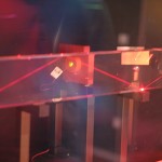
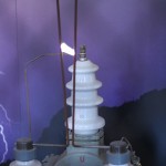
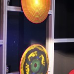
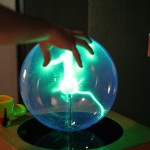
Supercontinuum

Saw some supercontinuum (a better explanation here) generation in the lab today. At the top there's a diode laser at 808 nm (the bright white light in the pic, try photographing your TV-remote with a digicam!) that pumps a YAG laser which outputs a 1064 nm pulse. This is then converted to a 532 nm pulse through second harmonic generation and directed into a very fancy holey-fiber in which the supercontinuum is created. In the middle of the pic there are two reflections from a diffraction grating. To the right the zero order diffraction which looks like mostly 532nm to the camera/eye, and to the left the 1st order diffraction where you see a fair bit of blue to the right of the 532nm peak and a bit of yellow/red(ish) to the left of the peak.
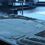
Microfluidics test

I got some new microfluidic chips to play with today (courtesy of the Microfabrication Group at TKK). This must be cutting-edge research, since there's an article about using laminar flow cells for single molecule experiments in the latest issue of Nature Methods. I'm testing our custom-built pressure controller which controls the inlet and outlet pressures between 0 and 7 kPa with about 2 Pa resolution. There are three inlet channels (~40 um wide) with blue fluid in the top channel, clear fluid in the middle, and red fluid in the bottom channel. They all meet in the middle of the chip and there's a wider (120 um) outlet channel.
The pressure controller is similar to Fluigent's (described by Fütterer et al. in Lab on Chip), and I'm gluing the 0.6 mm PTFE tubing to the PDMS chip as described by Hartmann et al. in Lab on Chip.
The video shows a sinusoidally modulated pressure applied to each of the input channels as well as varying the pressures manually between zero and maximum.
Rigid Tapping
We've mounted a 500 cpr encoder on the spindle-motor which means it's possible to do rigid tapping. Above some spot-drilling, then a 2.5 mm drill, and then an M3 tap at 500 RPM and 0.5 mm Z-feed per revolution. Below the same thing but with a 5 mm drill and an M6 tap (1 mm Z-feed per rev).
Cool stuff!
Aluminium milling video
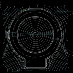
As promised, the video of the roughing + finish operation on the finderscope-ring drilling jig.
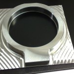
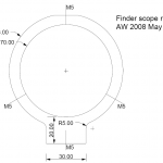
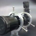
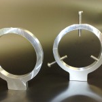
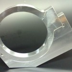
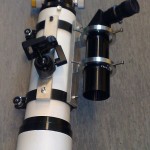
Finderscope rings

Last weekend we made some rings for mounting a finderscope on the main telescope. Today I got the holes drilled and tapped so the rings are ready to use. The gallery below shows the adaptive pocketing paths that were used to cut both the part and the jig that allowed drilling the holes at +/- 120 degrees.
There is a video of the roughing operation at 2000 mm/min that will be online soon.
Bulb Milling Videos
Jari shot some videos during the milling of the beaver-tail bulb. They now appear on YouTube.
For a mostly home-built cnc minimill of this size, this is pretty 'hard core' stuff...
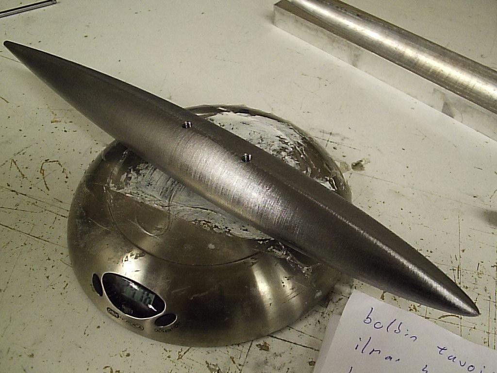
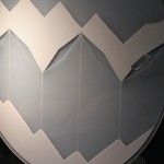
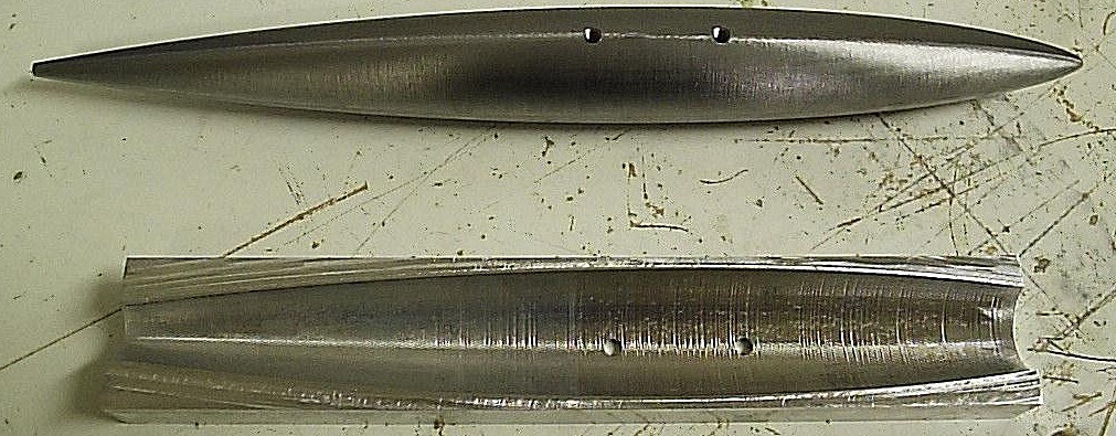
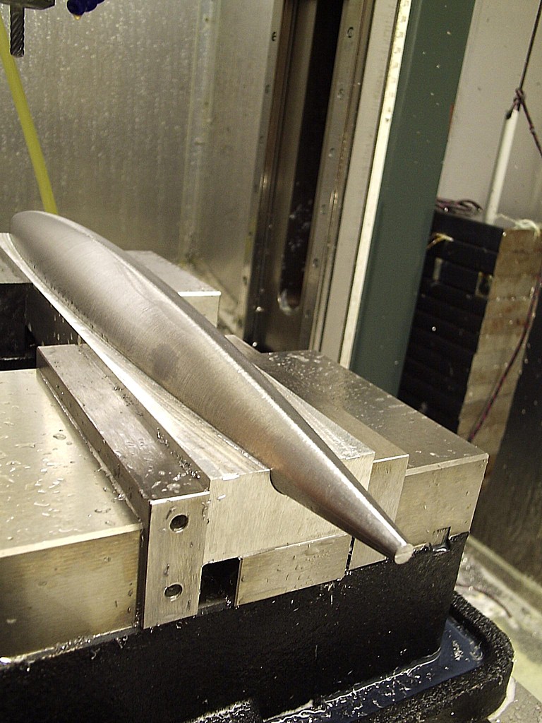
Steel bulb nr3
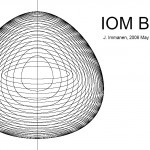
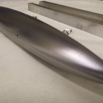
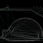
Jari made this steel bulb over the weekend. It has a slightly triangular cross section in the beginning which flattens out to a 'beaver-tail' at the end.
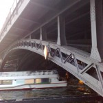
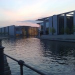
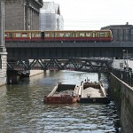
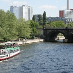
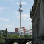
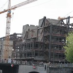
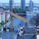
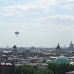
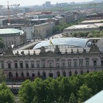
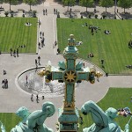
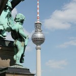
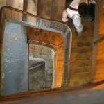
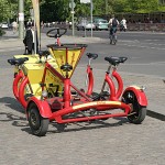
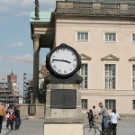
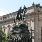
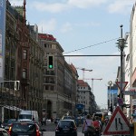
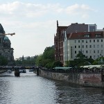
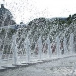
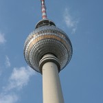
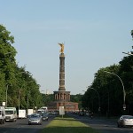
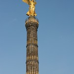
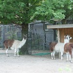
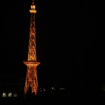
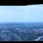
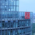
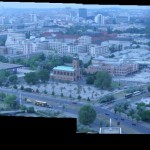
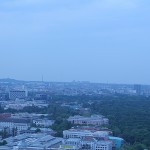
Three days in Berlin
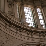
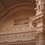
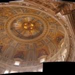
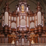
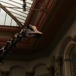
JPK Instruments hosted a one-day Optical Tweezers meeting in Berlin on Thursday. We heard 9 talks and looked at about 30 posters, one of which was mine. As I had not been to Berlin before I reserved a day and a half for looking at the city and its attractions.
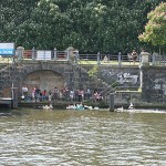
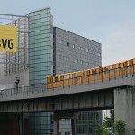
Public transport works very well in Berlin. With one ticket you get to ride the S-Bahn (trains), the U-Bahn (underground), and Strassenbahn (trams). They're all on time, fairly fast, and not too crowded. In addition you get to see the nice train stations, some from 1880 or so.
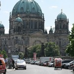
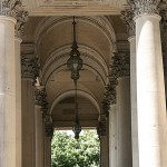
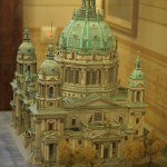
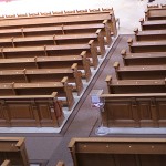
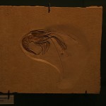
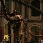
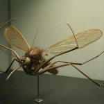
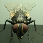
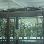
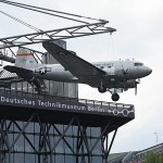
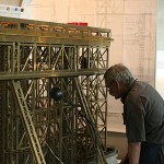
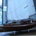
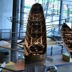
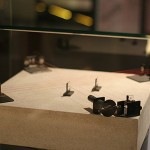
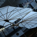
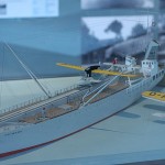
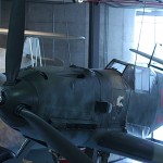
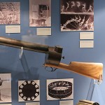
The pictures are from Berliner Dom (note numbered seats. Ordnung muss sein!), the Museum fur Naturkunde (see all those species you never knew existed), and the Deutches Technikmuseum Berlin and Spectrum (the latter was more fun with all kinds of hands-on experiments).
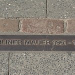
The Mauermuseum at Checkpoint Charlie was interesting, but presented so much pictures, text, and newspaper clips that it was hard to stay focused towards the end.


This is the first time I'm using the WordPress gallery feature. It seems to work although right now the ordering of the pictures is a mystery to me. How do you like it?
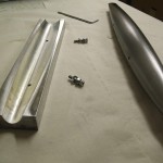
Steel Bulb nr2
After the test run on Saturday Jari made a complete bulb in steel on Sunday. The first half can be milled with the stock clamped to the vises, but for the second half we need this jig. It's in aluminium and was fairly simple to make - which also means making a bulb mould in aluminium should be easy. If someone is interested in a bulb mould, do drop me an email.
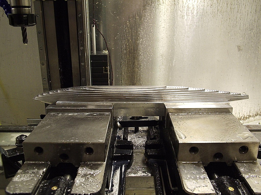
Milling the second half proceeds exactly like the first half. Here the rough-program is run leaving about 1 mm minimum of material for the finish pass. We now adjusted the program for a bit faster feedrate and much faster plunge-rates as it is clear the program is error free and all plunges are outside the stock.
Surface finish is slightly better than on the trial bulb. The design weight was 2410 g and this one came out at 2416 g - pretty good. With a 100-150 g fin trimming the total weight close to 2500 g shouldn't be a problem.