I've been hacking away at openvoronoi, adding support for polylines and polygons.
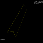
The code I had in November works with individual non-intersecting line segments, like this:

Note how each vertex in the figure above is of degree three, i.e. there are three edges incident on each vertex. There's something about the number three, or triangles, or both, that makes planar graphs of degree three particularly nice to work with.
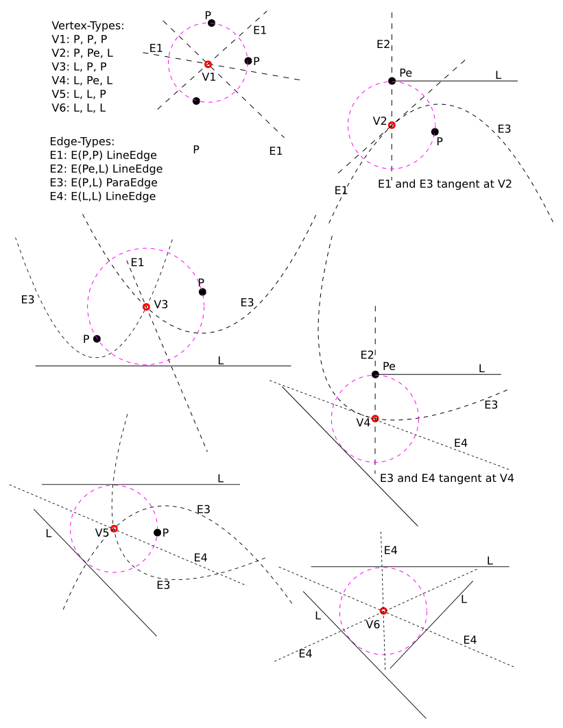
Here's the same figure with some notes describing the elements. The line-sites are drawn in yellow, and are associated with their left R(L+) and right R(L-) regions. The purple lines are called separators, and they define the region associated with the start- or end-point of a line-site. The three possible edge-types are also shown: LineEdge between two point-sites, LineEdge between two line-sites, and a Parabolic (PointLine) edge between a point-site and a line-site.

Now, things get more complicated when we want to 'glue' two line-segments end-to-end in a polyline, or glue three or more line-segments together to form a polygon. Vertices are not necessarily of degree three any more. In fact the vertex degree is essentially unbounded, as you can start/end arbitrarily many line-segments at the same vertex. The solution I am using is to introduce what I call a null-face with zero-length null-edges around each point-site to which more than one line-segment connects. The mental picture is much like that of a key-chain, or mountaineering carabiners that are hooked-in to a loop. When we want to use the a vertex as a start/end-point for a segment we 'hook-in' to the null-face:

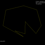
This introduces a number of new rules and associated code for how vertices should be created, removed, and moved around a null-face, but it seems to work somehow now:

Note how these null-faces and the circular null-edges around each end-point result in degree three vertices, which are much nicer to deal with in the algorithm. For example, the null-face around vertex "0" is 40->85->86->41->39. Without the null-face construction this vertex would be of degree five. Here is an annotated version of the same picture:

This image shows how the diagram divides the plane into regions associated with endpoints such as R(0) and with the right/left side of a line-segment such as R(0-29) and R(29-0). The null-edges that form null-faces around each end-point are drawn in white.
Of course, these null-edges are only a topological construction. Geometrically we can position each vertex on a null-face at the location of the encircled point-site. This effectively contracts away the zero-area null-faces, and the result is the diagram we want:

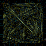
The code now runs for a few select test-cases. To be continued...
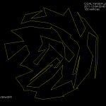
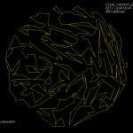
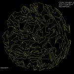
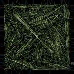
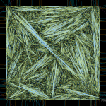
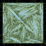
Update: The code now seems to work also for random polygons with a large number of vertices. Here is one with 400 vertices:

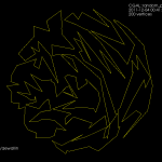
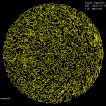
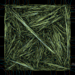
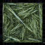
and 3200-vertices:


