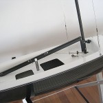
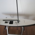
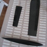
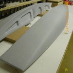
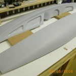
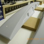
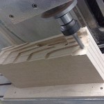
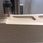
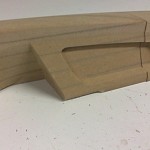
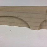
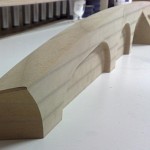
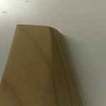
Archive for the ‘IOM Building’ Category

Noux building in Norway

Monday, March 26th, 2007


Steinar from Norway sent me some more pictures of his Noux boats. He has completed the first boat (see below), and is now building a second one.


Another view of the spray-painting setup.


The bulb is home-made, cast in a plaster mould.


Here is Steinar’s first boat, now completed and painted. I posted some building pictures earlier here and here.

Steinar asked if there is a Noux-logo. Sure! I just need to post it online in some common format. Stand by…

Compression strut for Gooseneck

Sunday, February 11th, 2007

Two new parts for the gooseneck: a compression strut from Sails ETC, and a DIY mast-ram.

The compression strut fits the lower end of the gooseneck (bottom left), and if you bend it a little bit, it will fit a Sails ETC eyebolt too (far right) - which I plan to use on the boom. The mast-ram consists of a plastic fitting (Maritim) that grabs the mast, a stainless steel M4 bolt (I need to open the plastic fitting a little so the head of the bolt sinks into the plastic). A brass M4 thumbwheel (Ruuvikulma) provides adjustment.

Noux pics

Thursday, January 18th, 2007

Steinar from Norway who started building a Noux in December now sent me some pictures of the finished boat.

Gooseneck prototype

Tuesday, January 2nd, 2007

We’ve been designing a ball-raced gooseneck for the new Noux boats. Jari sent me some pictures of his progress.


These pieces are mounted around the mast. There are two sizes, for either 12.4 mm or 11 mm Easton masts. The smaller hole is 6 mm in diameter and fits a flanged miniature ball bearing.

This piece goes on the bottom of the gooseneck axis. It has a raised ring towards the bearing, so that it makes contact only with the rotating part of the bearing.

Here’s the first assembled prototype, with bearings fitted to the parts shown in the top picture. A 6 mm diameter aluminium rod forms the axis of the gooseneck. The rod is drilled and tapped with M3 threads in both ends. At the top, a Sails ETC flat eyebolt screws into the axis. At the bottom, the part shown above is secured with an M3 screw. We’re hoping that the eyebolt at the top will fit the standard Sails ETC mainboom front end fitting.

We’ve not come to a final decision on a variable-length compression strut or kicking strap yet… The standard Sails ETC fitting works, but it attaches to a hole in the boom, which over time tends to corrode and wear into an oval shape. Bright ideas required ;)

Building IOMs around the world

Friday, December 15th, 2006

People from all over the world keep sending me pictures of their Noux or other IOM projects - many thanks ! Here are a few recent ones:

Matt from Australia sent me these two pictures of his planking process:

The next two pictures are by Boris from Switzerland who started planking in November and has now completed the hull:

Finally, Steinar from norway has made rudder and fin moulds for his Noux. These are made the old-fashioned way by hand, no cnc-machining…

That’s it for now… stay tuned for some cnc electronics updates which I hope will happen soon, and we’re also planning a ball-bearing gooseneck fitting for the Noux Mk2 which might be prototyped before next year.

Norwegian Noux News

Monday, December 4th, 2006

Steinar from Norway wrote to tell me about his Noux project. He started out building a planked wooden Noux (above), but it ended up too heavy, so instead a wooden plug was made (below)

Using this plug Steinar has now made a mould and moulded a few glassfiber Noux hulls. There’s no standard deck solution for the Noux yet so Steinar has invented his own, with a central round hatch for access to the electronics.

A Swiss Noux

Friday, November 10th, 2006

Boris from Switzerland sent me these two pictures of his Noux project which he has just started - thanks !

CNC machined tiller arms

Monday, November 6th, 2006

Jari sent me some pictures of tiller arms that he machined during the weekend.

These parts need to be machined in three separate stages, here’s stage 1 where the tillers are first roughed and then finish milled.

Here’s what the parts look like after the first stage. After finishing the hole for the axle and three holes for the push-rod are drilled. In stage two the parts are turned 90 degrees and fixed using a jig. A hole can then be drilled and tapped for a set-screw that will tighten against the rudder axle.

In stage three the whole thing is flipped over and the bottom of the stock material is machined off, which results in these completed parts.

These are still prototypes, for the Noux Mk2 I’d like to see two things: (1) assembly of the boat without tools, i.e. the attachment of the tiller arm to the rudder axle should not require any special tools (allen key, screw driver, etc.). This could be achieved with the current design simply by using a screw with a thumwheel. (2) a fixed relative position between tiller and rudder axle, i.e. when I attach the rudder I want to be sure it sits straight without having to check it everytime and possibly re-trim on the transmitter. A low-tech solution is to file or grind a flat part on the rudder axle onto which the set-screw pushes. If anyone has better ideas I’d be glad to hear about them !

Update 2006 Dec 05:

Johan Prak from the Netherlands sent me a picture of his homemade rudder fitting. A very simple design that anyone can make:

Noux Radio Installation

Sunday, November 5th, 2006

This is the shape and placement I finally settled on. Above is the mould, cnc milled from two 15mm thick pieces of aluminium bolted together. Very similarly to Craig Smiths Obsession I am going to mount the RMG winch on one side, and have a compartment for the battery on the other side. This is not the conventional way to do vacuum moulding, here I’m using only a bag, normally the laminate is followed by a release film, and the a breather (white fabric above), but I find all of this too complicated for small parts. Using just the bag works almost as well, an improvement is to use more of the breather around the laminate so the pressure spreads a bit more evenly. Vacuum bagging need not be high tech: the bag is a plastic bag used for selling fruit in a supremarket, and our pump is an old refridgerator compressor I got second-hand from a repair shop for about 5 eur…

Here’s the finished part. Surprisingly stiff with three layers of 165g twill weave glassfiber - it must be all the shapes and angles that does it. Moulded with a vacuum bag (above) to ensure that the fibers follow all the 90-degree bends a bit better. In the picture the bottom of the battery compartment is still in place - the bottom will obviosly have to come off and I will fit some other support for the battery which is about 50mm deep. I didn’t want to mould something that was a 50mm deep hole in one go, this part is hard enough to release from the mould as it is.

This is what the RC-tray looks like when mounted in the boat. Here we have first the pot-recess which is moulded into the aft-deck. Into that recess the rim of the rc-pot is pressed, and the rc-tray laminate fits into the pot-rim. I’ve indicated using colors and text approximately how the components are going to be installed. The tray will be fixed to the rim and deck using three M3 screws, which will thread into rivet-nuts that are epoxied to the aft-deck. The rudder servo will require its own mounting bracket - that’s next on the design/build to-do list.

Noux RC-Pot Recess Progress

Friday, October 13th, 2006

We’ve moulded the first aft-deck with the new pot-recess for the round lid+rim that is going to be the only hatch into the new boat.

(more…)