E-stop circuit

This is the E-stop circuit I am going to use when upgrading the cnc-mill to servo control. The idea is to use a wire-OR circuit (series connection of NC switches) for things that cause an E-stop followed by a wire-AND circuit (parallel connection of relays) for things I want to happen at E-stop.

The E-stop out signal from EMC is wired to the top right of this board (labeled E-stop IN...). When this signal goes high it closes the rightmost relay which has +12V wired to it. The 12 V then goes through a series of NC switches, which I've here just shorted out with the black wires. In reality the black wires will be replaced by one E-stop button on the main enclosure, one E-stop button on the jog-pendant, X/Y/Z limit switches, NC servo-amp fault relays, and a VFD NC fault relay.

When all is well +12 V is supplied to the three other relays, and these provide NC or NO outputs. One is used to tell EMC everything is OK (E-stop IN signal in EMC), one is used to enable the power switch of the axis servos, and one is spare for now.

This should make the machine reasonably safe. If any of the E-stop buttons are pressed, a limit is tripped, or the servo amps/VFD are not feeling well we should go into E-stop, and that will cut power from the servos. EMC will also notice this and I'm relying on EMC to shut down the coolant pump and the VFD.

Spektrum DX6 antenna mod.

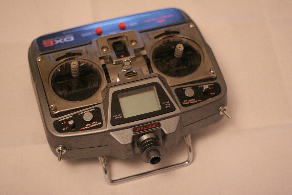
By popular demand, some notes on how I've placed the antenna of my Spektrum DX6 transmitter inside the case. I've been using the radio like this ever since I got it and provided that you hold up the radio more or less vertically and not hide behind large metal constructions or things like that the range is fine. The benefit of the internal antenna is that I don't have to worry about breaking it while sailing it or storing the protruding thing in the toolbox. When it rains it's nice to fit the whole transmitter into the rain-cover which doesn't have any (potentially leaking) holes (other than the two holes for my hands!). A plug for the antenna hole to prevent dirt etc. entering the Tx would probably be a good idea.

If someone has a feeling for what theoretically a 2-3 mm wall of plastic does to an RF signal at 2.4 GHz, let me know.

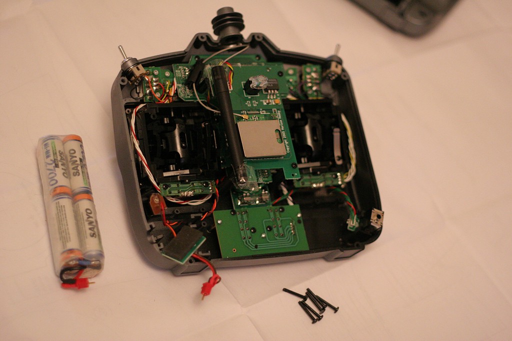
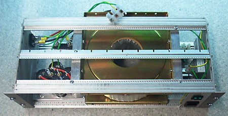
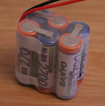
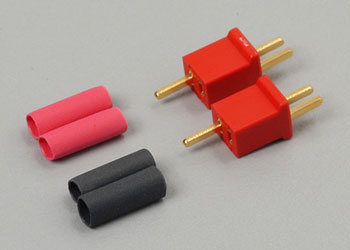
Here is the back cover and six screws that hold it removed along with the battery (I've put Deans connectors on the Tx battery to simplify charging). With a stock DX6 the antenna would be sticking out at the top and there would be a few extra pieces of black plastic supporting it. I remember I broke some of those black plastic parts when I disassembled the antenna - so proceed carefully if you think you want to go back to the stock configuration sometime. I didn't touch the electrical connection of the antenna at all, the thin grey coax that comes out of the antenna attaches to the RF PCB just like it does on the stock Tx.

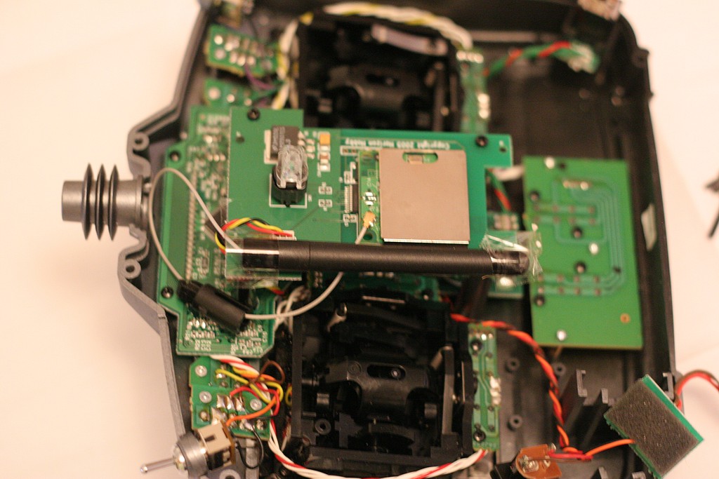
Here's a close-up of the antenna. You can see a part of the old antenna-hinge around the grey coax to the left (a bit dangerous to cut it away with a knife or pliers since you risk damage to the delicate coax). I've taped the antenna upside down to the RF board. There are probably other places inside the case the antenna could fit as well, but this seems to work OK.

If anyone has done something similar do let me know! I'd be happy to post pictures here if you send them to me.

Spektrum: I hope you are taking notes, I expect your next radio to have an internal antenna!

Talking about DX6 modifications, I did order the voltage regulator for the improved runtime modification, but the runtime with 2700 mAh NiMH's is just fine so I haven't installed the improved regulator yet.

Update 2007Nov17:

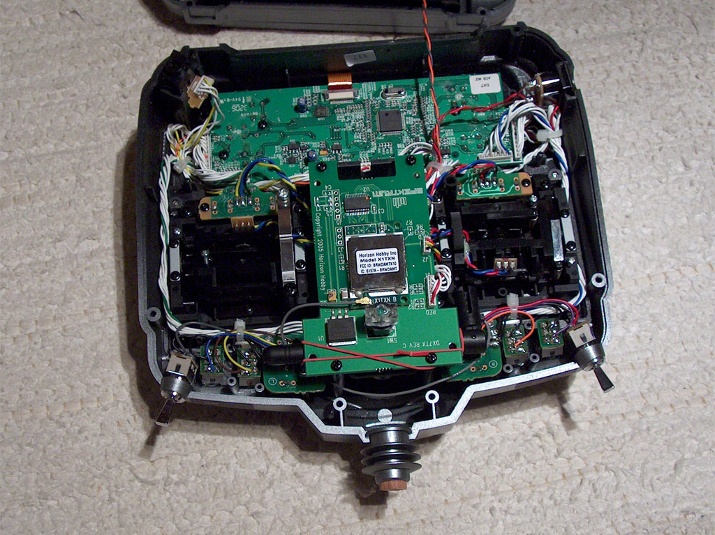
Olle Martonen sent me this pic of his modified Spektrum DX7. He mounted the antenna horizontally behind the regulator/switch PCB. Also note the wooden plug in the antenna hole. Not much sailing done with this system yet, but range-checking on the ground indicates there should be no problems.

I also got some observations be email on RF issues from a mobile-phone perspective: A few mm of plastic will not attenuate the signal measurably. Conducting materials are worse, like some mobile phone shells that are covered with carbon-containing paint, or your fingers on the back side of the transmitter. My placement of the antenna close to the RF-box (the metal square), and the PCB (also metal-coated), is not optimal, and could lead to an attenuation of 3-5 dB. A distance of 2-3 cm to the conductive parts would be better, so I'll maybe look for other places inside the Tx where the antenna could fit (Olle's example above is a bit better since the antenna is farther away from the RF-box).

Update 2007Nov22:

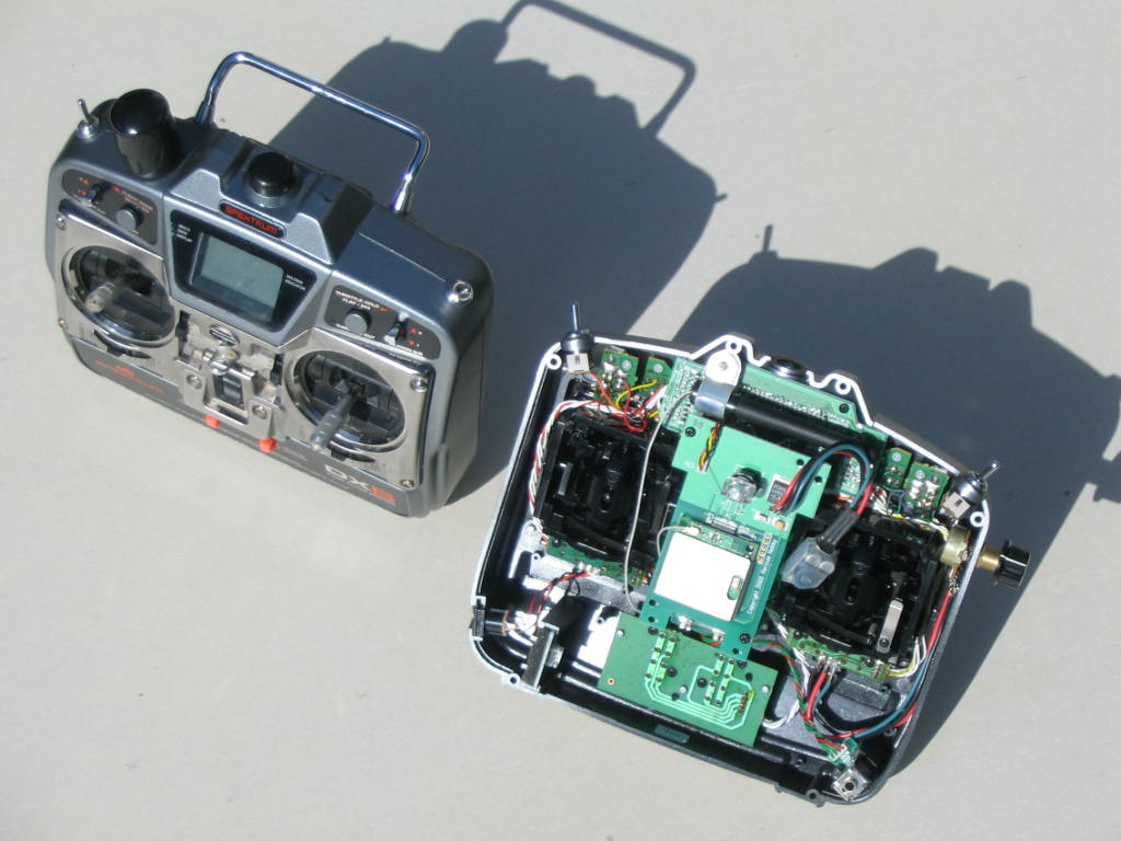
Winston Mathews sent me this picture along with a description: "Here are our modified DX6 radios. 2200 mAh batteries, new voltage regulator, jib-trim potentiometer and now "internal" antennae (mounted horizontally). Range is unaffected. Thanks for the idea and your help. I would advise to install the voltage regulator. We can sail for two days without recharging. " Photo by Jack Wubble, owner of the open radio in the pic. Discussion on this is over at the EC12 discussion forum.

Update 2007 Nov 23:

Some text and images on modifying a Futaba 2.4 GHz radio on the EC12 website.

Sepktrum DX6i, HiTec HSR-5990

Spektrum recently introduced an updated version of the DX6: the DX6i. Horizon Hobby also has an article on the new radio.

This one uses 'DSM2' technology which is described as giving 'full range'. Not sure what that means, but range should be better than with the first generation of 2.4 GHz radios, which at times was problematic (if you did something specific that cut down on the range).

I think the original DX6 was more or less a carbon copy of an existing JR transmitter, but the DX6i seems to be a new ergonomic design. Instead of buttons for navigating the menu it has a roller-device, and there's a new bigger LCD for programming.

The antenna still sticks out at the top even though nobody has had a mobile phone with an external antenna in years. I've mounted the antenna on my own DX6 inside the plastic case and it seems to work fine. I predict and hope that the next version in 1-2 years from spektrum will have the antenna mounted inside the Tx (no fear of breaking it, no problems with leaking rain-covers).

It's going to be in stores in December, for around $180 without servos, which is similar to what the 6-channel 2.4 GHz Futaba sells for.

HiTec has replaced their previous robot servo (HSR-5995, now discontinued) with a new version called HSR-5990. The specifications are roughly the same as for the old model: torque is 24.0 or 30.0 kg.cm depending on if you use a 6 V or 7.4 V battery, but speed is down a bit from 0.15s/60deg to 0.17s/60deg (6 V). The gears are Titanium alloy, and as is visible from the picture the new servo adds a heat-sink to the casing.

Maybe this is the winch for my next boat? At a cost around $110, weight of 68 grams, and 'ludicrous speed', it looks like a strong alternative to a drum-winch. Anyone have good or bad experiences with the 5995 or the new 5990?

More Pixels Please!

I reluctantly sold a 20" 1600x1200 Viewsonic with the desktop machine when I switched to my current T60 laptop (14" 1400x1050) about a year ago. The screen is not the strongest point of the T60, and that feeling has just been reinforced by looking at some 22" Samsungs at work. Now prices have plummeted again so I convinced myself that I need a 24" 1920x1200 Samsung 245B!

I need a smart way of managing my desktop for normal mobile use (1400 pixels wide), working at home with this new toy (1920 wide), and giving talks/lecturing with video-projectors that are usually only 1024 wide. Any ideas?

Transformer test

There was something strange going on when I measured the transformer last time, and since that I've gotten a few pointers from visitors to the blog and the CAD_CAM_EDM_DRO list.

I now did a test without the inrush current-limiter, and it does make a difference. It is rated for 8 A continuous current, but apparently it limits current much before that...

Now the 'AC load' line is measured by hooking up resistive loads to the secondary windings (no rectifier or caps), and it shows a series resistance of about 0.3 Ohms, or similar to what can be measured with a multimeter over the secondary windings. So at least the transformer seems to be working.

Then I hook up the secondary to the diode bridge and the caps and connect the same set of resistive loads as before. That's the 'DC load' measurements above. There again I see a big drop in voltage at first that then levels off somewhat. For the points above 5 A current the voltage drop is around 2 V per amp, or about a 2 Ohm effective series resistance. Also, the transformer does not emit any sound at all during the AC test, but now with the rectifier and caps when I load it up there is a slight 'humm' sound(probably 50 Hz and its harmonics).

I wonder if that 2 Ohm is typical or if there still is something strange going on? (could the rectifier bridge be too small? Anything wrong with my 4x 10 000 uF 100 V electrolytic caps?)

I tested this with one bridge rectifier GBPC5004 rated at 400V/50A and another one, a GBPC5010 rated 1000V/50A, but the results are the same. Looking with an oscilloscope at 6 A load at the DC voltage there is about 1.4 V of ripple.

1800 W 80 V PSU for servos

I've put together a simple unregulated power-supply for use with the DC servos that are going on the cnc-mill in the near future. The design is as simple as it gets: 230 VAC input, fuse, 2-pole switch, inrush-current limiter, 1.8 kVA toroidal transformer with twin 30 V secondaries in series, diode bridge, and finally four 10 000 uF electrolytes.

I did a load-test by hooking up various random devices I could find. It didn't exactly go as planned, since most stuff I could find is designed for 230 VAC. I had a resistor rated at 2000 W, a 500 W halogen lamp, a small oven etc. so you would think I could have gotten up to full load? But no, the stuff rated at 230 VAC doesn't dissipate nearly as much energy at 70 VDC 🙁

I was surprised at the largish voltage drop measured, but it's totally unregulated so something like this was to be expected. At about 7 A load I measured a voltage ripple of 1.4 V - which seems OK. A fit to the latter points show an effective series resistance of about 1.9 Ohms for the transformer. I've extrapolated my measurements with dashed lines up to around 1000 W which I estimate is the maximum we will ever use. Hopefully the voltage drop will not be problematic, since overall the system is under closed-loop control.

A new, faster RMG

Rob Guyatt, designer and builder of RMG winches has answered to the challenge from the super-quick arm-winch camp by sourcing a new motor for the RMG280D (the most popular model for an IOM). The motor is about 15% faster than the previous model, while torque is about the same or slightly less.

Couple the new faster winch with a bigger diameter drum, which trades torque (force on the sheeting line) for speed, and Rob has been measuring sheeting times, using a typical 310mm travel, which are very similar to what is achieved with an arm-winch. Above the RMG 280D with standard 26 mm drum in the middle, 32mm drum on the left, and 42mm drum on the right.

Here's the latest from Rob's drawing board (well, CAD program...). A spring loaded drum ! If I understand correctly one spool of the drum is fixed (and could be a spiral spool), and the sheeting line is connected to this spool. The other spool is spring loaded and will take out any slack in the return line of an 'endless loop' type sheeting system. Especially useful if the sheeting spool is of the spiral type, since the amount of sheeting line travel per revolution is then variable, and the spring loaded spool absorbs this variability.

Here the new RMG is sitting in the Noux RC-tray. There's just about room for the largest 42mm drum (flange outer diameter is about 50 mm). There's a thumb-screw on the drum, but it's a bit too high - the lid won't go on like this, so perhaps I'll grind down the thumb screw to about half its height. I've also taped on some supports for the battery, and a 6-cell AA battery fits comfortably. The idea for the rudder servo is that it will hang in an L-shaped bracket from the vertical wall of the RC-tray, final design and wether it will be stiff enough is still to be confirmed.

Update 2007Feb14: Rob has now finalized the design of the spring-loaded drum design and is offering it for sale at www.rmgsw.com 

X-peak 3 plus

I've sold my Cockatoo (some setup notes and pics still to come I hope...), and along went most of my other gear, batteries, charger, Tx, two RMG's etc. So I'm slowly replacing everything during the long and dark Finnish winter - hopefully to see an operational new Noux sailing in April '07 or so...

Here's the new charging system - very similar to the one I used previously. The charger is the new updated 'Plus' version of the Jamara X-peak 3. This charger is also sold under numerous other names (swallow, etc.). The plus version has slightly increased maximum charging and discharging current specifications compared to the old one, otherwise it's mostly the same. A backlight has been added to the lcd screen - useful in dark and dim places. It runs off 11-15 VDC so at home I use a switched mode powersupply (black, right) to transform mains electricity to 12 VDC at max 2.5 A. I chose the 30 W PSU for it's convenient size, it fits in the toolbox whenever I go sailing, but it does mean I'm limited to max 2.5 A charging current. The switched-mode circuitry will accept any AC voltage between 100 and 240 V, so abroad I can simply use an adapter (white plugs, bottom). At a sailing place without mains electricity, an adapter for the cigarette-lighter connector in a car (left) can be used.

The new batteries are AA Sanyo cells with a capacity of 2700 mAh. I got the spot-welded from beatcom, much better than risking damage to the cells when soldering by hand. I've fitted a transparent heat-shrink myself - I'm hoping it will allow me to spot any leaking cells or corrosion on the contacts. I got a pack for the Tx also, which with the DX6 voltage regulator mod should last for more than a whole sailing day.

Since a few years now I'm using the Deans Micro 2R plugs. It's a nice system where the plugs are identical, you just switch polarity between battery and charger (in my system the battery + pole is connected to the pin). I like the fact that these have no moving parts, are gold plated, and can be assembled without any special tools (just a soldering iron). They're also small (I understand these are popular with indoor flyers) and are rated for a high current.

A new Shuffle


Based just on images on the web, I immediately decided to pre-order the ultra-cool new Apple Ipod Shuffle.

I got free shipping when pre-ordering, and the good news is that applestore actually held their pormised shipping date - it arrived by courier today !

After just 10 minutes with the unit I'm almost certain it's a 'keeper'. It's tiny, very light, has a built-in belt-clip, and stores up to 1 Gb. One feature I missed on my previous mp3 player was a FF/REV within one song, but that doesn't seem implemented... a keypad-lock similar to cell-phones is a nice touch though.

The manual suggests first installing iTunes, and then plugging in the unit. Without iTunes, I tried just downloading songs onto the shuffle but that won't work, why Apple ? why ? 🙁 . I don't need or want iTunes, so I'm thankful to people like Martin Fiedler who take the time to create workarounds. Martin's shuffle-db worked like a charm !