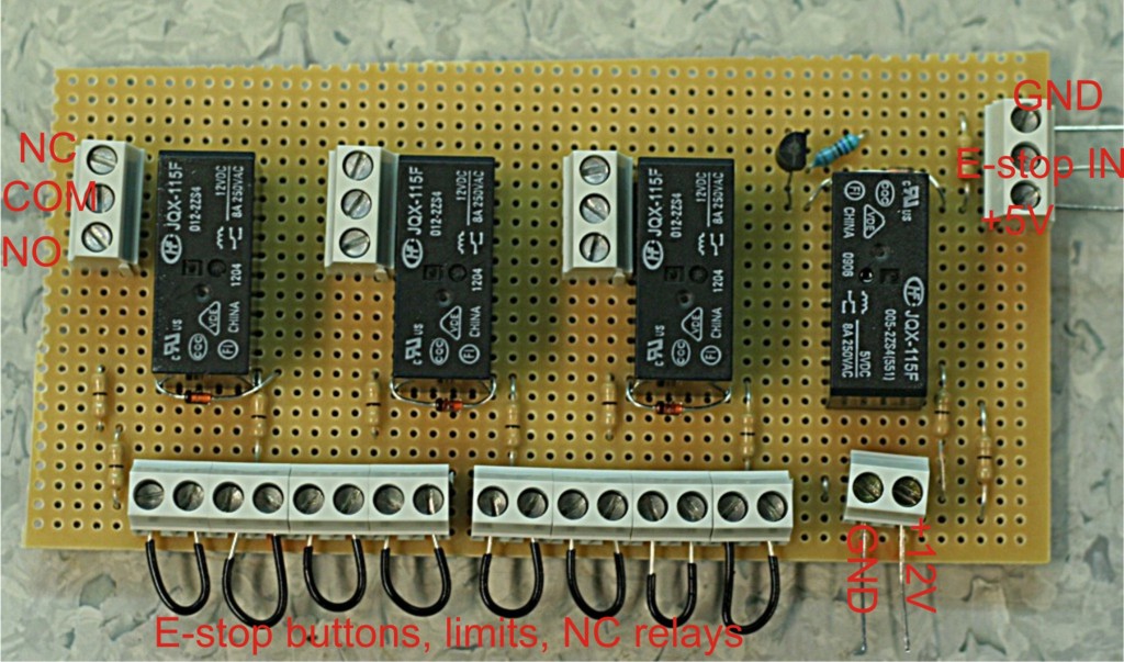
This is the E-stop circuit I am going to use when upgrading the cnc-mill to servo control. The idea is to use a wire-OR circuit (series connection of NC switches) for things that cause an E-stop followed by a wire-AND circuit (parallel connection of relays) for things I want to happen at E-stop.
The E-stop out signal from EMC is wired to the top right of this board (labeled E-stop IN...). When this signal goes high it closes the rightmost relay which has +12V wired to it. The 12 V then goes through a series of NC switches, which I've here just shorted out with the black wires. In reality the black wires will be replaced by one E-stop button on the main enclosure, one E-stop button on the jog-pendant, X/Y/Z limit switches, NC servo-amp fault relays, and a VFD NC fault relay.
When all is well +12 V is supplied to the three other relays, and these provide NC or NO outputs. One is used to tell EMC everything is OK (E-stop IN signal in EMC), one is used to enable the power switch of the axis servos, and one is spare for now.
This should make the machine reasonably safe. If any of the E-stop buttons are pressed, a limit is tripped, or the servo amps/VFD are not feeling well we should go into E-stop, and that will cut power from the servos. EMC will also notice this and I'm relying on EMC to shut down the coolant pump and the VFD.