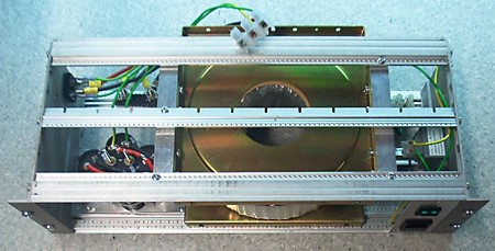
I've put together a simple unregulated power-supply for use with the DC servos that are going on the cnc-mill in the near future. The design is as simple as it gets: 230 VAC input, fuse, 2-pole switch, inrush-current limiter, 1.8 kVA toroidal transformer with twin 30 V secondaries in series, diode bridge, and finally four 10 000 uF electrolytes.
I did a load-test by hooking up various random devices I could find. It didn't exactly go as planned, since most stuff I could find is designed for 230 VAC. I had a resistor rated at 2000 W, a 500 W halogen lamp, a small oven etc. so you would think I could have gotten up to full load? But no, the stuff rated at 230 VAC doesn't dissipate nearly as much energy at 70 VDC 🙁
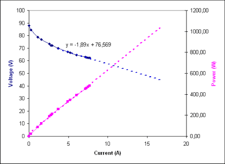
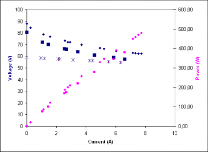
I was surprised at the largish voltage drop measured, but it's totally unregulated so something like this was to be expected. At about 7 A load I measured a voltage ripple of 1.4 V - which seems OK. A fit to the latter points show an effective series resistance of about 1.9 Ohms for the transformer. I've extrapolated my measurements with dashed lines up to around 1000 W which I estimate is the maximum we will ever use. Hopefully the voltage drop will not be problematic, since overall the system is under closed-loop control.
I hope those drives are measuring actual bus voltage and compensates the voltage change in outputs in one way or another. If it is just 'blind' PWM amplifier, then there is a trouble with changing sensitivity of servo system during voltage variation.
However, I guess that something like 30% drop could be just tolerated even with blind amplifiers but requires reduction of feedback gains to make it stable in all conditions.
I wonder if the transformer is correctly wired. Just calculate how much power loss there is to see how bad efficiency it has. Can you measure something like 1.9 ohms from secondary windings with a multimeter?
The drive is as you say 'blind' when it comes to the DC-rail voltage, and so is the PID loop running in EMC.
You have a good point. Thinking about it I expect that the gain values set at low load will be a little less than the maximum possible at high load (lower DC-rail voltage). It remains to be seen if this is a real problem in practice.
EMC is aware of the PWM commanded to the servo drive, and that is roughly proportional to the motor current. So in principle the PID gains could be adjusted based on an estimated overall load current from all three PWM values...
Two ohms for the secondary windings does seem high, but I'm not sure if some dynamic properties of the toroid come into play here also, or if it's the DC-resistance that matters. I can measure it with a mutlimeter tomorrow and comment here.
Anders
Voltage is not a very good approximation of motor current since there is a significant amount of speed dependant back EMF from motor. But I hope you get a good tuning after all!
I would test the transformer with pure resistive load for AC (no rectifier & caps). If efficiency is low, then I suspect there is something wrong. Or if secondary resistance is much lower than 1.9 ohms, it would mean that voltage drop comes from somewhere else. Maybe only a part of primary side winding is being used?
Hi again,
I measured the secondary winding resistance with a multimeter, and it is very low. The multimeter shows 0.2 Ohms when short circuited, and around 0.3 Ohms when connected to the secondary windings. So nowhere near the 1.9 Ohm effective series resistance.
In the first test above I used only one primary winding. There are two others which have very few turns. I think they are used for adjustment to either 220, 230, or 240 VAC input. Previously they were unconnected, but now I connected them all in series and did another test:
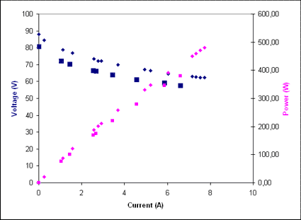
New test is the bigger squares, old is smaller diamonds. Pretty much the same I would say. So it's not that all the primary windings weren't in use.
I can do a test of the pure AC side too without rectifier and caps.
Here is the AC test, looks much better:
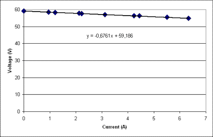
This line would give a series resistance of about 0.7 Ohms which seems more reasonable.
Still not sure what is going on here...
I can plot both the DC load-tests and the AC load test in the same graph:
That would indicate that the DC load line coincides with the AC load line when we go to higher currents.
But still the large, over 10 V drop in the DC voltage when loading it up from 0 A to 4-5 A worries me a bit.
You are missing something, what you are seeing is normal.
You have two diode drops in series with the transformer. You are NOT taking an RMS current, but only the peak current (on the peaks of the sine wave.) So your PEAK current is many times your average current.
Put a .1 ohm power resistor in series with the transformer (or diode bridge) to ground and look with a 'scope. You'll see huge current spikes (1 volt is 10 Amps.) How much drop is there with the PEAK current on your diodes and transformer?
A choke input supply will have a much better power factor, and a PFC chip will do an even better job.
AC load looks much better. Perhaps DC voltage drop is just caused by clipping of sinewave. That can happen because transformer is working only during peaks and idling the rest time. I wouldn't have imagined drop to be so drastic.