toggle2nist

EMC uses 'nist-logic' for most IO, meaning there is one on-switch/signal to switch a thing on, one off-switch/signal to switch it off, and one indicator-signal to tell you the state.

To connect momentary-on pushbuttons to EMC you need at least the toggle component, but I've found that it doesn't work that great with things that can be set/reset by other parts of EMC. For example the coolant state might be set from the AXIS checkbox, G-code, MDI, a pyVCP button, or a hardware button through halui.

I made toggle2nist to set the coolant state with a momentary-on pushbutton. The hardware button connects to a toggle, and the toggle output connects to toggle2nist. It also needs the is-on signal, and produces as outputs the on/off signals (to halui.flood.on and halui.flood.off in this case).

component toggle2nist "toggle button to nist logic";
pin in bit in;
pin in bit is_on;
pin out bit on;
pin out bit off;
variable int old_in;
variable int to_state=0;
function _;
license "GPL";
;;
FUNCTION(_) {
if (in!=old_in) /* a toggle has occurred */ {
if (is_on) { /* turn OFF if it's on */
on=0;
off=1;
to_state=0;
}
else if (!is_on) { /* turn ON if it's off */
on=1;
off=0;
to_state=1;
}
}
else {
/* reset pins when we see the desired state */
if (to_state==is_on) {
on=0;
off=0;
}
}
old_in=in;
}

idb - Inverse Deadband component for EMC2

Due to the open-loop response of my servo motors I found I need 'inverse-deadband' on the PID output to achieve a 'tight' PID loop.

The idea is that since the motors don't respond to DAC outputs between around -0.2 to +0.2 it's not a good idea to use this interval of the DAC. I'm mapping the -10 to +10 output of the PID loop to two ranges, -10 to -0.2 and +0.2 to +10, thus avoiding the [-0.2 , +0.2] interval where the amps/motors don't respond.

Comp is a fantastic tool for writing quick custom HAL components. As usual I received knowledgeable help on IRC and was able to test my 16-line idb-component within minutes.

component idb "Inverse Deadband";
pin in float in "Input";
pin out float out "Output";
param rw float amount;
function _ ;
license "GPL";
;;
FUNCTION(_)
{
if (in==0.0)
out=in;
else if (in<0.0)
out=in-amount;
else if (in>0.0)
out=in+amount;
}

PID Tunig

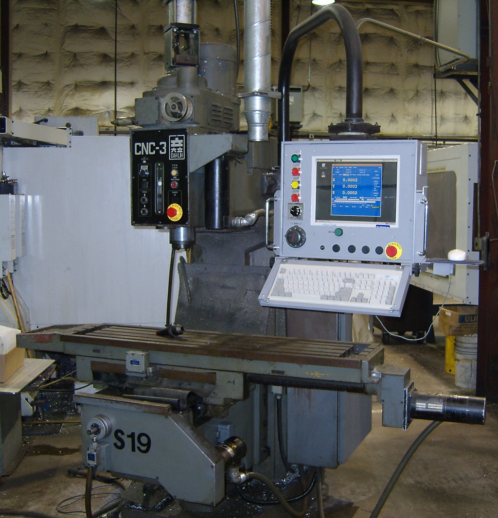
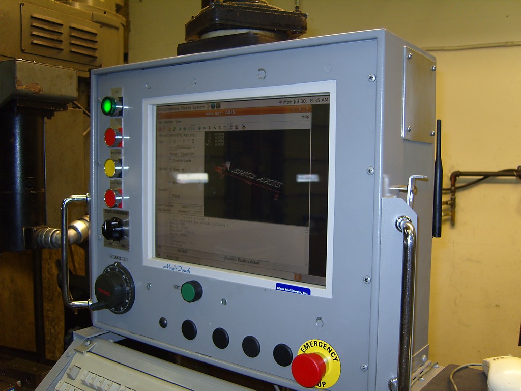
For a few weekends now I have been 'dry-running' the servo electronics that are going to replace stepper motors on the cnc mill. So far the servos are working in closed loop, I can control the VFD forward/reverse and set the RPM, I can read in a spindle-encoder to verify the RPM and also do rigid tapping. The coolant relay works. There's a jogwheel that can be used for jogging the machine or adjusting spindle/feed-override.

Still on the to-do list are limit switches, home switches and homing, improvements to the E-stop loop, and linking up some pendant buttons.

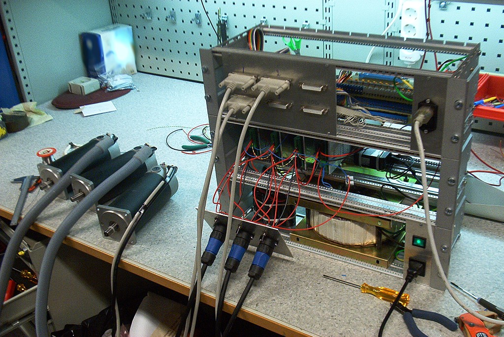
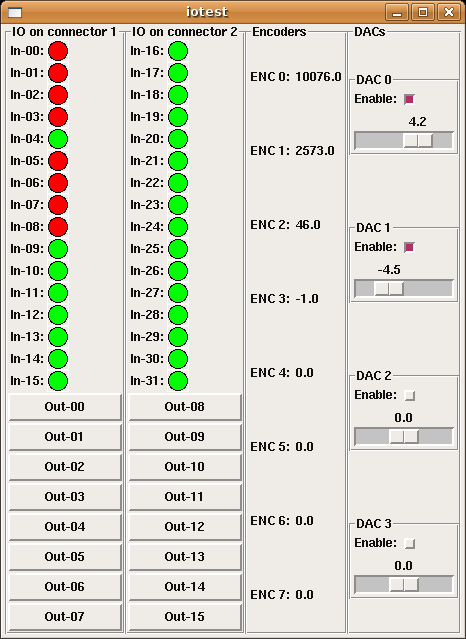
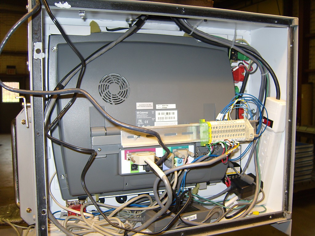
I did a little PID-tuning today with one servo motor just sitting on the bench - no load. The final PID parameters when the motor is hooked up to the machine are probably going to be different from these, but at least I got some experience with tuning. I'm using the Mesa m5i20 to read encoder counts and output PWM to pico-systems servo amplifiers. The servos have 1000-line encoders so I get 4000 counts per revolution. The ballscrews are 2.5mm/revolution, so one encoder count corresponds to 0.000625 mm.

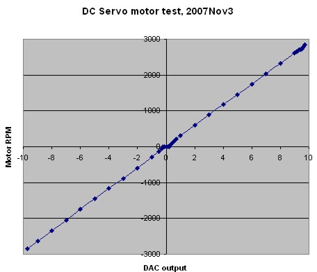
When tuning I did a 200 mm long G0 (rapid) move which allowed the motors to get up to max speed which was set to 6000 mm/min. With the servo directly coupled to the 2.5mm/rev screw that corresponds to 2400 RPM. When coasting at 6 m/min the DAC output was at around 8.7, so this is about as fast as the motors will go (unloaded). In the machine I might not be able to reach 6 m/min. Below some hal-scope screenshots that show how the pid-error changes when tuning the PID parameters.

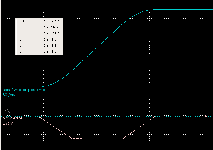
First I tried only Pgain. The error clearly shows the three phases of the EMC2 trapezoidal trajectory generator. There's an initial acceleration phase during which the error grows, then the cruise phase where it stays constant, and then a deceleration phase at the end. The following error is big, more than 1mm. Obviously I've set FERROR and MIN_FERROR quite high in my ini file so EMC2 doesn't respond with a following error and stop all motion.

Next I tried increasing the 1st order feed-forward, or FF1, parameter. That worked well, and the error is cut more than ten fold!

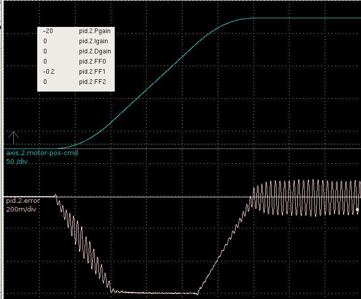
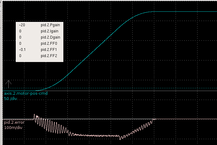
So FF1 is a good thing? More of that then! Well not quite. Here I've increased FF1 to 0.2 and get sustained oscillations at the end of the move.

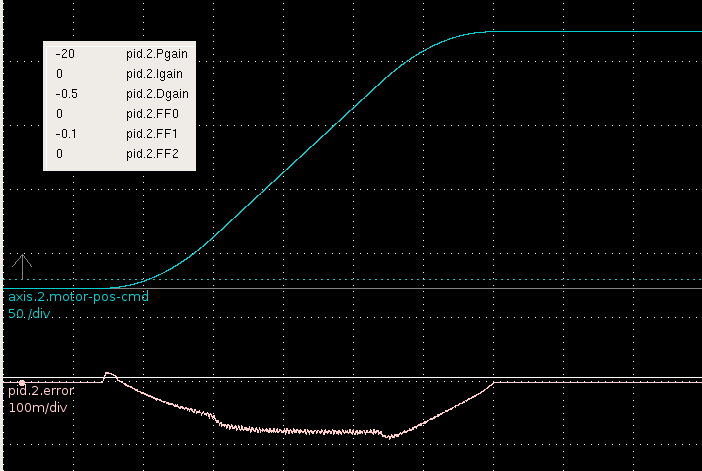
It's back to FF1=0.1 and a little D-term to the rescue for damping out the oscillations. Seems to work quite well.

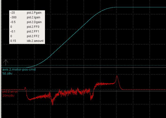
Finally I ramped up the Igain. That helps to reduce the cruise-phase error a lot, but there still remains some following error during the accel/decel phases. There are spikes at the beginning and end of the accel/decel phases which I should try to get rid of. I guess some spikes will always remain since EMC2's trajectory planner outputs a trajectory which is only once differentiable (i.e. the velocity plot has 'sharp corners', and the acceleration plot has discontinuities, see pic here). I'm also using the inverse-deadband component to compensate for the open-loop response of the motors (see next post).

The maximum error is around 0.02 mm, or ca 32 encoder counts. I'm hoping the motors will perform at least as good as this when in the machine!

Hard disks are not forever

Just had a 2-3 year old SATA drive fail on me. If you're reading this, go and take backups of critical data. Do it. Now.

This is the cnc-mill controller machine so hopefully no critical data was lost. Some notes on the EMC2 install process, just in case I need to do it all over again sometime soon...

  • Install WinXP on a 50 Gb NTFS partition
  • Installed Ubuntu 6.06LTS from CD. Manual partition, 50 Gb for root file system, 2 Gb for swap.
  • Ubuntu update manager suggests 301 updates (278M) to install. I'm in Finland, but strangely my sources.list points me to au.something servers. Reboot.
  • Install EMC2 using emc2-install.sh. Reboot.
  • 'latency-test' shows reasonable jitter values - good.
  • Configure X to enable 1280x1024 resolution: 'sudo dpkg-reconfigure xserver-xorg'. Answer lots of techy-questions, remember to add the correct screen resolution and the correct keyboard (pc102). I wasn't able to log in the first time I tried this because I had chosen an incorrect keyboard type/layout.

Spinning the DC Servos

Some good steps towards driving our cnc-mill with DC-servos taken today. I got the pico-systems servodrives wired correctly, the new 50 kHz PWM m5i20 configuration loaded onto the fpga, and updated my pyvcp test panel a bit. I'm using three 19" rack enclosures. The lower one has a 1.8 kVA transformer, the middle one houses the servodrives, and the top one has differential encoder cards for the motors and optoisolator interfaces to the m5i20.

One small setback was that the servodrives wanted the PWM in reverse polarity compared to what I had available. There's nothing in the m5i20 driver to reverse the polarity of the DAC output PWM. Fortunately the drives have optocoupler inputs so instead of GND-PWM I wired them in a PWM-Vcc configuration and it worked OK. I did an open-loop no load test (below) where I monitored the RPM while changing the DAC output. There's a bit of dead-band in the middle where nothing happens between DAC values of about -0.2 and +0.2. After that the curve is pretty linear up to +9.7 after which the PWM pulse becomes unacceptably short for the servodrive and at DAC=9.8 or above the motors just jump and stutter. So eventually with EMC and PID control I need to limit the DAC range to [-9.7 , +9.7].

Next is probably trying out closed-loop PID control, and after that I need to look at the E-stop chain, home switches, a relay for the flood coolant pump, and controlling the VFD/Spindle.

pyVCP m5i20 HOSTMOT-4 test panel

For testing the servo-drives and all the electronics I found this test-panel for the HOSTMOT-4 conifiguration of the m5i20 quite useful.

It uses an XML file (iotest.xml) to define the pyVCP panel layout, and then a HAL file (pyiotest.hal) to hook up the IO pins of the m5i20 to the panel. I'm also using a shell script (iotest.sh) to start the realtime environment and run pyvcp followed by the HAL file automatically.

Compare this to my earler effort with the old VCP. Now with many more widgets in pyVCP I have better control of the DACs etc.

Dah-Lih EMC2 conversion

Stuart Stevenson wrote about his Dah-Lih EMC2 conversion on the emc-mailinglist, and has allowed me to publish these pictures of his mill. I've scaled the pictures to 1024 pixels wide - click the picture to see it in high-resolution.

Machine after conversion.

Machine before conversion. Pendant has original CRT and buttons.

Control electronics. Jon Elson's PPMC cards at the top.

Relays and transformers.

The new control. The computer is a Gateway Profile 3.

There is a MagicTouch touch screen mounted in front of the computer.

Back side of control. The computer is connected to the PPMC cards by the parallel port only. Jog-wheel and buttons are wired directly to PPMC. The network cable goes to a Linksys WET11 bridge mounted on the back panel.