Here's an old-school PID controller based on simple op-amp circuits that I put together a week or so ago.
Here's an old-school PID controller based on simple op-amp circuits that I put together a week or so ago.
Update: this version of the component may compile on 10.04LTS without errors/warnings: frequency2temperature.comp (thanks to jepler!)
There's been some interest in my 2-wire temperature PID control from 2010. It uses one parallel port pin for a PWM-heater, and another connected to a 555-timer for temperature measurement. I didn't document the circuits very well, but they should be simple to reproduce for someone with an electronics background.
Here's the HAL setup once again:

The idea is to count the 555 output-frequency with an encoder, compare this to a set-point value from the user, and use a pid component to drive a pwm-generator that drives the heater.
Now it might be nicer to set the temperature in degrees C instead of a frequency. I've hacked together a new component called frequency2temperature that can be inserted after the encoder. This obviously required the thermistor B-parameters as well as the 555-astable circuit component values as input (these are hard-coded constants in frequency2temperature.comp) . Like this:

I didn't have the actual circuits and extruder at hand when coding this. So instead I made a simulated extruder (sim_extruder) component and generated simulated 555-output. Like this:

This also requires a conversion in the reverse direction called temperature2frequency. A stepgen is then used to generate a pulse-train (simulating the 555-output).
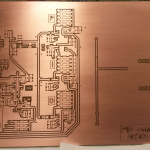
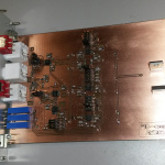
"heartyGFX" has made some progress on this. He has a proper circuit diagram for the PWM-heater and 555-astable. His circuits look much nicer than mine!
The diagrams above were drawn with Inkscape in SVG format: temp_pid_control_svg_diagrams

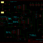
We hooked up the temperature measurement circuit and the PWM-amplifier to EMC today and tested PID-control of the extruder head temperature. The ini, hal, and xml files for this are here: temp_control_pid.tar
It's probably much easier to figure out the connections from the diagram below than to browse the text files. The square wave, which has a frequency proportional to the temperature, comes in on parallel port pin-13, and is connected to an encoder. The encoder has a velocity output which will be equal to the frequency of the square wave in Hz. This frequency is used as the feedback for a PID-component which compares the measured frequency against a set-point which is taken from a pyvcp slider. The pid output is used as an input to a pwm-generator, whose output needs an inverter, since the pwm-amplifier is active-low. The PWM is output on parallel port pin 9.
I wish there was a tool which would draw these HAL/pyVCP diagrams automagically from the source files. There is some work in that direction already: crapahalic and HAL with gschem.

I mounted a servo on the x-axis of the mill today and did some PID tuning. The video shows a ca 300mm rapid move at 5500mm/min (217 IPM). Below some hal-scope views of what's going on in the PID loop during the move.
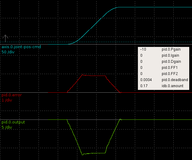
Here only P-gain is used and the machine needs to lag behind the commanded position (blue) a bit (slightly less than 1 mm, red trace) for the DAC output (green) to reach to reach the required level.
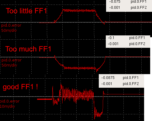
The lagging behind is curable with FF1, 1st order feed-forward. FF1 adds to the DAC output in proportion to the commanded velocity. With too little FF1 (top, note scale for red trace is 20x finer than in the first pic) the machine still lags behind. Wit too much FF1 (middle) the machine leads commanded position, and I figure the bottom trace has about the right amount of FF1 since the error is small and symmetrical around zero during the 'cruise'-phase (constant velocity) of the move.
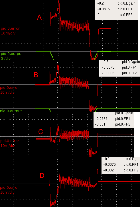
I found FF2 much more tricky. Note again the scale is finer than before (100x finer compared to the first pic!). FF2 is 2nd order feed-forward and adds DAC output in proportion to the acceleration of the commanded position. In A there is no FF2 and the machine lags during acceleration and leads during deceleration. In B I've added FF2 and the error during acceleration seems to be a bit better. C has more FF2 and both the acceleration- and deceleration-phase errors are better. Then in D it seems I've overdone FF2 since the acceleration-phase error gets much worse (machine is leading commanded position), while the deceleration error improves.
I'm confused. What could be asymmetric so that FF2 acts differently during acceleration and deceleration? I should add that I am using an m5i20 to generate PWM for pico-systems servodrives (basically a H-bridge). There is no motor current, motor voltage, or velocity feedback, only feedback from a 4000 pulse encoder. The ballscrews are 2.5 mm/rev so one count is 0.000625 mm. The peak error during acc./dec. in the FF2 figure above is around 0.01 mm or 16 encoder counts. During cruise-phase the error is smaller, maybe only +/- 8 counts.
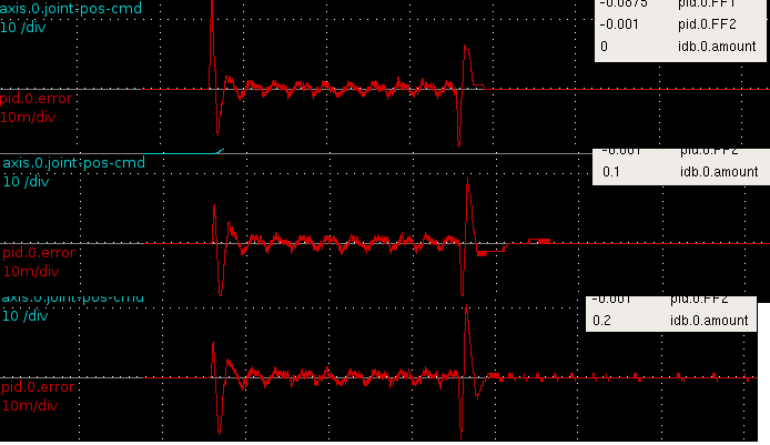
I then tested the inverse-deadband component which is supposed to linearise the DAC-motor system. I'm not sure what these results mean yet. The first error-peak is lowered, but there's an opposite effect during deceleration. This is a slower move and shows some periodic error during the cruise-phase, I wonder what that could be?
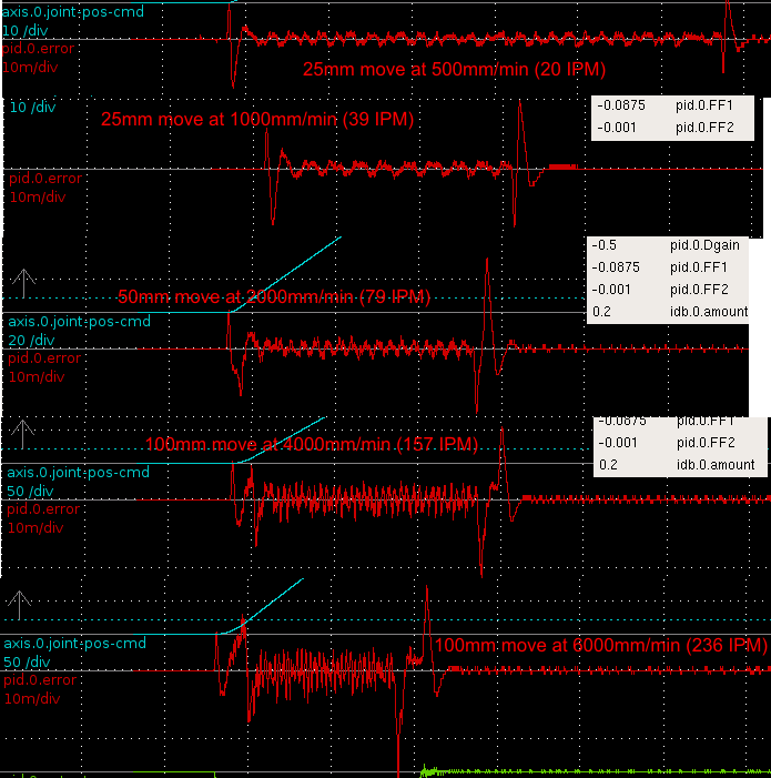
Finally some traces recorded with different length moves and different feed-rates. In reality 1000 mm/min is about the highest feed-rate used while machining, and everything higher than that is mostly for show only 🙂
Clearly higher feed-rates are more difficult for the PID loop. The acceleration/deceleration phases are still difficult, and there remains an asymmetry where with the current PID-parameters the acceleration phase works a bit better than the deceleration phase. I think with another choice of FF2 that could be reversed so that deceleration is fine but there is more error during acceleration.
I wonder if there is something peculiar to only torque-mode servo PID-loops that I should take into account? Something to do with the asymmetry between acceleration/deceleration...
For a few weekends now I have been 'dry-running' the servo electronics that are going to replace stepper motors on the cnc mill. So far the servos are working in closed loop, I can control the VFD forward/reverse and set the RPM, I can read in a spindle-encoder to verify the RPM and also do rigid tapping. The coolant relay works. There's a jogwheel that can be used for jogging the machine or adjusting spindle/feed-override.
Still on the to-do list are limit switches, home switches and homing, improvements to the E-stop loop, and linking up some pendant buttons.
I did a little PID-tuning today with one servo motor just sitting on the bench - no load. The final PID parameters when the motor is hooked up to the machine are probably going to be different from these, but at least I got some experience with tuning. I'm using the Mesa m5i20 to read encoder counts and output PWM to pico-systems servo amplifiers. The servos have 1000-line encoders so I get 4000 counts per revolution. The ballscrews are 2.5mm/revolution, so one encoder count corresponds to 0.000625 mm.
When tuning I did a 200 mm long G0 (rapid) move which allowed the motors to get up to max speed which was set to 6000 mm/min. With the servo directly coupled to the 2.5mm/rev screw that corresponds to 2400 RPM. When coasting at 6 m/min the DAC output was at around 8.7, so this is about as fast as the motors will go (unloaded). In the machine I might not be able to reach 6 m/min. Below some hal-scope screenshots that show how the pid-error changes when tuning the PID parameters.
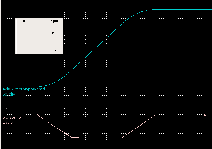
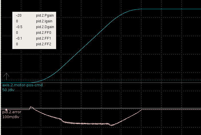
First I tried only Pgain. The error clearly shows the three phases of the EMC2 trapezoidal trajectory generator. There's an initial acceleration phase during which the error grows, then the cruise phase where it stays constant, and then a deceleration phase at the end. The following error is big, more than 1mm. Obviously I've set FERROR and MIN_FERROR quite high in my ini file so EMC2 doesn't respond with a following error and stop all motion.
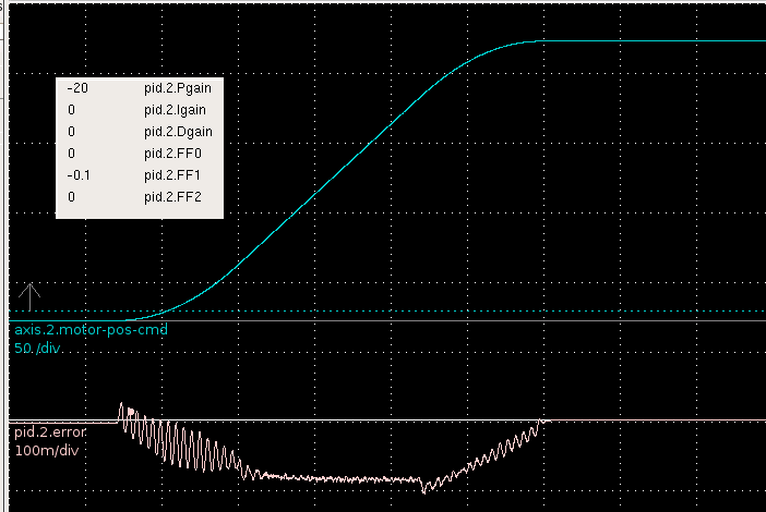
Next I tried increasing the 1st order feed-forward, or FF1, parameter. That worked well, and the error is cut more than ten fold!
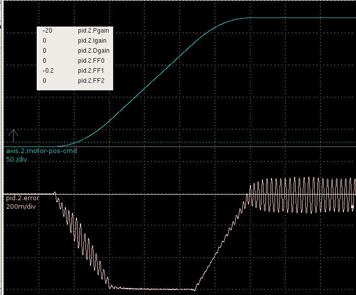
So FF1 is a good thing? More of that then! Well not quite. Here I've increased FF1 to 0.2 and get sustained oscillations at the end of the move.
It's back to FF1=0.1 and a little D-term to the rescue for damping out the oscillations. Seems to work quite well.
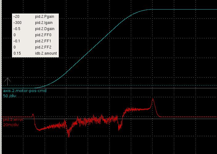
Finally I ramped up the Igain. That helps to reduce the cruise-phase error a lot, but there still remains some following error during the accel/decel phases. There are spikes at the beginning and end of the accel/decel phases which I should try to get rid of. I guess some spikes will always remain since EMC2's trajectory planner outputs a trajectory which is only once differentiable (i.e. the velocity plot has 'sharp corners', and the acceleration plot has discontinuities, see pic here). I'm also using the inverse-deadband component to compensate for the open-loop response of the motors (see next post).
The maximum error is around 0.02 mm, or ca 32 encoder counts. I'm hoping the motors will perform at least as good as this when in the machine!