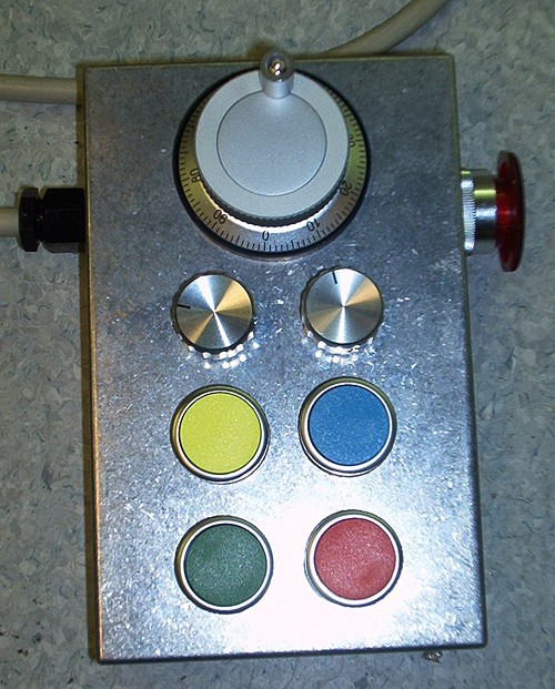
One part of our continuing CNC-mill upgrade is to connect a jog-pendant to the mill which will enable jogging and some other manual controls in EMC2. Here are some pictures and notes of the present status.
Hardware
For I/O I'm using a M5i20 PCI card by Mesa Electronics, but most of the jogwheel hardware and HAL code will be the same regardless of I/O method (the parallell port, or another motion control PCI card could be used).
Jogwheel: I got my jogwheel, a 100 ppr Micronor, via ebay. It has 100 pulses per revolution, with a detent at each position, works with 5 V DC, and has differential encoder outputs (+A, -A, +B, -B). To save I/O pins, I first decode the differential signals to single-ended ones using a DS3486.
The single ended jogwheel signals are connected to the M5i20 and will show up as pins m5i20.0.in-09 and m5i20.0.in-10 in HAL.
6-position rotary switch: This switch controls what effect movement of the jogwheel. There are six positions: X-jog, Y-jog, Z-jog, OFF, Feed Override, Spindle RPM Override. To save I/O pins, the position of the 6-pos switch is encoded with an SN74HC148 into a 3-bit value.
The 3-bit position information is connected to pins m5i20.0.in-00, m5i20.0.in-01, and m5i20.0.in-02.
3-position rotary switch: control of the jog increment, i.e. how much, in mm, an axis is jogged for each count on the joghweel. The settings are 0.1 mm, 0.01mm, and 0.001mm. When turning the wheel by hand at a moderate pace, these settings result in jog-feeds of about 500, 50, and 5 mm/min respectively, which sounds about right.
Figuring out where the three position switch is requires two bits, they are at m5i20.0.in-03 and m5i20.0.in-04.
4 Pushbuttons: These pushbuttons control coolant on/off (blue, m5i20.0.in-06), spindle on/off (yellow, m5i20.0.in-XX?), and program execution (red=pause m5i20.0.in-XX?, green=play/step m5i20.0.in-XX?)
E-stop: An E-stop button is included in the jog-pendant, and its electrical circuit is completely separate from the rest of the jogwheel signals. It will be included in an E-stop chain which when broken will cut power to all motor drives.
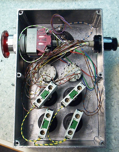
Black backside of jog wheel hidden behind wires and E-stop button at the top. White rotary switches in the middle, with the pushbuttons in the lower part of the box. I used an old 25-wire parallell port cable for wiring.
HAL
HAL is EMC2:s Hardware Abstraction Layer, which let's you very flexibly link together EMC with external hardware (motor drives/encoders, coolant, jog-wheels, tool changers etc.etc.).
I've placed all of the HAL related to the jogwheel in a file called jog.hal, which I enable to be run each time EMC is started by adding the following HALFILE command to the list in the [HAL] section of my ini:
HALFILE = jog.hal
If besides jogging the machine you want to control some other stuff, you will also need halui. Enable it by adding the following line to the ini (again in the [HAL] section):
HALUI = halui
All of this is tested with a recent HEAD version (pre-2.1) of EMC2, so it might not work with the current released version (2.0.4).
I understand there is work in progress which aims to create a graphical user interface for HAL where you can drag and drop components to create your connections and logic (something like LabView/Simulink). That work is not ready however, so the only way to really understand the code is to read and hopefully understand the HAL file (downloadable above). However, here's a short description of what the code does:
Jogwheel A and B signals joga, jogb are first connected to a software encoder component which produces an integer number counts. This number is wired to all the places where it is going to be used: axis.0.jog-counts, axis.1.jog-counts, axis.2.jog-counts, halui.feed-override.counts, and halui.spindle-override.counts.
Then there is code for the jog increment selection: pins axis.0.jog-scale, axis.1.jog-scale, and axis.2.jog-scale are fed with a number (0.1 0.01 or 0.001) which comes from a mux4 component controlled by the increment selector rotary switch bits (inc1 and inc2).
After that we need to select which axis/parameter we are going to jog. This is determined by the three bit pattern from the 6-position rotary switch. My solution is not elegant, but it works: For each function (Xjog, Yjog, Zjog, FO, SO) there's a separate match8 component that will output an enable bit to the appropriate pin (axis.0.jog-enable, axis.1.jog-enable, and axis.2.jog-enable) when the selector bit-pattern is right.
The halui functions I'm using (feed-override.counts and spindle-override.counts) don't have enable inputs, so I'm switching halui.feed-override.scale and halui.spindle-override.scale between values of 0.01 (enabled) and 0.0 (disabled) using two mux2 components.
Finally the push-buttons. EMC was created using something called 'NIST-logic' where each property (like flood coolant) has three pins: flood.on, flood.off, flood.is-on), the first two are used for turning on or off coolant, and the third pin indicates the current flood status. So the simplest thing to do in hardware is to match this logic: one button for on, one button for off, and a lamp/LED for indicating on or off. I thought this was a waste of I/O and I don't want lamps/LEDs since I can look at the EMC screen to see that. So my buttons are momentary on pushbuttons, which makes it a bit harder to implement the HAL code...
First it seems simple, use an and block to detect if flood.is-on is true and the button is pressed, then turn flood off.
If flood.is-on is false (flood is off) and the button is pressed, do the opposite, turn flood on.
This simple scheme has however the undesirable effect that if the button is held pressed down for some time, flood will oscillate between on and off. My prelimiary solution is an ugly 1 second delay for the status feedback to the and components. It works as long as the button is not held down for more than 1 second (and you can't switch on/off flood faster than 1 second). Better suggestions are welcome !
PS. for reference, let's also document the 25-pin cable pinout I'm using (I know, my handwriting sucks...).
Thank you for posting your HAL file, I'm not as proficient as you obviously
are with EMC2 but I hope that this will help me.
Dave.
Besides the mailing list, a very good place to get help with EMC is on IRC. Details at:
http://www.linuxcnc.org/index.php?option=com_content&task=view&id=4&Itemid=8&lang=en
Can you do rising edge events in HAL? That way the coolant will only toggle each time the button is actually depressed.
Hi Tony,
Yes I think quite recently a new HAL component 'edge' was implemented, but I have not tested it yet.
Anders
Manfredi asked if a normal rotary encoder can be used as a jogwheel, and how I decode the differential signals with a DS3486
My reply:
Hi Manfredi,
The benefit with a purpose-made joghweel is that it has detents, i.e. it will stay at the position you leave it. A normal rotary encoder would work, but it would not be as nice to use.
A quick-and-dirty way of using differential encoder signals is to just use the +A and +B signals (leave the -A and -B signals unconnected).
If you really want the added noise immunity offered by differential signals then you need the DS3486 circuit or something similar.
The circuit I am using is from an IRF datasheet/application note.
http://www.irf.com/technical-info/refdesigns/dg-irmck201.pdf
see the next to last page.
Anders
I've been looking at the HAL tutorial for EMC2 and, even with that, I still can't follow the jog.hal program. How do people go about becoming proficient in HAL (documentation, trial and error, etc)?
Williams
Hi Williams,
HAL is very much like building real electronics, so a degree in electrical engineering can't hurt 🙂
There should be some tutorial with siggen and halscope in the manual, did you go through that? Also learn to use halmeter.
Jeff Epler recently worked on visualizing a HAL circuit. That might help you see how everything is connected:
http://axis.unpythonic.net/01174426278
pyVCP should be ideal for learning to build easy HAL circuits and testing them. Maybe someone should make a set of tutorials using pyVCP and HAL?
Anders
Anders,
I do a lot of PLC programming and in that world I would use the logic
Button On if output is off latch it on else if output is on latch it off. Don't know if this helps in any way with your coolant issue. Is the input being reevaluated some how at certain intervals?
Trying hard to understand your jog.hal file. Your using the pins m5i20.0.in-00, 01, 02 as your selection inputs which gives you eight possible combinations. The match8 sections for each axis is the same except for the match8.x. How does HAL make a match based on the inputs? Is it converting the inputs to BCD?
Thanks for the information on the pendant control.
John
Hi John,
EMC contains a software PLC, classicladder, which I'm sure could be for the functionality I want - I just haven't had time to look at this for a while.
You have most of the idea right for my rotary switch HAL. The rotary switch has six positions which are encoded by the SN74HC148 into a three-bit value. In theory those three bits can be in eight different states, but as the switch only has six positions only six of those states are used.
I use a match8 block to detect which state we are in. The match8 block has two 8-bit inputs, and will output a true signal if those two 8-bit inputs are identical.
So for one function, say X-jog, I decide it's going to be on when the 3-bit patter is for example 1-0-1. I then hard-wire constant 1s and 0s to one input of a match8 block, and the SN74HC148 to the other input. So now this particular match8 block will show a true output only when the rotary switch is in the 1-0-1 position.
There's a corresponding match8 block for each of the other functions where the other 8-bit input is just hardwired to a different constant state 0-0-0, 0-0-1, and so on.
No BCD involved, just raw matching of bit-patterns. The output of the match8 block is then used as an enable for jogging etc.
Anders
Thanks Anders,
Now I see in the file where you are using "sets" and "linksp" to set the match pattern for the match8.x.bx.
Will the jog wheel function while in motion?
Thanks for the information.
Anders
Many thanks for listing the pendant info.
I did the 3d_chips.ngc gcode demo file thats in emc many years ago,and I am finally trying a emc based servo control with the mesa 5i20 / 7i33 / 7i37 over in the UK
I wandered which 5i20 inputs you used for the Pushbuttons: spindle on/off (yellow, m5i20.0.in-XX?), and program execution (red=pause m5i20.0.in-XX?, green=play/step m5i20.0.in-XX?) and if you have a diagram of the selector switch logic for the pendant.
Regards Gary
BigJohnT:
(re jogging while in motion) the jogging commands will only be accepted by EMC when in the manual/jogging mode. EMC just ignores any motion of the jogwheel if you are running a program (or in MDI mode)
GaryDrew:
All the m5i20 inputs are essentially identical, so it doesn't matter to which input number you wire a switch as long as your HAL configuration has that same number. Once the signal is in HAL it can then be wired whichever way you like to the motion-controller or other parts of EMC.
I don't have a diagram for the selector switch. The 8-to-3-line decoder is used just to save pins, it could easily be left out of the design and the 6-pos selector switch would then use 6 input pins on the m5i20.
If you look at the datasheet:
http://focus.ti.com/docs/prod/folders/print/sn74hc148.html
there is a truth-table on p. 2 which should explain how it works. You pull any of the inputs low, and a corresponding bit-pattern will be output on the three output-pins. That is easily wired by having pull-up resistors on all the inputs, and then having the 6-pos switch ground one of inputs 0 to 5.
HTH,
Anders
for connecting the buttons to halui I've now created a new component:
http://www.anderswallin.net/2008/04/toggle2nist/
Hi,
Even though your MPG jogwheel produces differential outputs via A+,A-,B+,B- you can use them as single ended outputs by ignoring the A-,B- outputs and just use the A+, B+. Eliminating the need for theDS3486.
Cheers,
Peter.