Offset Ellipse

Continuing with some random thoughts on CAM algorithms, here's a diagram I drew in response to a question on offset ellipses posed by Julian Todd.

(click image for high-resolution version)
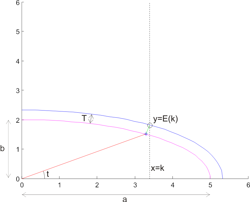
The task is to find an offset ellipse to a given ellipse (magenta). The offset ellipse (blue) should lie a distance T, measured along the normal to the ellipse (I've drawn one normal of length T in green), from the original ellipse. Drawing the offset ellipse is simple, but it's a bit harder to find a point on the offset for a given x-coordinate x=k. I've marked this point with a circle, and its coordinates are (k, E(k)), so E(k) is a function that returns the sought y-coordinate.

I took Julian's advice of using a numerical method with respect to the geometry (not neccessarily cartesian coordinates), and parametrized the ellipse as a function of an angle t. So points along the ellipse lie at:

ex=a*cos(t)
ey=b*sin(t)

Where a and b are the major and minor axes of the ellipse, and t is an angle between 0 and 2pi. At every point there's a normal vector

nx = b*cos(t)
ny = a*sin(t)

To find points on the sought offset ellipse, we need to scale this normal so it's length is T. Each normal has a length

l=sqrt(nx^2 + ny^2)

So the sought normal vector is

nx_T = (nx/l)*T
ny_T = (ny/l)*T

or more explicitly

nx_T = ( b*cos(t) / sqrt((b*cos(t) )^2 + (a*sin(t))^2) ) * T
ny_T = ( a*sin(t) / sqrt((b*cos(t) )^2 + (a*sin(t))^2) ) * T

Now, points on the offset ellipse lie at

oe_x = ex + nx_T
oe_y = ey + ny_T

and we need to find the particular t angle which results in a point (oe_x, oe_y) for which oe_x = k holds. Inserting the above expressions, this happens when:

(a+T*b/sqrt( ( b*cost(t) )^2 + ( a*sin(t) )^2 ))*cos(t) -k = 0

I haven't looked for an analytic solution to this equation, but plotting it for a few test cases seems to indicate that it's fairly 'benign', and Matlab's fzero function finds a solution very quickly. If we call the solution to this equation tk, the sought point on the offset ellipse is

E(k) = oe_y(tk)

Here are two Matlab scripts I used to plot this figure: ellipsetest.m is the main program, and oe.m is used when solving the equation.

Defining a milling cutter

Some discussion over at the freesteel blog about defining a general purpose milling cutter shape in a CAM program.

I made this diagram (which hereby is in the public domain) to make it all clear in my head:

(click image for svg file)

It shows one half of the cross-section of the cutter (the axis of rotation is at the right edge of the image). There's a cylindrical part of height ha with radius a, a conical part of height hc that tapers down to radius c, and finally toroidal part of height hf.

The idea is that by writing all CAM algorithms to deal with this tool shape, nothing has to be changed when locating cylindrical, conical, ball-end, or bullnose cutters against the model. All these cutter shapes are different variants of this general shape.

A general purpose CAM program would test this cutter shape against a triangulated model. There are four surfaces on the tool, s1, s2, s3, and s4. These all need to be tested agains the model. There are also three edges (e1, e2, and e3), but only e1 needs to be separately checked against the model since if e2 or e3 were touching the model, so would the adjecent surface.

Compression strut for Gooseneck

Two new parts for the gooseneck: a compression strut from Sails ETC, and a DIY mast-ram.

The compression strut fits the lower end of the gooseneck (bottom left), and if you bend it a little bit, it will fit a Sails ETC eyebolt too (far right) - which I plan to use on the boom. The mast-ram consists of a plastic fitting (Maritim) that grabs the mast, a stainless steel M4 bolt (I need to open the plastic fitting a little so the head of the bolt sinks into the plastic). A brass M4 thumbwheel (Ruuvikulma) provides adjustment.

WordPress 2.1

I've upgraded to the latest WordPress, release 2.1

Hopefully everything works as before.

Funnily, the biggest new thing (besides 'boring' security fixes) advertized with 2.1 is a new visual editor for posts. But to my surprise I found it was not enabled by default! In the admin panel you need to go Users/Your Profile and check the "Use the visual editor when writing" tickbox to get the new and improved editor.

There's also a new spell-checker, but for me it errors out with a cryptic message "Could not execute AJAX call, server didn't return valid a XML."

For some reason I also needed to replace my <code>.htaccess</code> file for everything to work.

Update: I'm still finding it quite annoying that WordPress creates posts with no ALT tag when I insert images and don't bother to include some text in the ALT field. This results in errors when doing XHTML validation. So I've filed a WordPress bug report. Let's see what happens!

Tweaking the header

Some notes, mostly for myself, about how I chaged the header image and the way the title is displayed. I bet this will be usefull after the next WordPress update when the theme most likely gets reset back to default.

To get a header image that 'rotates' i.e. is updated with a new random picture each time the page is loaded, I used Matt Mullenweg's simple rotate script. I named it rotate.php and placed it in wp-content/header-images/

I then placed the images I want as headers into wp-content/header-images/ and modified the CSS stylesheet for my theme:

#header {

background: #73a0c5 url('http://www.anderswallin.net/wp-content/header-images/rotate.php') no-repeat  center;

}

Note that some browsers (Firefox!) are smart enough to cache the header image, so if you want to see a new header pic simply pressing the 'reload' button won't do - you need to do a full reload of the page by pressing Ctrl-F5. This is not necessary using Internet Explorer

Also, from the default layout of 4em size and centered alignment, my blog title is now a bit smaller and positioned in the top left corner (so as not to obstruct the nice header pic!):

h1 {

font-size: 3em;

position: absolute;

text-align: left;

bottom: 150px;

text-indent: 0.8em

}

Update: I've made a Photo page with all the banner images and short descriptions.

Enclosure for servo electronics

I've bought three 19" rack enclosures from fellow cnc-enthusiast Jiri K:

My plan is to house the PSU, based on a 230 VAC to 2x30 VAC 1.8 kVA transformer, in the bottom box (I might have to extend the encolsure a little, the transformer should the same as Sauli J:s transformers, about 220x220x120mm). The middle box will have the servo amplifiers, and the top box will contain the optoisolators and some low-voltage logic. The top box connects to the m5i20 card in the computer via three 50-pin ribbon cables.

Together with Jari we made some panels for the servo box (bottom), and the logic box (top). The servo amps connect to the motors through the round black 7-pin connectors. Each pin is rated for 7.5 A, so I might use two pins per pole just to be safe. The logic box has six D25 connectors: four for encoders (X, Y, Z, and Spindle), one for the jog pendant, and one for limit switches (we'll have to make a separate Y-cable or something for those). There's an E-stop switch to the right, and a connector+switch for AC mains.

Here I've mounted three PWM servo amplifiers and one PWM switch from pico-systems to the back of the servo box. Secured to the back rails of the box by four M3 screws to the heatsink. The 120x120 mm fan is probably a bit overkill - but overkill is fine when it comes to cooling. At the top you see the back of the motor connectors.

More pyVCP Widgets

Since last Monday, I've been adding to the range of available pyVCP widgets:

Spinbox:

Jeff Epler suggested that my initial 'jognumber' would be better implemented with a Tkinter spinbox. It sets the value of a FLOAT by either pressing the up and down arrows, or using the mouse-wheel.

Radiobutton:

This widget creates a number of BIT pins and sets only one of them, corresponding to the checked box, true.

Jogwheel:

This resembles a real jog-wheel, and outputs a FLOAT count corresponding to the position of the wheel. The wheel rotates either by dragging with the mouse, or by rolling with the mouse-wheel. The number of counts is adjustable, 50 cpr shown in the pic I think. This will be useful for debugging jogwheel code to be used with real jogwheels, but could also find other use in pyvcp panels.

Meter:

A traditional dial-indicator, used for displaying a FLOAT. The start and end values are user-configurable.

Gooseneck prototype

We've been designing a ball-raced gooseneck for the new Noux boats. Jari sent me some pictures of his progress.


These pieces are mounted around the mast. There are two sizes, for either 12.4 mm or 11 mm Easton masts. The smaller hole is 6 mm in diameter and fits a flanged miniature ball bearing.

This piece goes on the bottom of the gooseneck axis. It has a raised ring towards the bearing, so that it makes contact only with the rotating part of the bearing.

Here's the first assembled prototype, with bearings fitted to the parts shown in the top picture. A 6 mm diameter aluminium rod forms the axis of the gooseneck. The rod is drilled and tapped with M3 threads in both ends. At the top, a Sails ETC flat eyebolt screws into the axis. At the bottom, the part shown above is secured with an M3 screw. We're hoping that the eyebolt at the top will fit the standard Sails ETC mainboom front end fitting.

We've not come to a final decision on a variable-length compression strut or kicking strap yet... The standard Sails ETC fitting works, but it attaches to a hole in the boom, which over time tends to corrode and wear into an oval shape. Bright ideas required 😉