Some discussion over at the freesteel blog about defining a general purpose milling cutter shape in a CAM program.
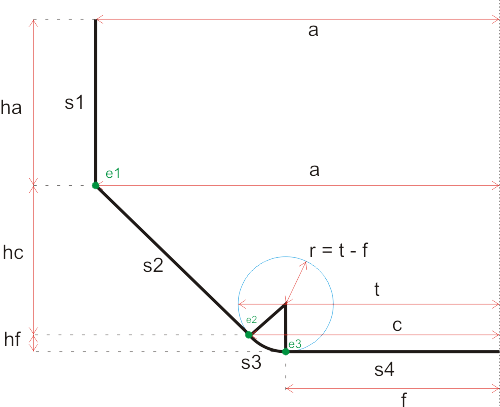
I made this diagram (which hereby is in the public domain) to make it all clear in my head:

(click image for svg file)
It shows one half of the cross-section of the cutter (the axis of rotation is at the right edge of the image). There's a cylindrical part of height ha with radius a, a conical part of height hc that tapers down to radius c, and finally toroidal part of height hf.
The idea is that by writing all CAM algorithms to deal with this tool shape, nothing has to be changed when locating cylindrical, conical, ball-end, or bullnose cutters against the model. All these cutter shapes are different variants of this general shape.
A general purpose CAM program would test this cutter shape against a triangulated model. There are four surfaces on the tool, s1, s2, s3, and s4. These all need to be tested agains the model. There are also three edges (e1, e2, and e3), but only e1 needs to be separately checked against the model since if e2 or e3 were touching the model, so would the adjecent surface.