A progress update on the building of the second generation Noux IOM - by Olof Ginström and Anders Wallin.
Hull
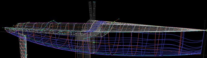
The lines of the hull have not chaged. It's still the same design from 2002 which is loosely based on the Triple Crown and a bunch of other design I have in my computer.
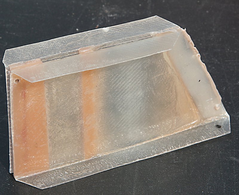
We are now moulding the hulls with three layers of 163g/m2 twill-weave glassfiber first wetted out on a flat table and then fit into the mould by hand. We've again heat-cured the hulls which unfortunately has resulted in "print" appearing on the mould and hull surfaces. I think we've now finally learned that glassfiber moulds cannot be heat cured - it will damage them whatever the heat resistance of the mould resin/gelcoat is advertized to be...
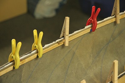
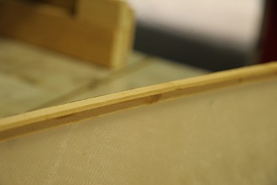
The deck is joined to the hull with a traditional wooden plank all along the join. Here we are gluing first one 3x8mm abachi strip along the hull and then one at 90 degrees.
![]()
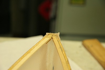
As a general principle we've found that it's much better to try to concentrate as much of the building as possible into as few phases as possible. So this time around we are moulding the bow and transom at the same time as the hull (in 2002 we did not). It's a bit more complicated and fitting the glass to the bow can be quite fiddly - but it results in a ready hull directly from the mould. Above the transom and bow are reinforced with abachi.
Deck
Apart from building techniques and more attention to detail, the biggest change for mk2 of the Noux is the deck. We're trying a two-part cockatoo style deck, which I've written about earlier.
The deck moulds are unfortunately not ready yet so I will have to come back to them later...
Finbox
Another change we wanted to do was to have more room to adjust the position of the mast. So we designed a new finbox wich should have plenty of adjustability. We did not want to carry a whole lot of water in the mastbox, so we made it only 5mm thin. That means that least on the mk2 prototypes the mast will have to be extended with a 5mm aluminium piece which goes from deck-level to the bottom of the hull. For mk3 we will hopefully have found the optimal mast position and a more conventional mastbox with one mast position but allowing rake adjustments can be used.
Fin/Rudder
We are going to use the proved 85mm chord 6% T/C NACA fin for which we have aluminium moulds. Here are a few fins, to the left an epoxy-microballoon core which is moulded first. The skins are 200g/m2 plain weave carbon laid out at 45 degrees and inside of that is about 400g/m2 of unidirectional carbon laid out along the length of the fin. Epoxy mixed with fumed silica works well as a transparent gelcoat.
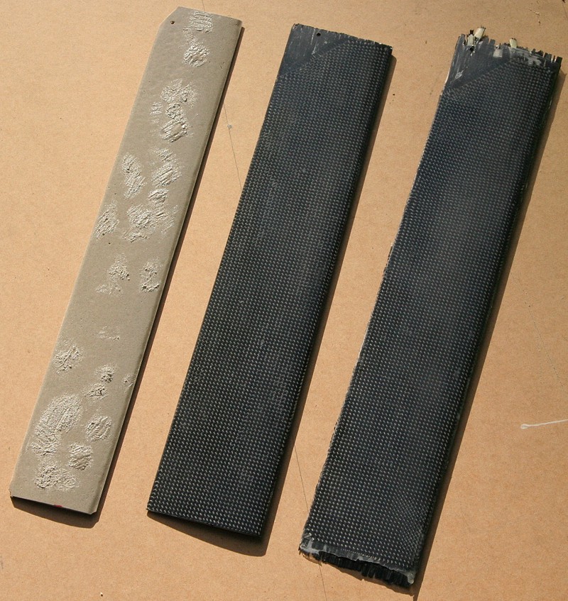
We're moulding both the fin and the rudder with the same principle. First a core of epoxy-microballoons is made, then the skin-layup is done in the two mould halves, and then the mould is closed with the core inside. We have a separate mould for the fin core. Previously the rudder core has not be pre-made but the mould halves just filled with epoxy-microballoon at the time the skins were laid up.
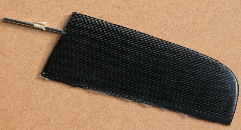
A new 'aha' moment came, almost accidentaly - like most innovations, when Olof tried moulding the rudder core in the same mould as the rudder itself. So the whole of the ruddermould is first filled with epoxy-microballoons and when that has cured the core can be taken out and lightly sanded. That will ofcourse leave very little extra room for the carbon skins - but on the rudder these are only one layer of 200g/m2 carbon which is not going to be very thick. When the skins are laid up and the core inserted I understand there was a bit of compression and fiddling to get the mould to close correctly, but eventually it did.
The final rudder is only a few tenths of a mm thicker than a rudder made the old-style way, but we see big improvements in the surface finish and stiffness. The new rudder also has a very solid overall feeling. A rudder made this way is not among the lightest, but at least it's very strong. The picture below doesn't do justice to the surface quality, it's close to what you can expect from Sails ETC !
So, we will definitely have to experiment with a closer fitting core and more compression on the fin also. Since the skins on the fin are about three times as thick as on the rudder I don't think making the core in the finmould will work, but manufacturing a cnc cut core-mould for the fin should not be a problem once the cnc-mill is upgraded.
Radio installation
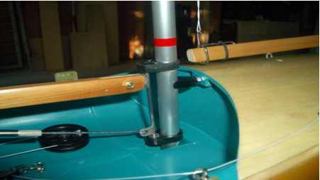
I was impressed with the radio installation and deck configuration I saw on Craig Smith's new Obsession in Mooloolaba:
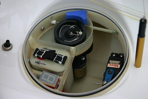
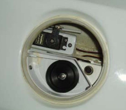
The boat has only one circular hatch, the rim and lid taken from a Decor food-container, and all the radio gear are installed through this hatch. No more deck-patches. Ever !
Craig has made a custom moulding that fits the rim of the hatch and attached the RMG winch, his no-leads battery pack, and the Rx + a flash display to it. The servo is mounted to a plate that hangs from the deck, attached just to either side of the sheeting post.
Gary Cameron has also adopted a similar layout on his TS3:
The winch and the servo are clearly visible, but as I have not seen this boat in person I don't know where the battery and Rx are.
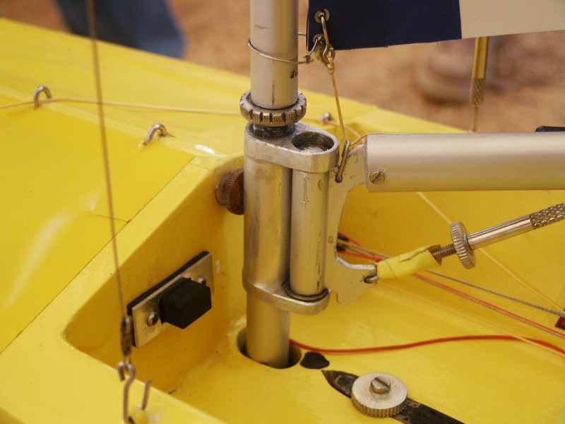
I'm going to use the RMG winch, but Olof prefers the smaller and lighter Graupner Regatta winch, so our system should allow both options. The latest idea looks something like this:
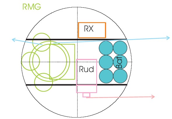
The thick black lines are vertically mounted sheets of rigid glassfiber (PCB board is a convenient supply). They form a 'pot' for the battery to sit in, there's a cutout in one of the sides which allows mounting the rudderservo (pink) vertically, and a horizontal PCB piece which forms the mounting plate for the RMGÂ is glued in-between the lengthwise boards.
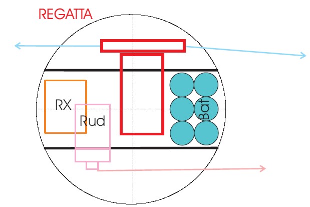
In the Regatta configuration the which is mounted similarly to the servo in a vertical position with the drum to one side and the rudder arm to the other. Note that the regatta uses a significantly larger drum than the RMG.
In both cases the sheeting system will look similar to the one Craig uses on his Obsession:
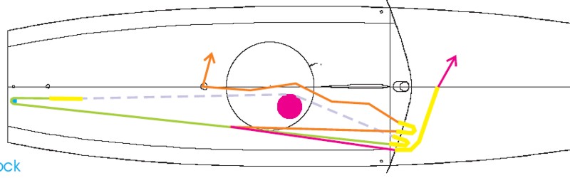
An endless loop starts at the winch (dashed line), goes aftwards through some plastic tubes and comes out on deck through another plastic tube (yellow). The line (green) then continues aft to a block at the transom(blue) and dives below deck again somewhere around the bulkhead (U-shaped yellow tube) to come back to the drum. The mainsheet (orange) needs a block or a loop to pass through somewhere around the bulkhead before it is continues to the sheeting point. Similarly, the jibsheet is routed forwards to a suitable sheeting point for the jib. On my current boat I've sometimes had problems with the jibsheet hooking around the wire-loops that guide it or around the winch, the gooseneck, or the mast partners - That's why I'm considering having the jibsheet in an internal tube (yellow) that starts at cockpit deck level and comes out at the sheeting point on foredeck. Should eliminate the hooking/snagging problems.
For the radio, I've been happy with the DSM system on my Futaba 3VCS, so the new boats will probably be equipped with the Spektrum DX6.
Fittings
First our goal was to get the new boats ready this year (the season ends in November at the latest in Finland), but now it seems that due to various delays that is not going to happen. So there's lots of time during the winter to design and manufacture any custom fittings we can come up with.
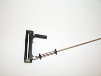
A ball-raced gooseneck/mainboom fitting was the first thing we thought about. Here are a couple desings I've found on the web:
Peter Trimmers homemade FAT-Noux:
The ball-raced fitting sould by www.rcsegel.de:
A heavily modified Sails ETC fitting on an Australian boat at the Vancouver Worlds:
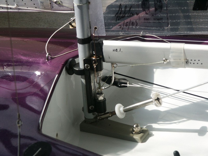
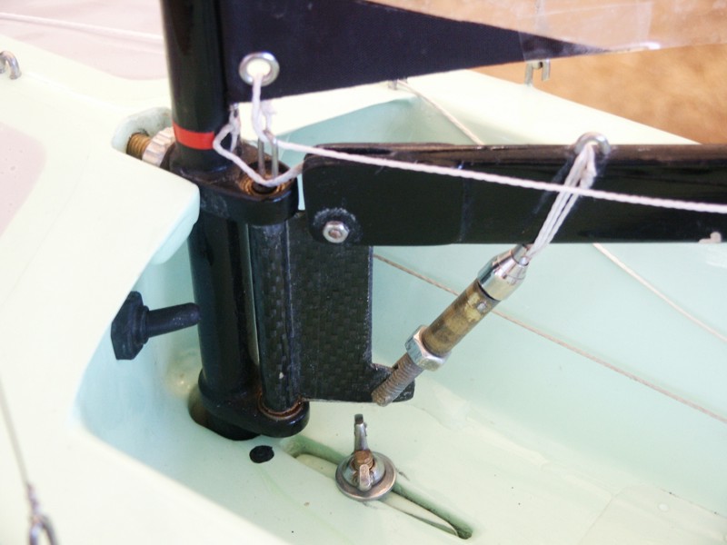
Michael Scharmers boom fitting at the Arcos event:
Another M Scharmer boat:
Â
I've found a good source for miniature ball bearings in the UK: www.smbbearings.com, quick responses to emails, order by fax+visa card, and about three days delivery to Finland - excellent !
The only small minus for smbbearings is that they do not have their prices online. Expect to pay around 3 to 5 eur per bearing for the stainless steel versions.
Â
To be continued...
I was wondering if I took the line drawing and used wider material to make a male mould, I would get a wider boat. Will this work.
Hi Andrew,
I think that it more or less exactly what Peter Trimmer did, he sent me some photos and text about his project and they are at
http://www.anderswallin.net/2006/03/building-a-wooden-noux/
and
http://www.anderswallin.net/2006/03/an-aussie-fat-noux/
A few mm of extra thickness will probably not affect performance very much. The boat will float a little higher than the design waterline, but as soon as you get up to speed or there are waves the waterline should be as long as on any boat.
If you don't want a bigger boat, offsetting the hull lines to accomodate for the skin thickness in your plug or hull is quite easy in most CAD programs.
Anders
Anders thank you for the responce, I do not plan on using shadow, I plan on using MDF (wedium density fiber board) to make a mail mould. instead of using 5mm thick board I will use 10mm and then taper in the middle (center line) back to 5mm. then i will plane it sand it and there is my male mould? If i print off the Noux side profile then enlarge it with photo copier or is there a place to get full size drawings? I have another Question. I have an old windsurfing fin that is long enough for an IOM fin, but it has a bit of a curve to it front to back? Would this work, very stiff. I do not plan on racing just having fun. I built a triple crown already an just like to make things wil as little cost by using what I have lying around the shop.
from your description I'm not sure how you are going to build the plug... recently we have had the opportunitu to CNC mill our moulds from MDF. That is a very nice way to do the plug if you can find a machine near you and someone who will do it for a reasonable cost.
The MDF surface will need to be sealed and polished before making a mould. We've not invented anything that would make this an easy and quick process. 2-component epoxy or polyurethane paints seem to work best but it is still a process of repeated painting and sanding + polishing.
If you take the DXF file to a professional printer it should be possible to order full size plans. Make sure you agree to pay for the plans only if they are the correct scale ! (there should be plenty of measurements in mm indicated on the plan). At work they charge about 30euros for full color A0 poster prints - grayscale plotting might be cheaper ?
The fin we use on the Noux is a 6% thickness/chord NACA fin with an 85mm chord. The thickness is thus 85*0,06 = 5,1 mm. Anything much thicker than that will carry a performance penalty. If your surfboard fin is of similar size then it could work. If it has a lot of curvature that will move the lateral center and you need to adjust the position of either the fin or the rig. Only way to find out if it works is really to test...
Anders, I have seen when people take the side profiles then glue them to mdf, then use a planer to take down the high spots, then they get the rough shape then sand from there. Winters are long here so I have to try somthing. Then I plan on using the German rubber process I have found on other site. They use latex rubber pulled tight over mould then repeat after glass and resin applied.
Hi Anders,
I like the design of the noux and would like to build one too. In your first answer you (more or less) said it's quite easy to reduce the size of the shadows for a planked hull. Can you tell how I should do this (preferably by using some freeware software). I am planning to buid the hull using 3 or 4 mm balsa planks, so I think I need shadows reduced by 2 or 3 millimeters.
regards,
Eric
Hi Anders,
Nice information about radio installations.
I like the easy access on Craig's boat with the wide decor hatch. Any idea of the availability of the wire free battery and its socket? Is it similar to the Lithium batteries in digital cameras?
I have bought Gary Cameron's TS3 and can tell you that he had the battery attached by velcro to the fin box and the receiver by velcro under the deck. Both are difficult for me with injured fingers, especially when cold. I have the receiver velcroed to the hatch and the battery lies in the bottom with a cord to stop it sliding forward. The only problems are the battery can get wet (sea water kills cheaply made NiMH interconnects instantly) and the hatch is too small for my clumsy hands (the battery only just passes and the winch is a really tight fit when I have to clean the exposed gears).
I am undecided on whether a lid is better than sticky patches. Anyone else able to comment?
Incidentally I use the Spektrum 3 channel system on a Hitec Pro Car transmitter for small courses but have to change to an FM system for large courses to get the range without losing the boat at crowded distant buoys. Ive not tried the receiver antenna mods yet.
thanks for the site
Jerry
Hi Jerry,
Thanks for the info about the TS3 radio installation.
I'm not going to sit anything on the bottom of the boat - too much risk of water damaging radio/batteries, just as you mention!
The lid I am using, and Craig has on the Obsession, is bigger than the TS3 lid I think. The inside diameter is about 115mm and the outside diam. is 130mm for the recess I am making.
Having sailed with sticky patches on many boats I'm looking forward to the hatch. As long as it is watertight and works as it should it will be much lower maintenance than sticky patches. The boat is a lot harder to build with the hatch for sure, but I think it's worth it.
Spektrum range: I've found the addon module to the Futaba 3VCS gives enough range if the Rx antenna is mounted correclty and you remember to keep the Tx antenna vertical. For the new boat I'll be using a DX6. The output power of the DX6 was supposedly reduced before it came on the European market (all radio products need to be 'CE'-marked), so we'll have to wait and see what range I'll achieve.
Anders
Eric,
I'll try to make some reduced shadows of the Noux when I have time, hopefully within a few days. If it doesn't happen, keep reminding me ! 🙂
Hi again Eric,
there's now a plan with reduced shadows at
http://www.anderswallin.net/2006/10/noux-reduced-shadows/
Anders
Hi Anders, re my recent comment regarding the waterproof aspect of Round/Square Deco containers, I should have mentioned, (more important than the "look", which of course is subjective anyhow), is the extra room it gives you.
Mine is just a cover that still avoids using "sticky back" but gives (lots of) access to the hull, & the battery & RX are mounted in appropriate positions in the hull.
As stated previously a bit of vasoline on the square cover has my boat bone dry even in the roughest conditions.
John,
Thanks for your comments.
If you have a picture of your hatch setup I can publish it here.
Anders
Anders,
Thanks for the pictures of sevearl vang solutions. In your opinion, what is the shortest practical distance between the bottom of the boom and the vang fitting below? The reason for asking this question is that the standard Sailsetc ball raced vang/gooseneck fitting is about 70 mm from the top of the fitting to the bottom of the vang fitting. I have heard of people getting that distance down to about 60 mm, but if one makes a custom fitting, what do you figure the practical/useful minimum distance may be?
Thank you.
Hi Brig,
Strength-wise I would think that a lot less than 60mm would be enough. The kicking strap is more problematic.
Once there was an explicit rule that said that the kicking strap must act only in tension and must act from below the boom. I think the current understanding of the IOM class rule is that this idea still holds. The kicking strap is defined as rigging, and rigging is something that acts in tension.
So as you reduce the height of the boom fitting the kicking strap will act more along the boom. That makes the kicking strap very sensitive, i.e. one turn on the screw will move the boom much more than previously. One solution shown above on Michael Scharmer's boat (light green boat with black carbon fitting) is to tilt the screw more upright. Another solution would be to have some kind of gearing on the kicking strap where one turn of the screw is geared down to move the boom less.
SailsETC has a fitting with this gearing idea which is meant for a big boat (A-class or similar), item 14B:
Anders
Hi Anders,
I have finished planking a Noux hull and the time has come to fit the fin box. Is the best location for front of fin still best positioned at 515mm from the bow, and the centre of mast 495mm from the bow. Just wanting confirmation from your testing before making the first hole. I can also send some pics if you let me know how.
thanks
Brett
Hi Anders,
In the answer to my question about fin measurement and positioning, you referred to the NOUX project dated 2002. But I’m building the Noux hull starting from the new layout plan dated march 8th 2006 and the positioning of the fin and mast are different from the layout of the 2002 plan. Please could you give me a suggestion about the correct positioning to adopt.
Tank you
Ciao
Luciano from Italy