Tag: cutsim
Mowing Foam
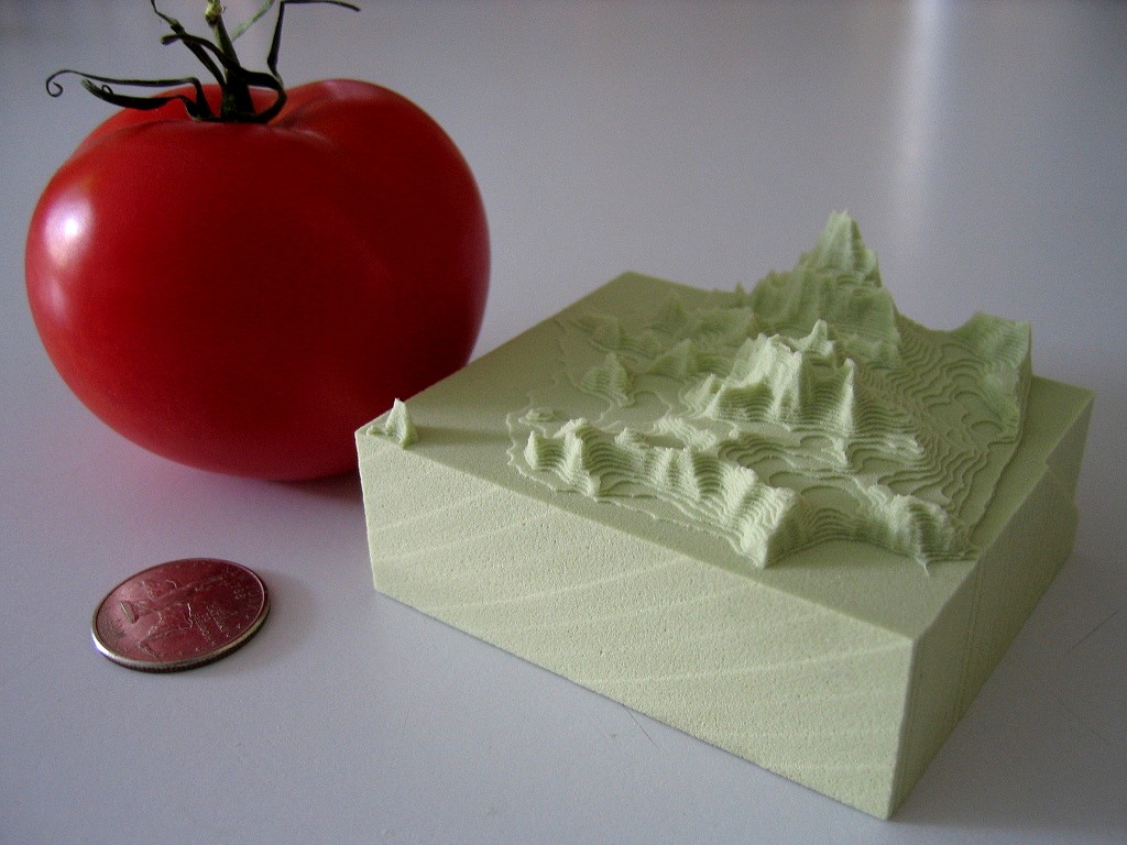
Dan Egnor sent me this nice example of bitmap-based toolpath generation, or 'pixel mowing'. It's a slightly exaggerated topographic relief of San Francisco machined in tooling board using a very simple 'lawn mowing' toolpath generator.
The explanation of how it works below is mostly Dan's, not mine.
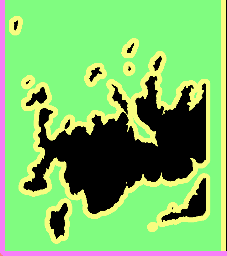
This is the input to the toolpath generator for one of the Z-slices.
black - material which must not be touched
green - to be removed, is safe (at least one tool radius from black)
yellow - remove if possible, is dangerous (within tool radius of black)
purple - has been cleared, is dangerous (machine limits or similar)
white - has been cleared, is safe, is not blue (below)
blue - this spot has been cleared, and is safe, but is within one tool radius of material that needs clearing (green or yellow)
Note that you don't see blue in either "before" or "after" images, it only occurs transiently. (In theory it could show up in "before" as area outside the workpiece.)
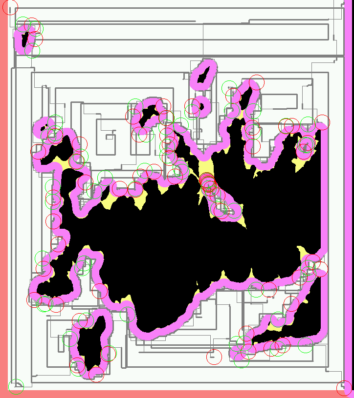
And this is the resulting toolpath. Green circles are plunges and red circles are lifts. The thick grey lines represent actual cuts, the thinner lines are rapid feeds.
The basic rule is that the tool *centroid* is only allowed to visit safe areas (green, blue, and white). Green and blue represent work to be done (safe areas that need visiting). Of course, as the tool moves, green changes to blue and white, and (some) yellow changes to purple.
The real trick is in efficiently tracking the "within tool radius of" zones (material to be cut, or material to stay away from). Every pixel keeps a count of how many pixels of each type ("nearby-blocking" or "nearby-cutting") are within one tool radius of that pixel. Whenever a value is changed ( e.g. the simulated tool moves and changes some points from "cut" to "clear"), every counter within the appropriate radius is updated.
That would be rather costly to implement directly, each simulated pixel move would require N^3 updates, if N is the diameter of the tool. Instead those counters are only kept as *differences* between each point and its neighbours. That means changing a point only requires updating the values along the *perimeter* of the radius surrounding that point, meaning that a simulated pixel move only requires N^2 updates, which makes things a lot more tractable (though it still takes the old laptop I use a couple minutes to complete the toolpaths for a 5" x 3" x 1.5" model at 1/256" resolution). Of course this means that the "color state" isn't directly accessible for a random pixel, but must be figured incrementally from neighboring values. Fortunately most operations don't access random pixels.
You would probably not want to cut metal with this kind of algorithm as there is no control over material removal rate or cutting forces, but for foam, tooling-board, or wood it should work ok.
Dan's program is written in C++ and available here (http://svn.ofb.net/svn/egnor/boring/), but it's not well documented.
We are standing by for a video of this kind of cutting!
Mowing tactics
Moving forward with the CAM coding, the sensible thing would probably be to work on mundane things like 2D offset generation, a kd-tree for faster drop-cutter searches, and zigzag-paths from 2D outlines... There's again been some talk about open-source CAM on cnczone, but not much in terms of results or actual descriptions or implementations of toolpath algorithms.
Anyway, here's something more fun than the traditional computational geometry problems I referred to above. It's lawn-mowing tactics, or how do you program the circular robot to mow the red pixels while not cutting too many of them at a time. This is a slightly improved version of my earlier trial. This one considers a number of angles in all directions for each move. From these moves the ones that cut away a suitable amount of material are selected. Additionally I've introduced a cost function for changing direction, it should be easier for the cutter to continue traveling in approximately the same direction than to do abrupt turns. In spite of this, about half-way through the cutter reverses direction...This is obviously done with a bitmap representing the grass to be mowed, but I wonder if it would be better to try to do it more exactly: represent the boundaries of the grass with lines and arcs. A variable step-length also seems like a good idea, on long straight bits the cutter should be able to move in one go as far as it goes.
An emergent spiral
Most conventional CAM algorithms are geometry-based. They create toolpaths that are usually parallel to either the coordinate axes ('zigzag'-paths) or to the part contour (contour-parallel, or spiral paths). One problem with this geometry-based stuff is that you don't take into account the cutting forces. The algorithm has no idea about how much material is removed while the tool is moving. A quick patch is to run a cutting simulation after the path is created and adapt the feedrate for constant material removal rate (MRR).
Another option is to base the toolpath algorithm on a stock model. Then you know the shape of the stock at all times and you can control the MRR or cutter engagement angle. To quickly test how this could work I made a small test in matlab.
The cutter (green circle) is moved around by some rules, and cut's the red pixels as it travels over them. Cut pixels are drawn in blue. The cutter is moved around in discrete steps in some direction, and you're only allowed to cut a certain number of pixels per move. The tricky part is coming up with the rules for our 'lawn-mower' robot. Now I'm using a simple idea: If the past move was made at an angle alfa, try to take the next step in the same direction, but if that's not possible increase alfa until the MRR goes down to some preset value.
This idea will need refinement so that the robot can cope with walls, can do cutting in only one direction (climb vs. conventional) etc. etc., but this seems like a promising and fun start!