X-axis progress

Now that we have the new spindle on our mill, and the linear rail+ballscrew conversion for the Z-axis have been working for a while, it's time to upgrade the X and Y axes.

Jari has made some good progress on the table/X-axis. The IKO 15 mm linear rails are mounted, we've machined and attached the bearing holders for the ballscrew, made a motor mount for the servo, and also worked on the steel saddle plates. The new talbe is much bigger than the old one, and will allow about 500mm of X-axis movement. That's going to be enough to machine fin and bulb moulds for an IOM in one go - something that we can't do right now.

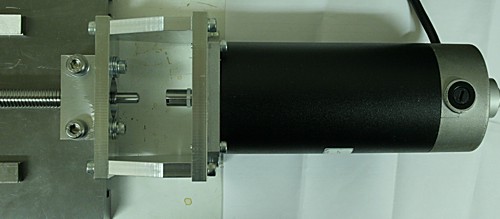
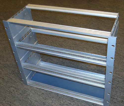
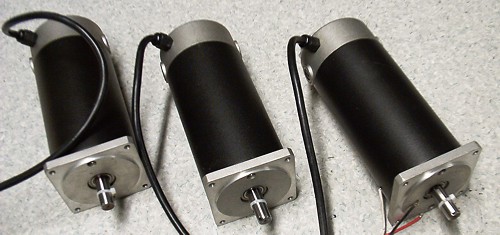
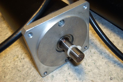
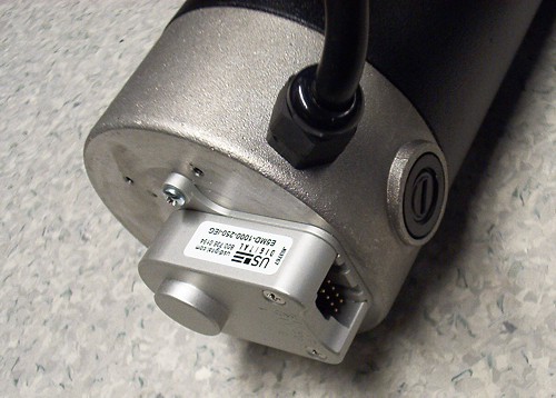
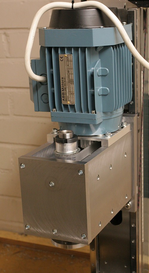
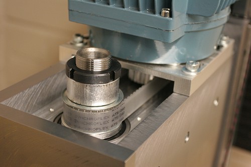
Here's a close-up of the motor mount, all parts machined from aluminium using our own mill. There's room for a coupler between the 12mm motor shaft and the 8mm ballscrew end. The motors we are using are 1.6 Nm continuous torque DC brush motors from Camtronics. Keeping to the KISS principle, we are hoping the motors are strong enough to work in direct-drive (no belt reduction or gears).

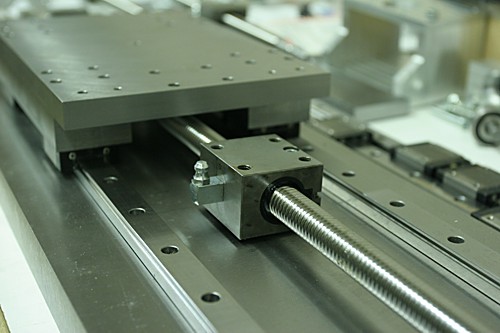
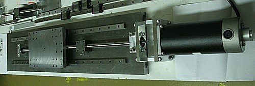
This photo shows the ballscrew (16mm diameter, 2.5mm pitch, from metallstore.de), the ball-nut, and the X-saddle plate with some steel bars under it to make room for the ballnut. Next up is a similar assembly for the Y-axis. That's going to be a bit more complicated since the parts will eventually have to be mounted on the very mill we are making them with! Hopefully not too many iterations of disassembly/assembly will be required...

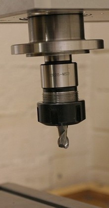
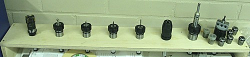
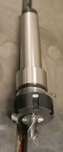
Jari has also made a new tool-holder:

Offset Ellipse

Continuing with some random thoughts on CAM algorithms, here's a diagram I drew in response to a question on offset ellipses posed by Julian Todd.

(click image for high-resolution version)
The task is to find an offset ellipse to a given ellipse (magenta). The offset ellipse (blue) should lie a distance T, measured along the normal to the ellipse (I've drawn one normal of length T in green), from the original ellipse. Drawing the offset ellipse is simple, but it's a bit harder to find a point on the offset for a given x-coordinate x=k. I've marked this point with a circle, and its coordinates are (k, E(k)), so E(k) is a function that returns the sought y-coordinate.

I took Julian's advice of using a numerical method with respect to the geometry (not neccessarily cartesian coordinates), and parametrized the ellipse as a function of an angle t. So points along the ellipse lie at:

ex=a*cos(t)
ey=b*sin(t)

Where a and b are the major and minor axes of the ellipse, and t is an angle between 0 and 2pi. At every point there's a normal vector

nx = b*cos(t)
ny = a*sin(t)

To find points on the sought offset ellipse, we need to scale this normal so it's length is T. Each normal has a length

l=sqrt(nx^2 + ny^2)

So the sought normal vector is

nx_T = (nx/l)*T
ny_T = (ny/l)*T

or more explicitly

nx_T = ( b*cos(t) / sqrt((b*cos(t) )^2 + (a*sin(t))^2) ) * T
ny_T = ( a*sin(t) / sqrt((b*cos(t) )^2 + (a*sin(t))^2) ) * T

Now, points on the offset ellipse lie at

oe_x = ex + nx_T
oe_y = ey + ny_T

and we need to find the particular t angle which results in a point (oe_x, oe_y) for which oe_x = k holds. Inserting the above expressions, this happens when:

(a+T*b/sqrt( ( b*cost(t) )^2 + ( a*sin(t) )^2 ))*cos(t) -k = 0

I haven't looked for an analytic solution to this equation, but plotting it for a few test cases seems to indicate that it's fairly 'benign', and Matlab's fzero function finds a solution very quickly. If we call the solution to this equation tk, the sought point on the offset ellipse is

E(k) = oe_y(tk)

Here are two Matlab scripts I used to plot this figure: ellipsetest.m is the main program, and oe.m is used when solving the equation.

Defining a milling cutter

Some discussion over at the freesteel blog about defining a general purpose milling cutter shape in a CAM program.

I made this diagram (which hereby is in the public domain) to make it all clear in my head:

(click image for svg file)

It shows one half of the cross-section of the cutter (the axis of rotation is at the right edge of the image). There's a cylindrical part of height ha with radius a, a conical part of height hc that tapers down to radius c, and finally toroidal part of height hf.

The idea is that by writing all CAM algorithms to deal with this tool shape, nothing has to be changed when locating cylindrical, conical, ball-end, or bullnose cutters against the model. All these cutter shapes are different variants of this general shape.

A general purpose CAM program would test this cutter shape against a triangulated model. There are four surfaces on the tool, s1, s2, s3, and s4. These all need to be tested agains the model. There are also three edges (e1, e2, and e3), but only e1 needs to be separately checked against the model since if e2 or e3 were touching the model, so would the adjecent surface.

Enclosure for servo electronics

I've bought three 19" rack enclosures from fellow cnc-enthusiast Jiri K:

My plan is to house the PSU, based on a 230 VAC to 2x30 VAC 1.8 kVA transformer, in the bottom box (I might have to extend the encolsure a little, the transformer should the same as Sauli J:s transformers, about 220x220x120mm). The middle box will have the servo amplifiers, and the top box will contain the optoisolators and some low-voltage logic. The top box connects to the m5i20 card in the computer via three 50-pin ribbon cables.

Together with Jari we made some panels for the servo box (bottom), and the logic box (top). The servo amps connect to the motors through the round black 7-pin connectors. Each pin is rated for 7.5 A, so I might use two pins per pole just to be safe. The logic box has six D25 connectors: four for encoders (X, Y, Z, and Spindle), one for the jog pendant, and one for limit switches (we'll have to make a separate Y-cable or something for those). There's an E-stop switch to the right, and a connector+switch for AC mains.

Here I've mounted three PWM servo amplifiers and one PWM switch from pico-systems to the back of the servo box. Secured to the back rails of the box by four M3 screws to the heatsink. The 120x120 mm fan is probably a bit overkill - but overkill is fine when it comes to cooling. At the top you see the back of the motor connectors.

More pyVCP Widgets

Since last Monday, I've been adding to the range of available pyVCP widgets:

Spinbox:

Jeff Epler suggested that my initial 'jognumber' would be better implemented with a Tkinter spinbox. It sets the value of a FLOAT by either pressing the up and down arrows, or using the mouse-wheel.

Radiobutton:

This widget creates a number of BIT pins and sets only one of them, corresponding to the checked box, true.

Jogwheel:

This resembles a real jog-wheel, and outputs a FLOAT count corresponding to the position of the wheel. The wheel rotates either by dragging with the mouse, or by rolling with the mouse-wheel. The number of counts is adjustable, 50 cpr shown in the pic I think. This will be useful for debugging jogwheel code to be used with real jogwheels, but could also find other use in pyvcp panels.

Meter:

A traditional dial-indicator, used for displaying a FLOAT. The start and end values are user-configurable.

Extending AXIS with pyVCP

Maybe the most popular GUI for EMC is called AXIS. It shows a number of useful buttons, the 3D view, G-code file view etc. But depending on machine configuration and hardware, users might want to display different things on the screen and have customized controls. There's been some previous work on virtual control panels, or VCP. That was done in C using GTK widgets which I am not at all familiar with... I really want this kind of control panel for the new mill setup, so I've put together two Python programs that create Tkinter widgets that are connected to HAL pins. I call it pyVCP (Python Virtual Control Panel). Here's the first test from yesterday:


The uppermost widget is a slider that controls a HAL_FLOAT. Next is a button which sets a HAL_BIT true when pressed. The small rectangle is a checkbutton, which stays down when pressed, also for controlling a HAL_BIT. The status of a bit can be shown with a LED (red circle). HAL_FLOAT values can be indicated either by bars (green), or as a number.

To enable users to individually configure their extra bells and whistles it makes sense to have a text file that describes the panel setup. The easiest way I found to read and write structured data in Python was XML. Here I've used a number of the different widgets and ways to pack them to demonstrate what's possible:

Finally the best part. Since AXIS is also written in Python/Tkinter, AXIS author Jeff Epler was quickly able to integrate my work with the current AXIS, so you can have your custom control panel right next to the familiar view:

There's a bit more (including source files) in the EMC Wiki, and the latest versions are committed to CVS.

DC Servos for CNC mill

In trying to keep with the KISS principle, I've decided that the AC servos are much too complicated and fancy for our CNC mill. I picked up these DC servos from the post today. They are 90 VDC servos with 1000-line encoders. I got them from Dan Mauch/Camtronics.

To further keep things simple, the idea is to directly couple the motor to a 2.5mm/rev rise ballscrew (HiWin, from metallstore.de).

This will give plenty of feedrate, the motors are rated at max 3000rpm which corresponds to 7500mm/min. I doubt we will need that much ! The lower end might be problematic, since motion could get jerky when there are not enough encoder counts coming in...

The motors are rated for 1.6 Nm of continuous torque. The maximum push force can be estimated using

F=2*pi*T*eff/L

where F is the force (N), T torque (Nm), eff efficiency (I've asumed 80%), and L the ballscrew lead. If I plug in these numbers I get a bit over 3000 N which should be enough.

Here is the US Digital 1000-line encoder. When counting each edge, we get 4x1000= 4000 edges per revolution, or 0.000625mm of movement for each count. We're aiming for about 0.01mm accuracy on final parts, which means the motion control needs to keep within a 16 count window (or +/- 8 counts) of the commanded position at all times.
The motors will be driven by PWM Servo Amplifiers from Jon Elson/Pico-systems. The PWM signal for the amps is generated by the M5i20 motion control card from Mesa Electronics. All of this is ofcourse controlled by EMC.

AC Servo Motors for Sale

I haven't magaged to find economical servo amplifiers for the AC servos I bought about a year ago. I'm now planning on using DC servos instead since amplifiers for them are more commonly available, which meanst that the AC servos are for sale. I've put them up on ebay:

one 1 kW Sanyo Denki P5 100VAC  brushless AC servo.

three 400 W Sanyo Denki P5 100VAC brushless AC servos.

Happy bidding !

New Spindle Installed

The new spindle for our cnc mill has now been installed. The aluminium plates holding the bearings are now supported by steel plates on all four sides. A bracket for holding the motor has been made, with elongated mounting holes for tensioning the belt. We're now using the Z-axis with linear rails and a ballscew, the conversion for the X- and Y-axes is still work in progress..

The spindle from below. We see the aluminium plate holding the lower bearing. We still need to fit a guard plate which protects the bearing from chips, coolant etc.

A major improvement over the old spindle is that the new spindle is belt driven instead of the gears we had on the old one. This reduces noise a lot, which makes running the machine for longer periods of time much more pleasant. The belt is a 1:1 ratio AT5 standard belt. The 750 W ABB induction motor we are using now does about 3000rpm, so for small tools (6mm or so) we are still lacking a bit in spindle rpm. The plan is to replace this motor with a 1 kW servo which will do 4500 rpm maximum, and could also be geared 1:2 since it will be driven by a closed-loop system and we can monitor the load on the motor.
 

The spindle has an MT3 taper, and we're now using ER25 collet toolholders which hopefully will mean that we can input the tool length into EMC and not have to re-set the Z coordinate zero on every toolchange.

Preliminary tests show that the finish on milled surfaces has improved a lot with the new spindle. Face-milling now produces an almost 'mirror' finish, and milling with the side of an end-mill now produces acceptable surface quality when previously the finish was quite horrible... The real acid-test for our machine will come when we get the linear rails and ballscres installed for X and Y, and also convert the whole control to AC servos - then we should have a machine that can produce good quality parts at a reasonable rate.