Point in triangle test

The facet test I wrote about yesterday needs a 'point in triangle' test to determine if the found CC point lies within the given triangle and we should thus care about the ze value the algorithm determined, or if the CC point is outside, and we can skip to the next test/triangle.

I wrote a function isright(p1,p2,p) which tells me whether the point p is right or left of the line from p1 to p2. The triangle test isinside(p1,p2,p3,p) uses this function three times:
t1 = isright(p1,p2,p);
t2 = isright(p3,p1,p);
t3 = isright(p2,p3,p);

and if t1, t2, t3 all have the same sign then p is inside the triangle.

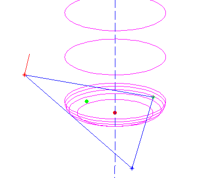
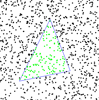
If I add this function to the facet test, I can determine which of the CC points in the plane containing the triangle are within the triangle:


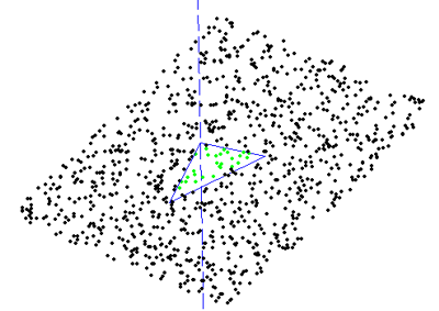
here the dashed line indicates the z-axis.

I'm a little concerned that this works with the projection of the triangle onto the xy-plane. But maybe that isn't a problem because triangles with horizontal normals are special cases anyway. I also haven't yet looked at the rounding/on-edge problems Julian talks about.

I wish the third and final part of this story, the edge-test, was as simple as the vertex and facet tests! At least so far I haven't found a really simple algorithm for the edge-test in the literature (I'm reading Hwang1998 and Chuang2002). Anyone know more about this? please comment below!

Drop Cutter part 2/3: Cutter vs. Facet

Now the problem of contacting a toroidal cutter with the facet of a triangle.

We need to find the equation of the plane which contains the triangle. If the triangle is defined by three points p1 = (x1, y1, z1), p2 = (x2, y2, z2), p3 = (x3, y3, z3) then a surface normal will be perpendicular to both p1-p2 and p1-p3:
N =
(NX, NY, NZ) = (p1-p3)x(p1-p2)
and it can be normalized to unit length by setting
n
= (nx, ny, nz) = N / sqrt(NX^2 + NY^2 + NZ^2)
I've drawn a surface normal in red in the picture above.

Now the plane containing the triangle is given by
a x + b y + c z + d = 0
where (a, b, c) = (nx, ny, nz) and d can be found by noting that any of the points p1, p2, or p3 must satisfy the equation:
d = - nx*x1 -ny*y1 -nz*z1
the plane is going to make an angle theta with any vertical line, where theta = asin(c)

Then we need a new figure:

We start out at ei = (xe, ye, zi) , the point on the plane that intersects the line along which we're dropping the cutter (green dot above). It needs to satisfy the equation for the plane, so
zi = - (d + a xe + b ye) / c
Note: c=0 is a special case which needs to be handled separately.
from here we need to climb up to the correct ze, and that's done by first summing the green distance, then the red one, and then dropping down by r:
ze = - (d + a xe + b ye) / c + (R-r)/tan(theta) + r/sin(theta) - r

Now we have the cutter in contact with the plane, but we still need to check that the cutter contact point (CC-point, the blue dot above) is within the triangle facet and not some other point on the plane. To do that we need (x,y,z): If we start at the red point e = (xe, ye, ze) we get to he CC point by travelling upwards to the yellow point, and then along the normal down to the CC point:

CC = e + ( (R-r)*tan(theta)+r )k - ( (R-r)/cos(theta) +r )n

where k=(0, 0, 1) is a unit vector along the positive z-axis.

All of this seems to work as evidenced by the top picture where a toroidal cutter is brought into contact with a facet. The CC point is indicated with a green dot, and the CL (cutter location, or (xe, ye, ze)) point with a red dot.

Now we need to check if the CC point lies within the triangle, but that will have to wait until the next post... (Mr. Todd has some thoughts on this)

Drop Cutter part 1/3: Cutter vs. Vertex

Based on a 2002 paper by Chuang et al., I'm trying to understand the math for calculating 'drop-cutter' toolpaths (Julian Todd also has a lot to say about the drop-cutter approach). The basic idea is that the x,y position of the cutter is known, and it is dropped down along the z-axis until it touches a triangulated surface. A complex surface is built up of many many small triangles, but the algorithm stays the same.

For each triangle there are seven items the cutter might be touching: three vertices, three edges, and one facet (the triangle surface). It looks like a contact point with a vertex is the easiest to calculate, so I'm starting with that. I'm hoping to post part 2/3 and 3/3 of this post soon. They will deal with the facet and the edges.

I'm using this fairly simple cutter definition C(R,r) where R denotes the shaft diameter and r the corner radius. The three basic shapes that can be defined this way are shown in the picture. A more elaborate model would include tapered cutters, but I think I won't bother with that now... A cutter thus consists of a cylindrical part or a toroidal part, or both. That means I need six different functions in total for this algorithm:

  1. Cylinder against vertex
  2. Toroid against vertex
  3. Cylinder against facet
  4. Toroid against facet
  5. Cylinder against edge
  6. Toroid against edge

Here's how I think no 1 and 2 work.

Assume the vertex we are testing against is at (x, y, z) and say the cutter is at location xe,ye. We are looking for the cutter z-coordinate ze so at the end when the cutter is in contact with the vertex it will be located at (xe, ye, ze) .

Calculate the distance in the xy-plane from (xe, ye) to (x, y):
q = sqrt( (xe-x)^2 + (ye-y)^2)

Now if q > R the vertex lies outside the cutter and we should report an error or just skip to the next triangle/vertex.

If q <= R-r the vertex lies under the cylindrical part of the cutter and we set ze = z

If (R-r) < q <= R the vertex lies under the spherical/toroidal part of the cutter. This picture should explain the geometry:

The cutter can be positioned a distance z1 lower than z. To calculate z1 we need z2. It can be found by noting that (x ,y, z) should lie on the toroidal surface:
(q-(R-r))^2 + h2^2 = r^2
or h2 = sqrt( r^2 - (q-(R-r))^2 )
so now h1=r-h2 and we found ze = z-h1

A quick test in matlab seems to confirm that this works:

here a ball-nose cutter is dropped down along the dashed line into contact with all three vertices (red, blue, and green stars), and finally it's positioned at the highest ze found (red dot).

Well, that was easy. Now onto the facet and edge tests!

Gooseneck prototype

Jari has been developing the ball-raced gooseneck idea. For round booms (and maybe the Sails ETC booms too) there is now a typical 'tang' at the top. Using a rigid compression strut for the kicking strap seems to be questionable under the current rules, so here's a more conventional kicking strap based on a piece of stainless M4 thread, a threaded stainless cylindrical sleeve, and a piece of stainless wire with a 'blob' on the end which keeps it attached to the sleeve. There will be a thumb-wheel on the final version instead of the nut seen above, and probably also fixing-screws for attaching the fitting rigidly to the mast. Jari thinks these fittings could be sold for 60euros each (including all parts and the bearings).

CNC milled rudder mould

As a test-case for our upgraded mill we made this aluminium rudder mould. Surface finish is now significantly better than previously, and this mould will only require light sanding to reach a polished finish. We're still using the stepper motors. Things should further improve a bit with the servos since it will then be possible to run the finish pass with a ball-nose endmill and a very small stepover to reach a nice surface finish.

In the next few weeks when the servos are in use it will be possible to produce fin, rudder, and keel-bulb moulds pretty easily. Moulds for the Noux design will be offered for sale(email me if you are interested!), and if anyone has his or her own design for a fin/rudder/bulb we can very probably produce a mould for that too (limited by the work envelope of the mill, ca 500/200/200 mm X/Y/Z).

First parts with ballscrews/rails

Here are some of the first parts made with our new upgraded mill which now runs with ballscrews and linear rails. Top speeds as well as accelerations are up on all axes, and there's very little risk of losing steps any more. Hope to have the servo electronics ready sometime in May...

Jari also made some useful chip/coolant guards for both the motors and the ballscrews/rails. As you can see these are mandatory when 'making chips' with a 3000rpm spindle and lots of coolant!

The new table is so long it hits the wall - We need to move the machine to a new stand and redo the enclosure.

Servo electronics progress

Now that the mechanical side of our Opti-BF20 upgrade is almost complete I'm trying to get all the bits and pieces together for the electronics upgrade too. Here I've made cables for the servos. Three 1.5mm^2 conductors (+, -, and protective earth) in the black wire carry power to the motor, and I use a 25-pin (10 of which are used) parallel printer-port cable (white) for the differential encoder. Since we're going to be using flood coolant I've used plastic tubes (grey) around the X and Y motor cables to keep them dry.

This is the 'breakout-box' for the m5i20. On the left the jogwheel card is on the bottom with two general purpose IO optoisolator cards on top. To the right the motion-control optoisolator on the botton and the differential encoder interface on top. The next job is to wire everything inside the box and start testing how all signals come through to HAL. I'll put together a pyVCP panel for testing everything.

Opti-BF20 on rails

Jari has almost completed the mechanical part of our cnc-mill upgrade: fitting a new 500 mm X-travel table on linear rails and installing ballscrews.

The bearing holders for the free end of the ballscrews are not done yet, so in the pictures the free ends are ...free. Here you also see how everything is assembled: the Y-axis ballscrew and rails sit on the base of the machine, there's a two-part saddle plate on the Y-bearing blocks, and the X-rails/ballscrew attach to the underside of the table.

The new table assembly is a bit higher than the old table which means that Z-travel is restricted. We also need to make a slot in the Y-axis saddle plate to allow for the axis coupler to slide under it. Now Y-travel is only about 150 mm, but it should go up to 200 with this mod.

Initial tests with the old stepper motors and temporary crude axis couplers are promising. We have elminated backlash, and friction is down a lot meaning higher velocities and accelerations are possible. Can't wait to see how this thing moves with the servos!

Differential Encoder Interface

I threw together this board for decoding the differential encoder signals coming from the servos. I don't like etching two-sided PCBs, but I'm not sure I like this many zero-ohm jumpers either... It's basically four DS3486 ICs with input filters + a lot of connectors.

The circuit is borrowed from an IRF application note, second to last page of this document: http://www.irf.com/technical-info/refdesigns/dg-irmck201.pdf

Not very compact or cute, but hopefully functional...

Source: PADS PowerLogic schematic and PADS PowerPCB PCB-layout.