Dah-Lih EMC2 conversion

Stuart Stevenson wrote about his Dah-Lih EMC2 conversion on the emc-mailinglist, and has allowed me to publish these pictures of his mill. I've scaled the pictures to 1024 pixels wide - click the picture to see it in high-resolution.

Machine after conversion.

Machine before conversion. Pendant has original CRT and buttons.

Control electronics. Jon Elson's PPMC cards at the top.

Relays and transformers.

The new control. The computer is a Gateway Profile 3.

There is a MagicTouch touch screen mounted in front of the computer.

Back side of control. The computer is connected to the PPMC cards by the parallel port only. Jog-wheel and buttons are wired directly to PPMC. The network cable goes to a Linksys WET11 bridge mounted on the back panel.

Drop-Cutter in C#

I've now ported my Matlab work on Drop-Cutter to C#. It can load an ASCII STL file and then run the drop cutter algorithm. Not trying to take too much on in the beginning, here's an example of the output with only two triangles as input 🙂 not quite there yet! (who can spot what's wrong?)

I'll do some nicer demos when I've found the problem. The algorithm runs significantly faster in C# compared to Matlab - and this is without a kd-tree or bucket strategy for finding triangles under the cutter. I've also watched and read some tutorials on threading (threading wrt. to computers, not machining!). This is an algorithm that should scale well on modern multi-core processors (have a few worker-threads running drop-cutter on different regions of the model).

An STL Tux

Together with another Anders (from Sweden) I've worked a little bit on some C# code for rendering stuff in OpenGL. The idea is to put together a basic framework where CAD/CAM ideas and algorithms can be tested. Above one of the first useful screenshots where I've rendered an STL file with about 22k triangles.

The code needs to be cleaned up and made all object-oriented and nice, but after that it should not be hard to test the Drop-Cutter algorithm and generate some raster-finish paths.

I've also been reading a 2004 paper by Yau et al. which explains the drop-cutter algorithm for an APT tool. I'm not very interested in the tapered cutters - but that can be added later if needed. What's more interesting in the paper is a kd-tree approach for finding out which triangles are under the 'shadow' of the cutter.

The idea is that it's not necessary to test against all triangles, only those that are under the cutter. Since the circular cutter and the triangles are differently shaped, Yau et al. start by approximating both cutter and triangles with rectangles. So they generate rectangular bounding boxes around each triangle and also around the cutter. The task then is for a given position of the cutter to find which bounding-boxes(triangles) intersect it. I understand this is a variant of what's called an orthogonal range search in computer science.

If anyone with a good understanding of kd-trees and/or range-searching is willing to help with a C# implementation I'd be glad to send over the Yau et al. pdf!

Drop cutter might work!

Here's the first indication that my drop cutter algorithms(vertex, facet, edge) might work! I'm dropping down a toroidal cutter C(0.5, 0.125) towards a model consisting of a half-sphere sitting on a plane. The CL points are in magenta with cyan lines between them. 382 triangles in total. The code has no optimizations, so at each x,y position we check against all triangles.

Here's another one with about 1800 triangles, and with the points more densely sampled in the Y-direction. (click for slightly higher resolution version)

These still pictures are not nearly as convincing as a moving animation - so I will have to do that next with a more complex model. Stay tuned...

Drop Cutter 3/3: Edge Test

The third and final test in the drop cutter algorithm is to drop the cutter down so it touches an edge. The vertex and facet tests were quite easy, but this one requires a bit of calculations. I'm following Chuang2002.
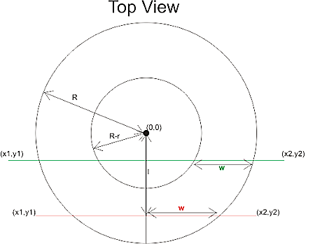
To simplify things we first translate the tool in the (x, y) plane to (0, 0), and then rotate the edge we are testing against so that it lies along the x-axis and is below the cutter (or on top of the x-axis). The distance from the edge to (0, 0) is l.

Now we imagine a vertical plane through the edge and slice the cutter with that plane. There are two cases, depending on l.

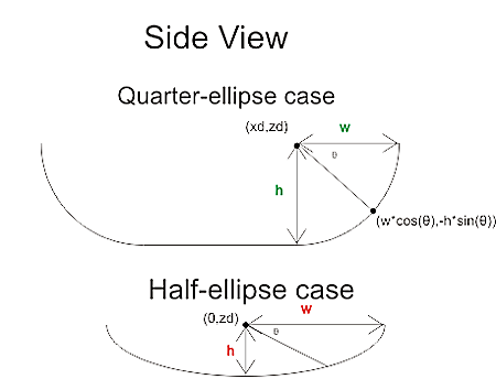
If R-r>l we are cutting with a plane (green) that results in an intersection that has two quarter ellipses at the sides and a flat part in the middle. These ellipses have centers with
xd = +/- sqrt( (R-r)^2 - l^2 )

The other case is shown with a red line: if
R-r<=l<R
the intersection of the cutter will be a half ellipse centered at xd=0.
In both cases the curved part of the intersection is described by
f(theta) = (w*cos(theta) , h*cos(theta) ) where 0<theta<pi
h and w, the height and width of the ellipse are given by

  • quarter-ellipse case:
    • h=r
    • w=sqrt(R^r - l^2) - sqrt( (R-r)^2 - l^2 )
  • half -ellipse case:
    • h=sqrt( r^2 -(l-(R-l))^2 )
    • w=sqrt(R^2-l^2)

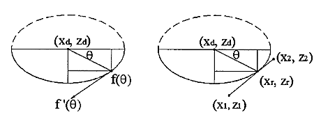
Now that the geometry is clear we can have the edge contact the intersection. That happens at a point where the tangents("slopes") are equal. A tangent vector to the ellipse is given by
f'(theta) = (-w*sin(theta) , -h*cos(theta) )
which can be equated with the slope of the line:
w*sin(theta) / h*cos(theta) = (x1-x2)/(z1-z2)
and we find the angle theta of our CC point:
theta = atan( h*(x1-x2)/w*(z1-z2))
(z1=z2 is a trivial special case not handled here)

The CC point is now given by
xc = xd +/- abs(w*cos(theta))
which should be checked if it lies between x1 and x2. If it does we are contacting the edge, and we can calculate the z-coordinate of the CC point as:
zc = ((xc-x1)/(x2-x1))*(z2-z1) +z1
and finally that leads us to the correct cutter height
ze = zc + abs(h*sin(theta)) - r

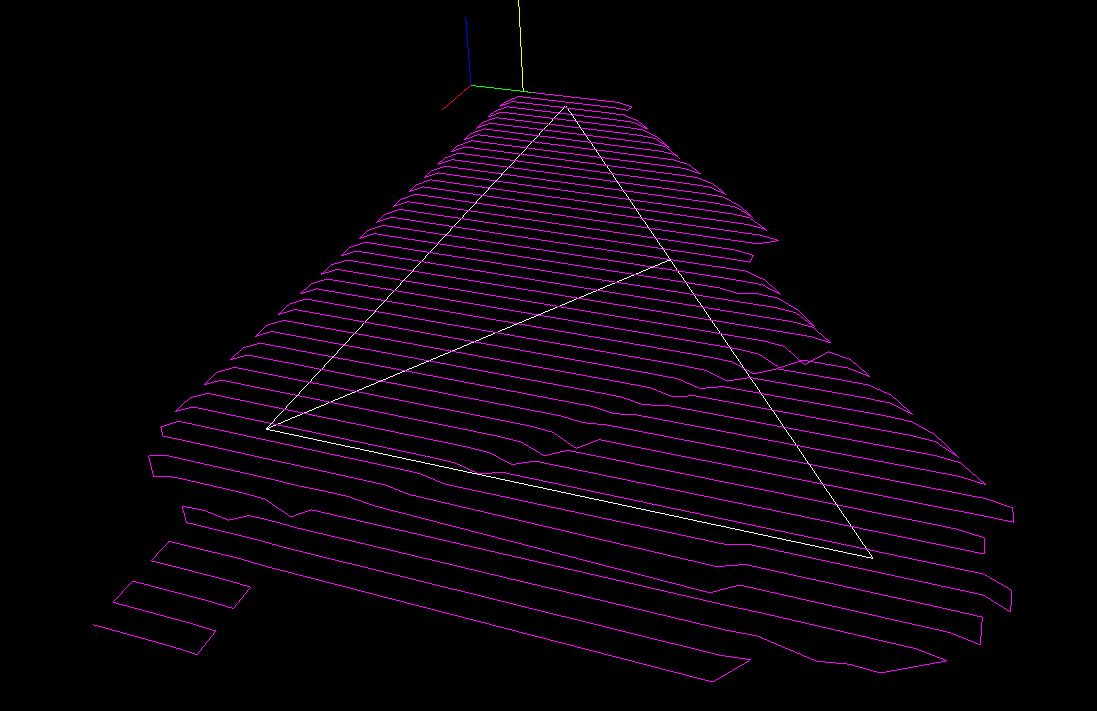
Now I need to put all these tests together and find a way of importing STL files into matlab. That way I can begin to test if/how my drop cutter algorithm works!

There's still a lot to do before I have a set of algorithms for basic 3-axis toolpath creation: "push-cutter" a 2D version of drop cutter, 2D line/arc? offsets, zigzag paths, STL-slice with plane, z-buffer simulation of stock material, to name a few things...

Opti-BF20 in action

Jari has made an enclosure around our cnc-mill, and that allows us to use a liberal amount of flood coolant. Here's a short video with some tests in aluminium.

Before you run to the shop and get an Opti-BF20 of your own please remember that our machine is seriously modified. We put a new table on it with linear guides, we're using ballscrews, and the stock spindle and spindle motor are replaced.

1800 W 80 V PSU for servos

I've put together a simple unregulated power-supply for use with the DC servos that are going on the cnc-mill in the near future. The design is as simple as it gets: 230 VAC input, fuse, 2-pole switch, inrush-current limiter, 1.8 kVA toroidal transformer with twin 30 V secondaries in series, diode bridge, and finally four 10 000 uF electrolytes.

I did a load-test by hooking up various random devices I could find. It didn't exactly go as planned, since most stuff I could find is designed for 230 VAC. I had a resistor rated at 2000 W, a 500 W halogen lamp, a small oven etc. so you would think I could have gotten up to full load? But no, the stuff rated at 230 VAC doesn't dissipate nearly as much energy at 70 VDC 🙁

I was surprised at the largish voltage drop measured, but it's totally unregulated so something like this was to be expected. At about 7 A load I measured a voltage ripple of 1.4 V - which seems OK. A fit to the latter points show an effective series resistance of about 1.9 Ohms for the transformer. I've extrapolated my measurements with dashed lines up to around 1000 W which I estimate is the maximum we will ever use. Hopefully the voltage drop will not be problematic, since overall the system is under closed-loop control.

An emergent spiral

Most conventional CAM algorithms are geometry-based. They create toolpaths that are usually parallel to either the coordinate axes ('zigzag'-paths) or to the part contour (contour-parallel, or spiral paths). One problem with this geometry-based stuff is that you don't take into account the cutting forces. The algorithm has no idea about how much material is removed while the tool is moving. A quick patch is to run a cutting simulation after the path is created and adapt the feedrate for constant material removal rate (MRR).

Another option is to base the toolpath algorithm on a stock model. Then you know the shape of the stock at all times and you can control the MRR or cutter engagement angle. To quickly test how this could work I made a small test in matlab.

The cutter (green circle) is moved around by some rules, and cut's the red pixels as it travels over them. Cut pixels are drawn in blue. The cutter is moved around in discrete steps in some direction, and you're only allowed to cut a certain number of pixels per move. The tricky part is coming up with the rules for our 'lawn-mower' robot. Now I'm using a simple idea: If the past move was made at an angle alfa, try to take the next step in the same direction, but if that's not possible increase alfa until the MRR goes down to some preset value.

This idea will need refinement so that the robot can cope with walls, can do cutting in only one direction (climb vs. conventional) etc. etc., but this seems like a promising and fun start!