30s exposure at ISO400 of the Pleiades. Again some light clouds rolling in around 22:30 preventing further photos...
30s exposure at ISO400 of the Pleiades. Again some light clouds rolling in around 22:30 preventing further photos...
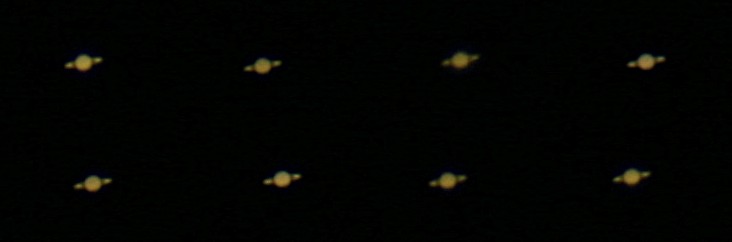
Had hoped to shoot the Pleiades with some longer exposures today, but clouds rolling in prevented that. So some snapshots at ISO100 and 1/4s of Saturn instead. These are 100% crops, so maybe I need to get an adapter for eyepiece-photography for shooting planets at higher magnification?

The clouds caused this round halo-effect around the moon. By 23:00 it was impossible to shoot stars.
Pooling our hardware resources together in the lab, we now have a 102 mm F/9.8 (f=1000 mm) refractor on an EQ6 equatorial mount and either a Canon 20D or a Canon 400D to shoot with. When one camera is coupled to the scope the other one can simultaneously take a wide-field photo. Did not bother with polar-aligning the mount today, so just looked visually at the moon, mars (it happened to be close to the moon), and M42. The moon is so bright no tracking is really needed.
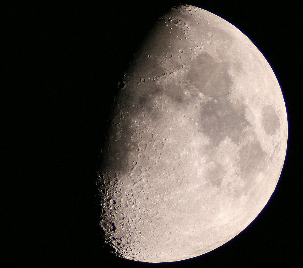
Here is the moon through a 102mm F/9.8 (f=1000mm) refractor with a Canon 400D at prime focus, set to ISO400 and 1/160s. Around 21:40 local time on Friday 15 Feb 2008.
Astrophotography in Finland is a cold hobby, I was somewhat unprepared for the weather so around 60 min in -7 C was enough for me...
I've been reading about the z-map model for 3-axis milling. A working simulation environment would be very useful for CAM algorithm development. Coarse errors in the algorithms can be spotted by eye from the simulation, and a comparison of the z-map with the original CAD model can be used to see if the machining really produces the desired part within tolerance.
Jeff Epler hacked together a z-map model with EMC2 a while ago: gdepth. Perhaps some code/ideas can be borrowed from there.
The z-map can also be used for generating the tool paths themselves (similar to bitmap-mowing here, here and here), but that's more advanced and not the immediate goal.
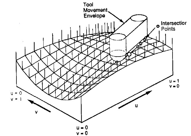
Here's the z-map model, a lot of vectors standing upright in the z-direction, getting cut (or mowed down) by the moving tool. For graphics you could fill each space between four z-vectors with two triangles and display an STL surface. Obviously this works only for 3-axis machining where the tool is oriented along the z-axis, and the tool must also not produce undercuts (e.g. T-slot milling).
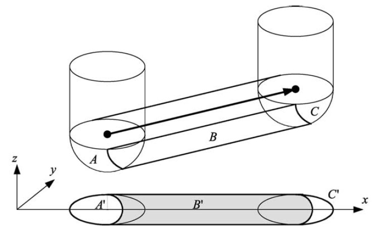
So how do you cut down the z-vectors for each move in the program? For linear moves you can always rotate your coordinate system so it looks like the figure above. The movement is along the x axis, with possibly a simultaneous move in the z-axis. At the beginning of each move (A) and at the end (C) it's very simple, you just calculate the intersection of the relevant z-vectors with a stationary tool at A and C, a kind of 'inverse drop-cutter' idea.
The surface the tool sweeps out during the move itself (B) is more difficult to deal with. The mathematics of the swept surface leads to an equation which most people seem to solve numerically by iteration. I'd like to go through the math/code in a later post (need to learn how to put equations in posts first!).
It's not smart to test all z-vectors in the model against the tool envelope of each move. So like drop-cutter where you are searching for which triangles are under the tool, in z-map you want to know which z-vectors are under the tool envelope. One strategy is simple bucketing, but perhaps if a kd-tree is developed for drop-cutter the same algorithm can be used for z-map.
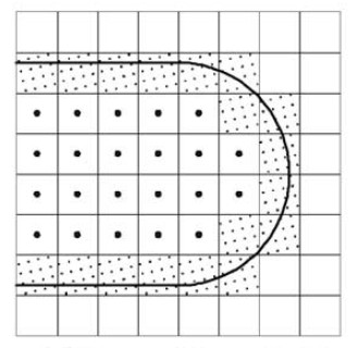
Obviously the z-map has a finite resolution. Increasing the linear resolution by some factor a requires a^2 more z-vectors, storage, and calculations. A better way might be to insert more z-vectors only where they are needed. That's the places on the model where the z-coordinate changes a lot. So here (view from above) for example if you are milling with a cylindrical cutter more z-vectors are needed along the edge of the tool envelope. (I have no idea why they are inserted in a tilted grid-pattern in the above figure...). This potentially leads to much reduced memory/calculation requirements, while still producing a high resolution model. As the simulation progresses there are probably also regions where some densely spaced z-vectors could be removed. Maybe a 'garbage-collector' process could go over the model every now and then and look for flat areas (xy-plane like regions) where less z-vectors are needed and remove them.
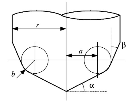
A lot of papers use this APT tool when deriving the equations for machining or simulations. By varying the parameters suitably you get the familiar tool shapes below:
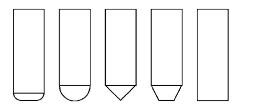
From left to right: Bull-nose/filleted/toroidal, Round/ball-nose/spherical, drill/countersink, tapered, and cylindrical.
My earlier drop-cutter explanations and code only work with the toroidal, spherical, and cylindrical cutters. I'm not sure if it makes sense to write the code for the general APT cutter, or if it's better to optimize for each case (cylindrical and spherical are usually quite easy).
If anyone has made it this far, my sources are the following papers - which are available from me if you ask nicely by email.
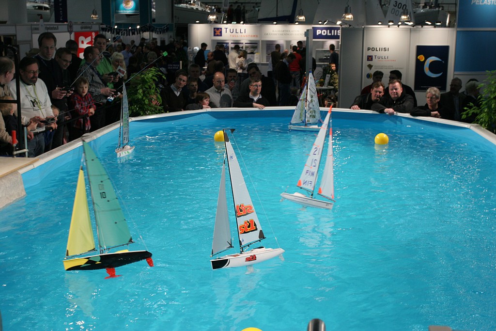
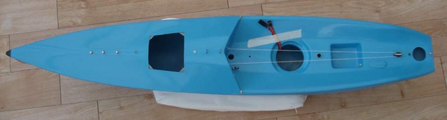
The 2008 Helsinki Boatshow started yesterday with a day for press and other VIPs. Four Micro-Magic boats were sponsored by the Finnish Sailing Federation and its parters, and on Friday a few of the Finnish Olympic sailors got together for some racing in the pool. The show is now open until Sunday 17th, and the Finnish Micro-Magic sailors are sailing in the pool 2-3 times per day for 30 minutes at a time. This pool is a bit smaller, 4.5x9.5 m, than the one at Model Expo last year, but we found some better fans for generating wind. They seem to create less turbulence and a smoother wind across the pool.
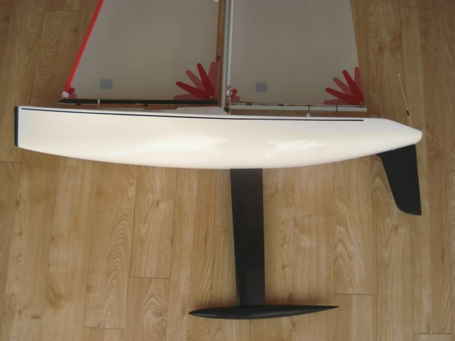
Graham Elliot from the UK doesn't have a website of his own (yet?) , but wanted to let everyone know that he is now building and selling the Widget IOM. Designed by Chris Dicks in 1995 the boat has gone through quite a few changes to everything except the hull shape. The Widget has won the 1996 European Championship, the British National championships in 1997 and 2007, and the 2007 World Championship, not bad for a boat that was designed 13 years ago. The mouldings of the boat are manufactured by Dave Creed.
Graham's options and prices are:
Currently (Feb 2008) there is a waiting list of approximately 16-18 weeks.
Please contact Graham Elliot on elliottyachts "at" hotmail.co.uk if you are interested!