 Jari has been busy planning and building a new spindle for our CNC mill. The project is now about half-way so I thought I'd take a few pictures and write some text.
So far we've been using the stock spindle on the Opti BF20 which has a Morse Taper #2. The original motor burned out at some point so we had to replace it. But as our machine has run for probably hundreds of hours already the bearings are showing some serious wear. We measured a runout of more than 0.05 mm...
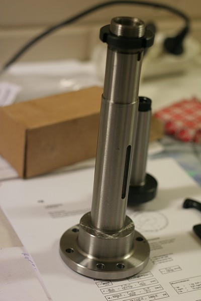
On the left the new spindle, Morse Taper #3, from littlemachineshop, a bargain at $34.95 !. It's sold as a lathe spindle, but we thought we'd get the longest spindle they have to place the bearings as far apart as possible for rigidity.
This is part of a larger upgrade plan for the mill which will include replacing the dovetail ways of the stock mill with linear bearings, replacing the standard acme screws with ballscews, and upgrading the control electronics to use AC servos.
The linear bearings are 15mm wide and manufactured by IKO. We got the ballscews from metallstore (I think they are made by HiWin), and the Sanyo AC servos are from last years surpluscenter sellout of Sanyo AC servos. Three 400 W servos will direct-drive the ballscrews (I hope the torque will be more than enough, otherwise we will have to resort to gearing as is often done with servos). A 1 kW servo will be used as the spindle motor. I'm hoping that using a servo as the spindle motor will allow rigid-tapping eventually. Finding affordable servodrives for the AC motors (sinusoidal 3-phase commutation based on hall sensors and/or 2000 ppr encoder) is not easy, so I've actually had a go at building my own drive (also check out Tero Kontkanens effort).
Everything will be controlled by EMC, with a Mesa Electronics M5I20 PCI-card for I/O.
Some pictures of the spindle assembly and toolholders below...
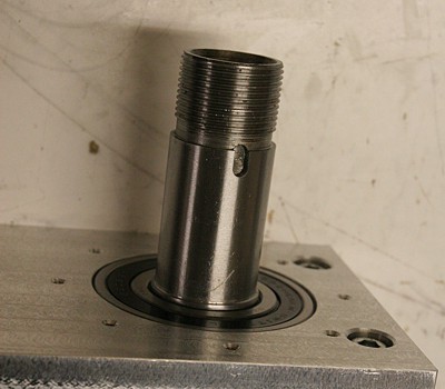
This is the spindle box itself. Circular recesses for the bearigns were first milled and then bored for a tight fit. Runout measured from the inside of the morse taper is now about 0.01 mm or less. Two steel plates will be added to the sides, and another steel plate to the back where the spindle attaches to the Z-axis carriage.

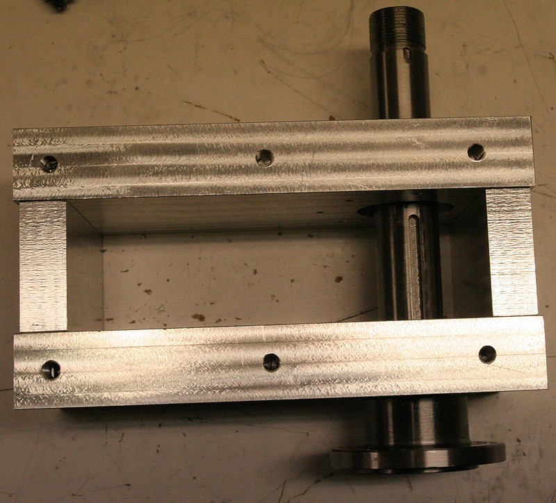
The top and bottom of the spindle assembly. The top end will receive a toothed-gear and a tightening bolt. We are hoping to have two gear ratios to switch between, 1:1 for max 3000rpm, and 1:2 for max 6000 rpm. The higher rpm range will be useful when running finish passes with small mills, something typically done on the IOM fin/rudder moulds we intend to make. We also need to make an M12 draw-bar. The bottom end will require a tight seal to be added which will keep chips and coolant and all the other nasty things that fly around out of the bearing and the spindle box. The bottom end of the spindle has holes in funny locations for some reason...
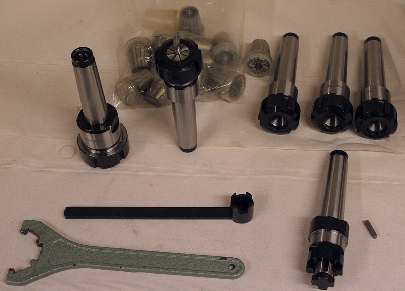
Some toolholders we got recently from Franz Singer on ebay (you would not believe the kind markup domestic distributors have on these things !). To the left a larger ER32 collet chuck which will be fitted with a 20mm collet and hold an edge-finder, used for locating the stock material when setting up a job. In the row to the top right and standing with a 6 mm collet fitted with an endmill are ER25 collet chucks which will be the main type of toolholders used (although kestools sells weldon holders reasonably cheaply). A selection of collets in the bag at the back. To the front right a holder for a face-mill, something that we have often missed with the current setup - hopefully this one will allow us to quickly get stock material into the correct dimensions before beginning a job. Not shown in the picture is a toolholder for our boring-head, and we also need to get a B16 standard holder for our drill-chuck.
are you selling this type of spindles?
thanks
Hi Michael,
The spindle itself is from littlemachineshop.com, we're custom building the spindle box, fitting a toothbelt + gears, motor mount, and mount to Z-carraige.
At this poing we have no plans to make this a product and/or sell it as such. But if there's enough interest in the future - who knows... If you or someone else would be interested in some of these parts then I'm sure Jari could make them for you, but you'd have to send me a drawing and then we'd send you back a quote.
Anders
Looks great. What type of spindle bearings are you using?
Hi Kyle,
the bearings are standard grooved bearings, IBC model number 6206-2RS. cost about 50eur each.
Only time will tell if these are good enough, or if we need something better.
Anders
Hello guys,
I intend to convert a BF20 Vario L to CNC, need some info as I am a total beginner. Want to know what else do I need to change beside the ball screws ( linear bearings, where can I buy from? ) and so on. I need a real precise CNC machine, high precision but not interested in working in very hard steel. What precision do you think can be achieved with a converted BF 20 to CNC and what parts are required?
Also - is there any possibility to buy only the column and the table as I intend to attach my own milling machine?
Thank you
Cristian
Hi Christian,
For cnc-use ballscrews will be much better than the normal threaded screws that come with the Opti. Our ballscrews are 16x2.5mm screws by HiWin and they are bough from http://metallstore.de/
For the ways, some machines use dovetail ways successfully, but we decided to replace them with linear ways. Our guideways are made by IKO, 15mm wide, and bought on ebay. HiWin makes similar ways, available also from metallstore.de
When our machine was running with steppers and the stock screws, if you are careful about the setup and know what you are doing you can probably reach 0,05 mm accuracy for the parts (or a little better).
With ballscrews we are hoping that number will be closer to 0,01 mm
I don't think it's possible to buy the column separately. Opti does sell the cross-tables separately, and if you inspect the models you will see that some of the tables sold separately are exactly the ones used on the Opti mills.
If you are serious about building stuff yourself, and can find someplace with a big mill where the base of your machine could be face-milled, then custom building the base is also an option. Check out the forum om cnc-zone for inspiration.
good luck, and do send me some pictures if you build your own machine!
Anders
Hello Anders, guys,
I only did some investigation about milling machines and decided to build my own since I admit I am obsessed with precision and I will certainly go for ball screws and linear bearings. I took a look on metallstore and found those ballscrews, 16*2.5 to 25*20 , they are all available.
I took a look also at your CNC machine and noticed you' re using 15 mm guideways, and wanted to ask - isn't this too little? I was planning to use 25mm or even 30 mm since I intended to take the same movement approach as the BF 20 vario: X axis table ( down ) carries the Y axis table ( on it ) and the Z axis is executed vertically, carying the milling head. What sizes do you think are fit for normal milling ( also in steel ) and how many guideways per rail are fit?
Moreover, I intend to use only steel plates since I will need some times to machine steel pieces.
A different approach is to have the Y axis down and the X and Z mounts to be vertically and move the milling head. Is this better?
And one question more - do you plan on using the linear bearings on the BF 20 vario?
Is it possible to convert the dovetail table and attach linear bearings to it?
15mm rails:
the rail size you choose will depend on the expected loads. I don't remember the exact specs on the 15mm rails, but if you take a look at them I would think the reasonable forces are well beyond what you can expect for a small mill (i.e. a 10mm end-mill will brake long before the rails will give up)
From a purely accuracy point of view I would also think that smaller dimension rails are actually better ?
We use two bearing blocks per rail, I don't think any more would help.
For a very precise machine I think the key with the rails and ballscrews is to get a machine with good repeatability (zero backlash and play in all directions). Then if there are systematic errors they can be measured and corrected for. Some precise machines use linear glass-scales as a secondary encoder for this purpose. Others just do an interferometric scan when the machine is built and program the control to correct for any nonlinearities or skew in the axis orientations.
design:
most commercial vertical milling machines use a conventional design where the spindle moves with the z axis, and the table moves in y and x directions. If you want a really stiff machine you use a 'carriage' design for the table (see for example the knuth.de site for a good picture)
Yes, we are fitting the 15mm linear rails to the BF20. I would not advertise this for anyone else as being a simple exercise. They do fit if you think about how you want to fit them and the work on the implementation a bit, but it's not a machine that is designed for linear rails. We are not using the stock BF20 spindle or table, we have built our own.
Anders
Hello,
one more question about linear bearings. I was thinking about using HGH35HA, one per rail instead of using 2 HGH15HC per rail. The board on the rail is 42 * 42 cm, and HGH35HA is 14 cm long. It would be placed bellow the board, 2 rails, in the middle of the right and left rail. Would this be better instead of using 4 HGH15HC, 2 on each rail ?
if you have a 420mm plate fixed to a 140mm block then that does not sound very sturdy. if you will be cutting wood, plastics, or light aluminium then maybe it will work. If your cut's are heavier then I would suggest four blocks placed in the corners of the plate. It does require longer and thus more expensive rails.
Have you estimated your cutting forces ? As stated above, for a bench-top hobby machine I believe the 15mm rails will do just fine. A professional machine like a Haas Minimill or Toolroom Mill would use something like 35x35mm rails.
I found the knuth.de picture I was thinking about. It's on the second page of this pdf: http://www.knuth.de/pdf_2007_russisch/Seite_052.PDF
That design seems to be pretty generic for VMCs, so maybe worth studying.
Anders
Hi Anders,
just wanted to ask if you have any idea about the backlash in a 16*2.5 ball screw?
As you said about the linear guide ways, I thought you're probably right and decided to use the MGW15, especially as I am concerned about precision. Is there any play in the railways, on transversal axis? If yes, how much?
we have not measured the backlash of the ball-nut. It has an adjustment screw which adjust how tightly it fits over the screw. With a high tightness I imagine the backlash can be made very small, but with the disadvantage of high wear and more friction. I'll write something more about this when we get the machine assembled and working.
For the rails, there is also no play or backlash that you can feel by hand.
AW
Hi Anders,
I was looking at the spindle on littlemachineshop and was wondering - how do you guarantee the Z-axis movement to be perpendicular to the table ( that is, is paralel to the gravity ? )
Any design on how to mount the spindle to a motor shaft?
What about using very high precision ball bearings, such as ABEC-7 ( P4 european standard ) ( although very expensive... ) ...
I noticed on littlemachineshop they have tapered roller bearings... aren't those bearings better than yours?
Cristi
I think the measured run-out with our basic cheap beatings is around 0,01 mm to 0,015 mm
I don't know if using higher grade bearings would help. It could also turn out that the cheap littlemachineshop spindle is not true to better than about 0,01 mm and using expensive beatings doesn't help.
Do let me know about the results if you try the littlemachineshop spindle with abec-7 bearings or tapered roller bearings.
The spindle (including the spindle box) is aligned to be perpendicular to the table using very thin spacers between the spindle box and the z-plate that is attached to the rails/ballnut.
We haven't measured accurately yet how much the z-rails and the whole column is skewed relative to the true z-axis. In principle this skewness can be compensated for with tilted kinematics in EMC. Column tilt will only be an issue if you use tools of very different lengths, or if the part you are making is very tall in the z-direction.
the motor is connected to the spindle with a 1:1 toothbelt, it's shown here:
http://www.anderswallin.net/2006/12/new-spindle-installed/
the pro machines build the motor itself around the spindle, but I don't know how that could be done on a hobby machine...
AW