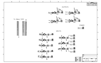
By popular demand, here are the schematics and pcb layouts for the optoisolator cards I made for use with the Mesa Electronics 5i20 servocard.
When using this card with EMC2, a configuration called Hostmot-4 is loaded into the FPGA, making the pins behave as described in the HAL Documentation.
Two 50-pin connectors are used for general purpose IO, one 50-pin connector is used for 4-axis motion control.
The cards will accept standard 50-pin ribbon cables, I've made my own longer replacements to the ones provided with the card.
Optoisolator for general purpose IO
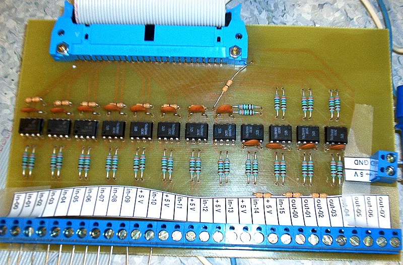
Each 50-pin connector provides 16 inputs and 8 outputs. I'm using the HCPL2630 optoisolator.
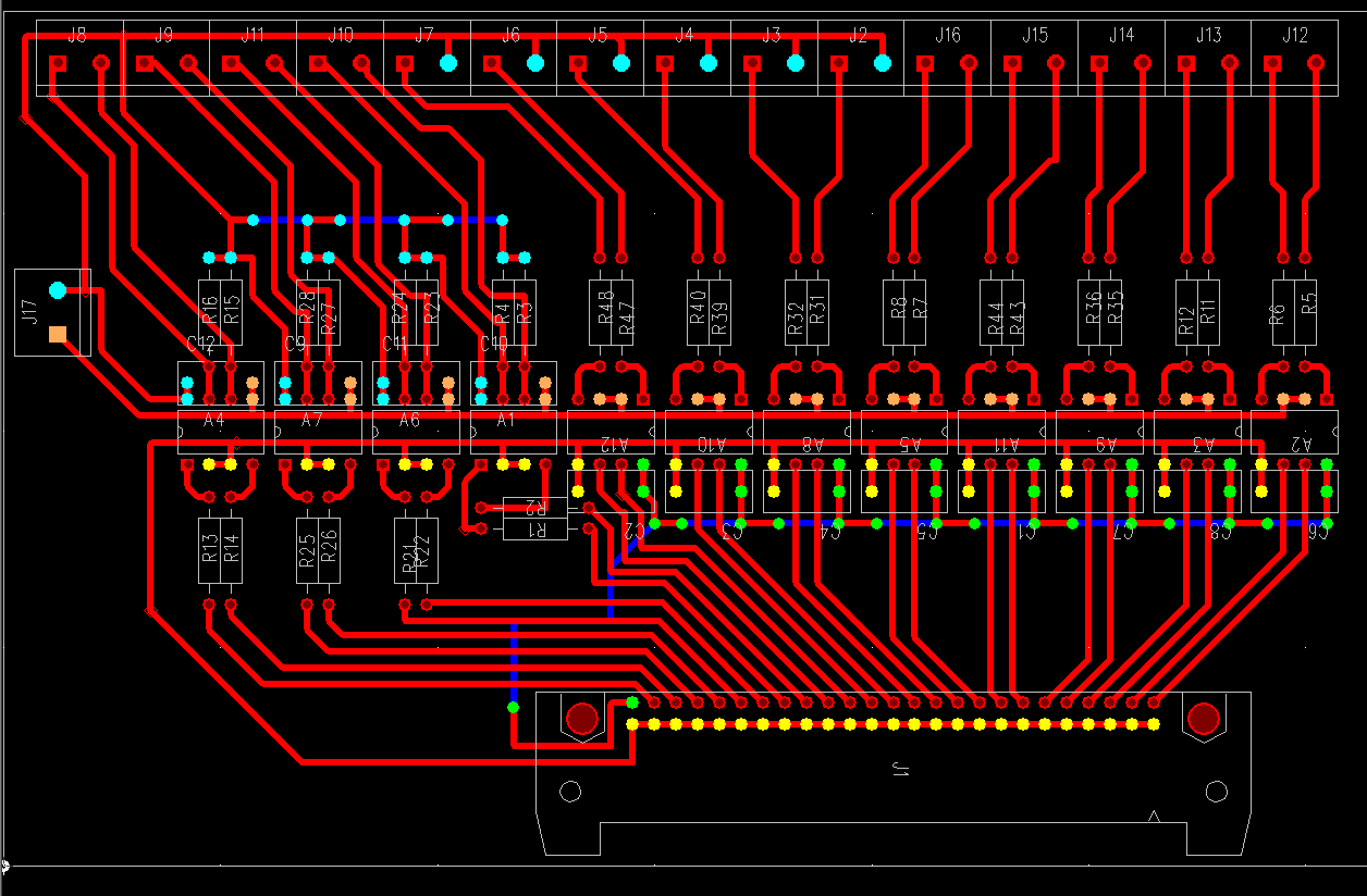
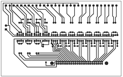
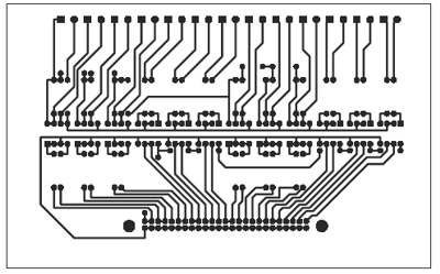
If you are making a pcb, using the mask below, make sure it prints out at the correct scale. The pcb outline should be 100x160 mm.
For some of the outputs I've provided ground connections just next to the input pins. The idea is to use these for switches. By providing a ground pin next to the input I can wire the two ends from the switch neatly to one place on the board.
Like any true engineer I've left out the actual component values from the drawings ! The decoupling caps should be about 100 nF, in my design the current limiting resistors for the LED side of the optoisolator are about 360 Ohms, and the pullups on the transistor side are XXX Ohm. Note that the Mesa 5i20 has internal pullup resistors, so for the inputs to the card, no separate pullup resistors are needed.
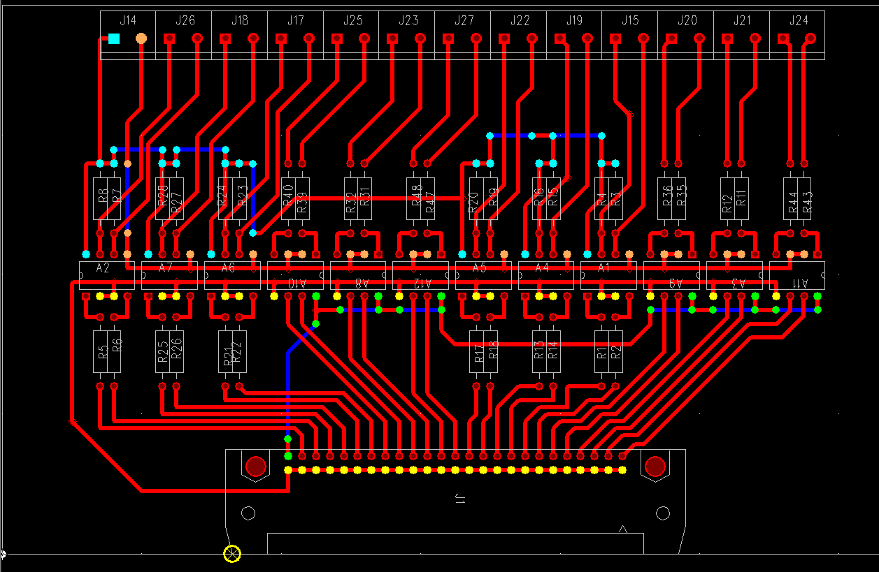
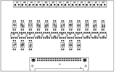
The PCB I made is one-sided. But the circuit requires a couple of connections on the component side too. These are marked in blue in the color figure below, and if you look at the picture above you can see that I've used 0 Ohm jumpers(the beige things) for the component-side connections.
Click the pictures to download higher resolution pdfs.
The original PADS files are also available: schematic and pcb.
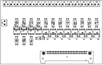
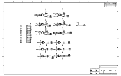
Optoisolator for motor control
This is the optoisolator for the motioncontrol connector. As you can see there are six optoisolators for inputs and six for outputs which makes for a total of 12 inputs and 12 outputs, or 3 inputs (encoder A,B,Index) and 3 outputs(PWM, Dir, Enable) per axis.
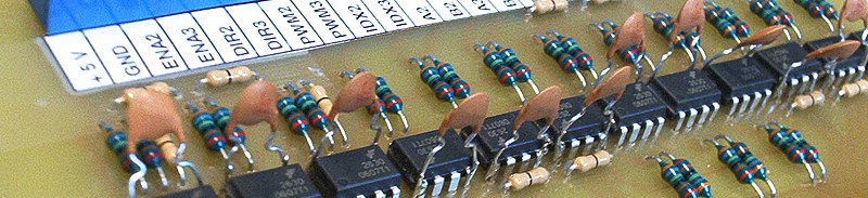
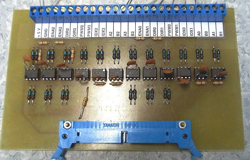
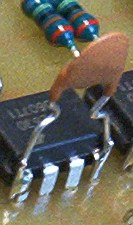 In this first attempt at an optoisolator card I thought I'd save on components and not include decoupling capacitors. That was dead wrong, the card won't work at all without them. So I had to solder them directly to the legs of the chips...
Instructions like above: resistor and capacitor values as above. When building, remember the component side jumpers, and check the 100x160mm boardsize from the printout before making a pcb.
PADS files: schematic and pcb.
Notes
- This is supposed to be an isolator. Don't connect together ground or power (+5V) from the two sides. If you look at the schematic I've used the normal ground symbol for the m5i20 side, and I've called the other side MGND (Motor Ground). Similarly the +5V supplies are separate, '+5V' on the mesa side, and MPWR (motor power) on the other side.
- For optoisolating the general purpose IO, Mesa Electronics also makes a board called the 7I37:
It's much nicer looking than my homemade attempt, and sells for $69. - The design presented above is probably not very efficient or particularly fast and/or smart. I asked for some comments on cnczone, and Mariss Freimanis (of Geckodrive fame) replied with this circuit idea:
Mariss writes: "the HCPL-2531 is cheaper, uses less current and is fast enough. The HCPL-2531 collector current is a paltry 330uA (3.3V / 10K). The PN2222A purpose is to minimize the Miller Effect on the HCPL-2531 transistor by keeping that transistor's collector voltage swing to under 0.6V (Miller Effect is the collector to base capacitance negative feedback that slows the voltage rate on the collector). The PN2222A has a 1mA collector current, adequate for a 1 MHz bandwidth. The isolated-side current consumption is 1mA for logic '0' and 330uA for a logic '1'."
Hello -
I was wondering if you can help out with the Mesa 5i20 configuration. I am using a 7i30 H-Bridge to drive DC Brush motors, So far I have only been able to get the encoders to work, and something seems to not be right with the PID loop, I have no power to the motors. Jogging causes following erros without any response from the motors.
Thanks
-ali
Your following error is a good sign, it means that the encoders are probably working OK.
you should check all components in the chain one by one.
does the motor spin, both ways, when you connect a voltage over the terminals (and reverse the voltage).
does the m5i20 output the correct signals (DIR, PWM, Amp enable) ?
Look at HAL pins with HALscope. Does the motioncontroller output the correct singals (motion-cmd should be the same as the axis position shown on screen).
then connect the PID loop and look with HALscope at the output.
Anders
I'm looking at using the 5i20 with EMC. Perhaps you can say why one wouldn't want to use three Mesa 7i37 boards: one for the general purpose I/O, and two for the motor control? Obviously, this wastes some inputs, as the motor control requires 12 inputs & 12 outputs, but each 7i37 only has 8 outputs and 16 inputs, but using a 5i20 and buying three of the 7i37 is still a lot cheaper than using a Servo-to-go board.
Thanks!
The m5i20 has three 50-pin connectors. In the Hostmot-4 FPGA configuration (the one that currently comes with EMC2) these are used as follows: One for motion control, and two for general purpose I/O. Look in the manual at:
http://www.linuxcnc.org/docs/2.1/
The pinout and the number of inputs and outputs on the 7i37 is well suited for the general purpose I/O connetor (16 inputs, 8 outputs).
It would be quite hard to make a custom cable or connector block or something that would map the pins from the 50-pin motion control connector to a 7i37 correctly.... and as you say it requires 12 inputs and 12 outputs, not 16/8.
I made my optoisolator card for the motioncintrol pins a while ago, but now I'm finding that most servodrives have optoisolated inputs anyway. And the encoder signals probably do not need optoisolation since they run off a separate +5V source. So to conclude it might not be neccessary to optoisolate the motioncontrol part of the m5i20 card since most servodrives have optoisolation anyway.
If you are considering a servo to go (or vital) as an alternative you should note that the m5i20 outputs PWM for motor control, notanalog +/- 10 V as the stg/vital. (Mesa makes a board for converting the dir+pwm signals to +/- 10 V)
Anders
Hallo,
I am currently trying to run a servo system using m5i20 and 7i33 card from Mesa. I am wondering what is the use of the optoisolator card and why do you need to use the optoisolator card as I am reading about your post?
Thanks.
Daniel
Hi Daniel,
Optoisolation is used to protect the computer and the m5i20 from bad things that might happen at the servodrive/motor end.
If for example something goes wrong and the full motor voltage (say 100V) is connected to the logic gates on the m5i20 then it is likely that the card will be damaged and maybe the computer too.
With an isolation stage between the card and the drives it is likely that only the optoisolators will be damaged - card/computer would be saved.
Anders
Hi. These optocoupler board is very useful. I have tried it briefly on a breadboard with a limit switch on one side and the 7i43 on the other side.
However, when I tried Mariss Freimanis circuit. It didn't work. the circuit acts like there is a short between gnd and the pn2222 collector. So the signal is always on. Maybe I mess something on the breadboard. Have you successfully tried his circuit?
Thank you very much.