How accurately can you in principle measure temperature with an RTD or thermistor?
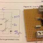
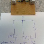
If we push a current  through the resistor we'll get a voltage of
  across it. Now as the temperature changes the resistance will change by
  where
where  is the temperature coefficient of the sensor. This will give us a signal

On the other hand the Johnson noise across the resistor will be
 where B is the bandwidth, and we get a signal-to-noise ratio of
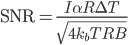
The noise-quivalent-temperature (NET) can be defined as
 or
or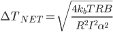
Here we can identify
 as the power dissipated in the resistor and simplify to
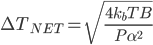
Here's a table with some common values for pt100 and 10k NTC thermistors. The sensitivity is determined by the sensor type. What limits  is self-heating of the sensor which probably should be kept to a few milli-Kelvins in most precision applications. Thermistors with their higher sensitivity are an obvious choice for high-resolution applications, but the lower of a pt100 sensor can be compensated with a larger since most pt100 sensors are physically larger and thus have lower self-heating. pt100 sensors require 4-wire sensing, slightly more complex than a 2-wire measurement which is OK for a thermistor.
| Sensor | Resistance | Sensitivity (divide by R to get alpha!) | Dissipated Power P | Noise-Equivalent-Temperature (1Hz bandwidth) |
| pt100 | 100 Ohms | 0.391 Ohms/C | 100 uW (I=1mA) | 3 uK |
| NTC Thermistor | 10 kOhms | -500 Ohms/C | 9 uW (I=30uA) | 0.9 uK |
I conclude that it is not entirely obvious how to choose between a pt100 and a 10k thermistor. The thermistor is intrinsically more sensitive, but with good thermal contact to its surroundings self-heating in a pt100 sensor can be minimized and the same noise-requivalent-temperature achieved. In any case it looks like Johnson noise limits resolution to 1 uK or so in a 1 Hz bandwidth. If we AD-convert the voltage at 24-bit resolution (16M states) we can get a reasonable measurement range of ~32 K by matching 1 LSB = 2 uK.
Does anyone know of similar back-of-the-envelope calculations for other sensors (Thermocouples, AD590)?