manual pulse generator.

Tag: CNC
JHQ Lathe
I've bought a cnc-lathe!
Well, it's not complete, more of a cnc-lathe project.
A fellow Finnish cnc'er "JHQ" started this project a few years ago, but as he now has a 5000 kg professional cnc-lathe and his own company, he hasn't had time/money to complete this project. There are many project logs out there with details of how the machine was designed and built:
http://cnczone.com/forums/showthread.php?t=27031
http://www.cnc-tekniikka.com/CNC-forum1/index.php?topic=121.0
http://www.robosota.fi/foorumi/viewtopic.php?t=935
http://www.devonparkour.com/ukcnc/forum/viewtopic.php?f=6&t=9
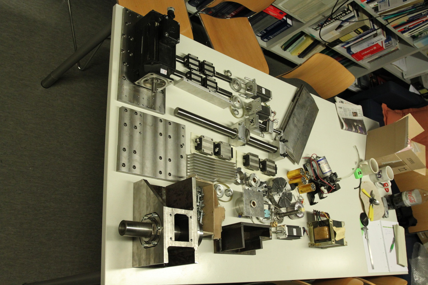
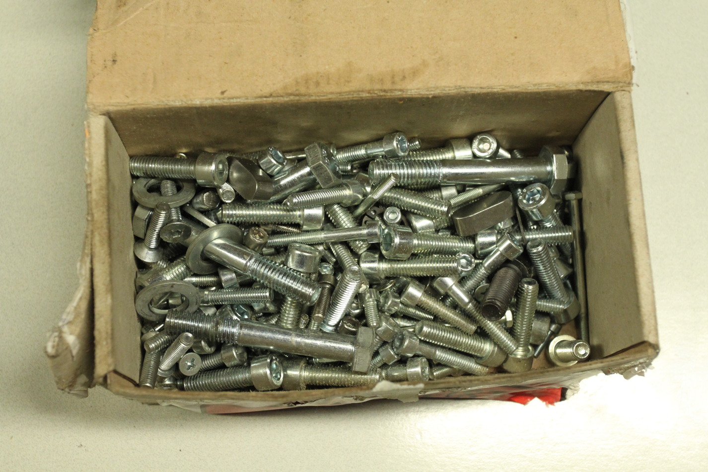
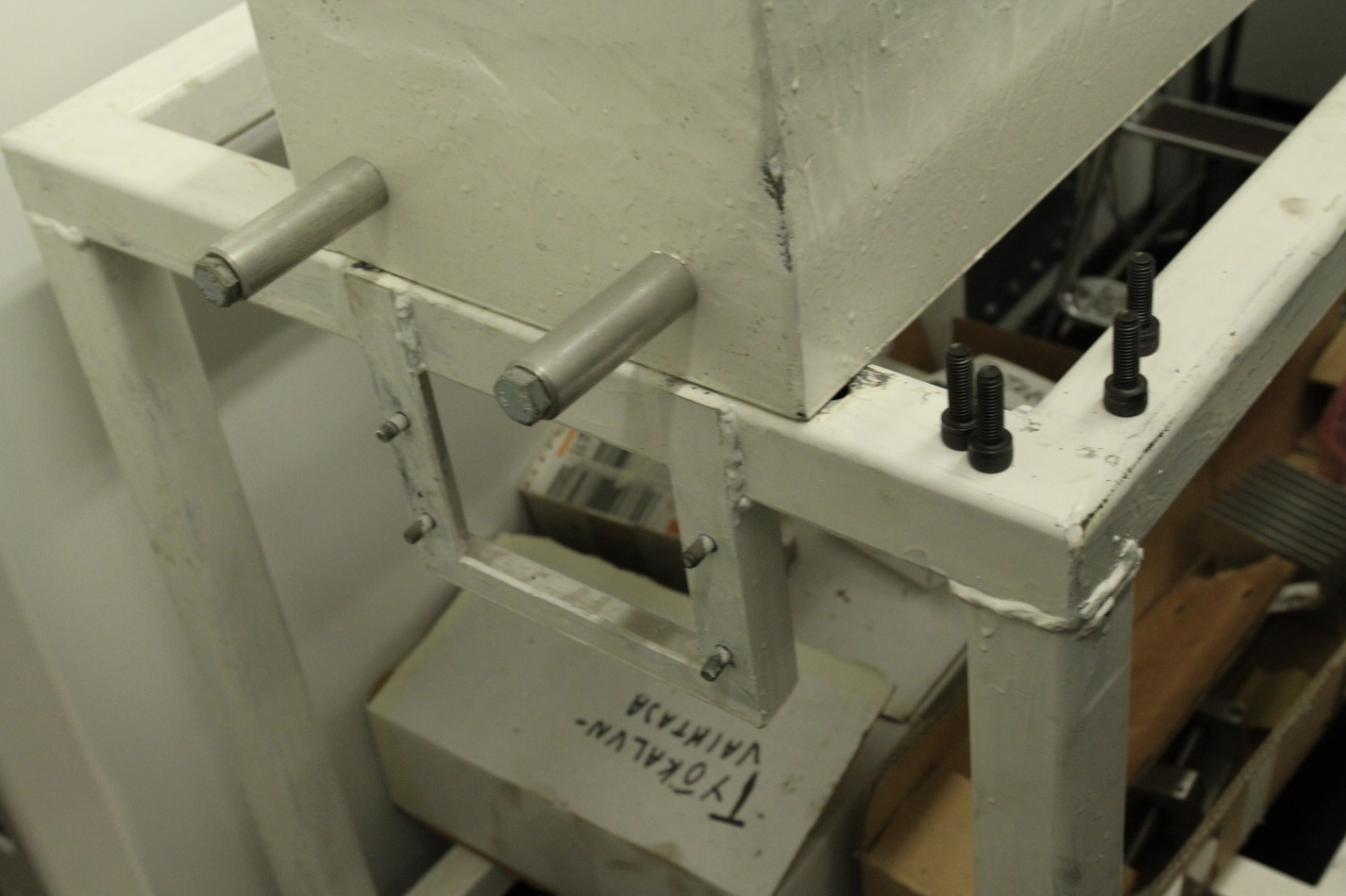
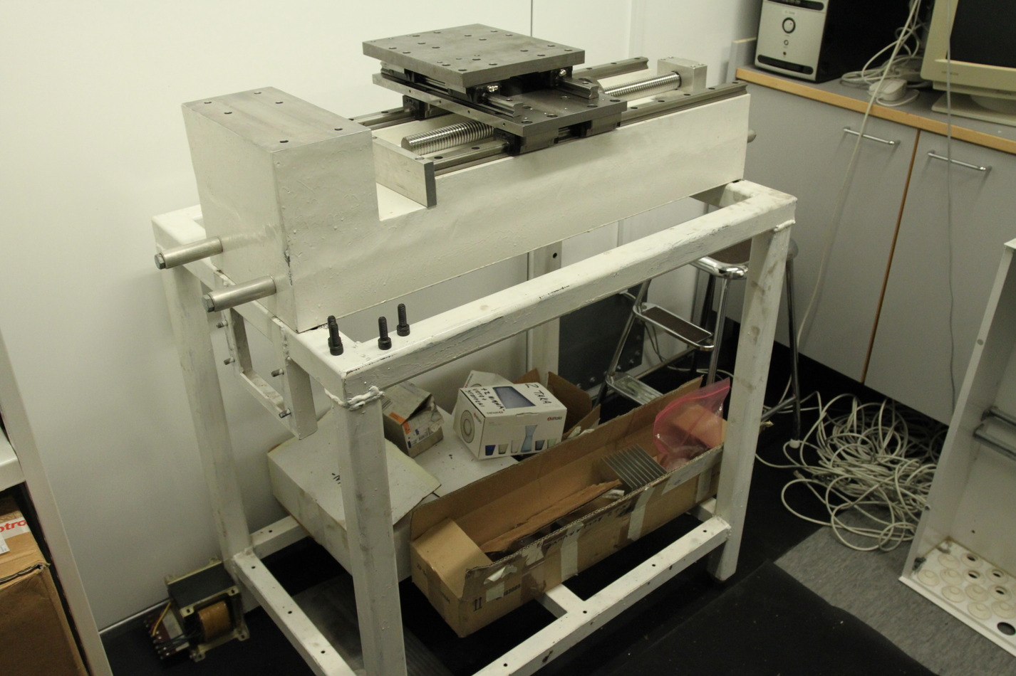
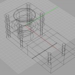
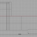
Some notes of my own, as I unpacked everything today.
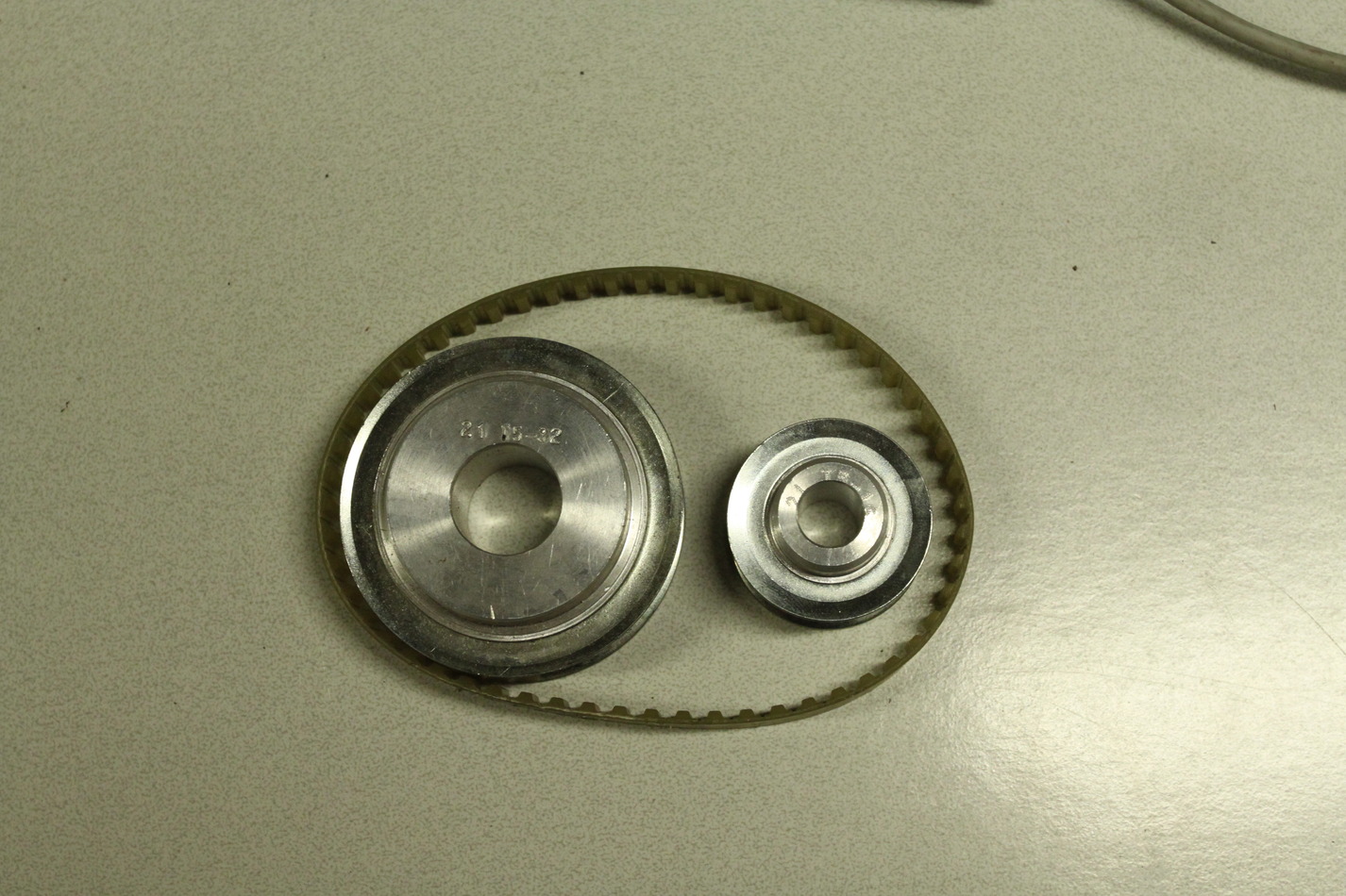
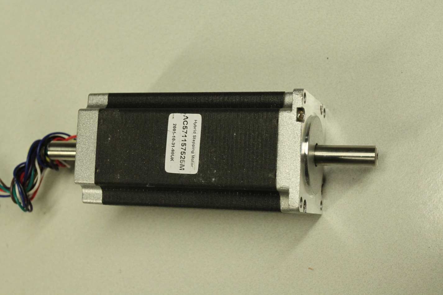
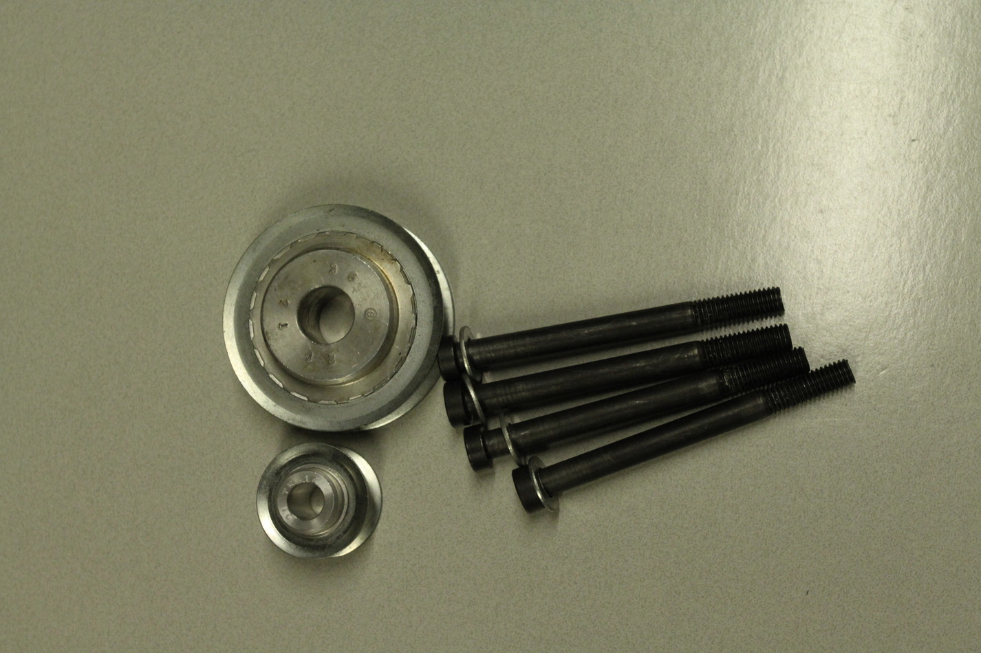
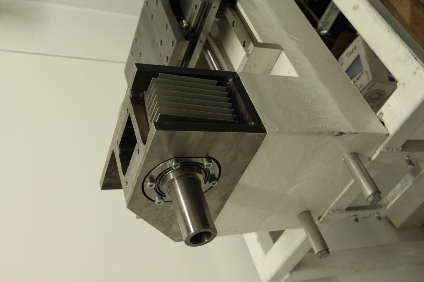
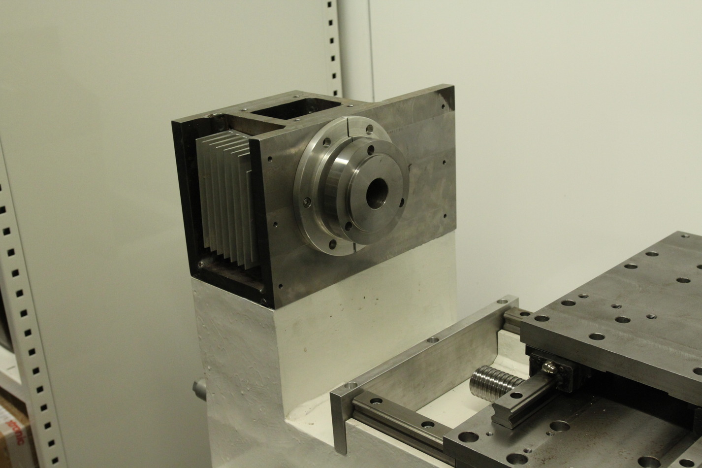
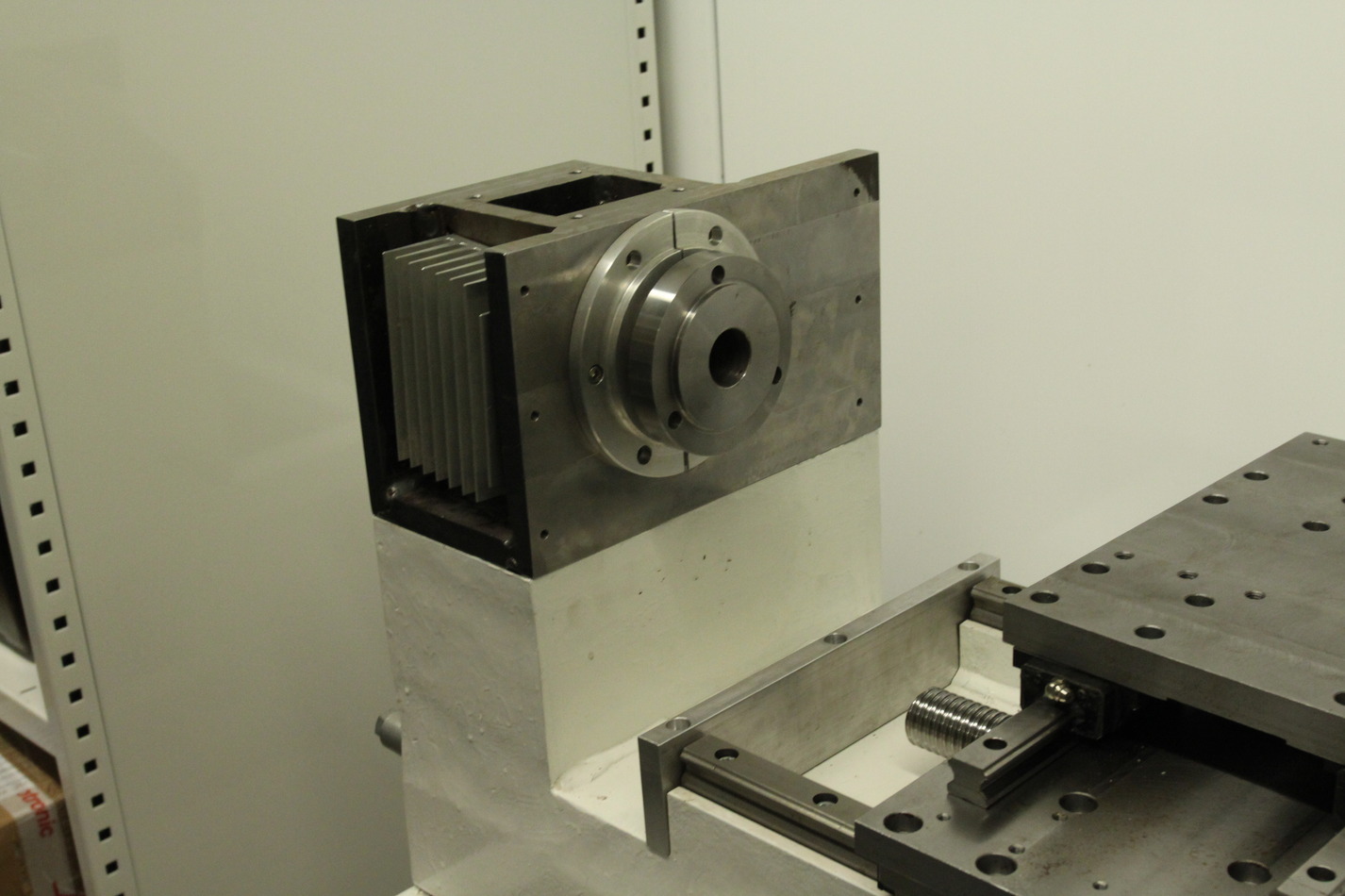
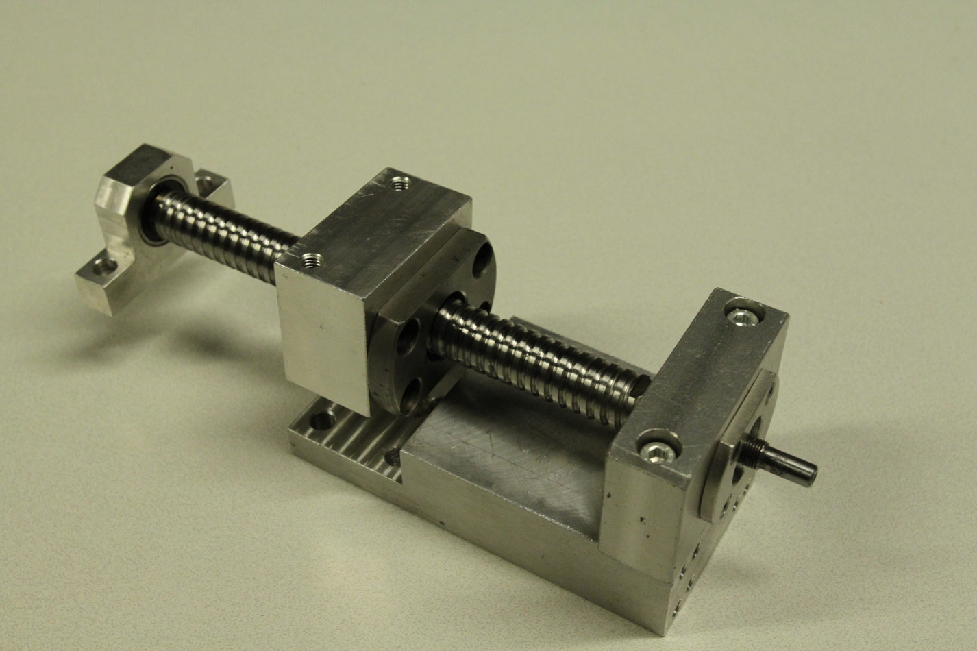
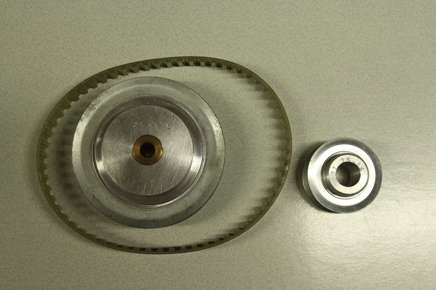
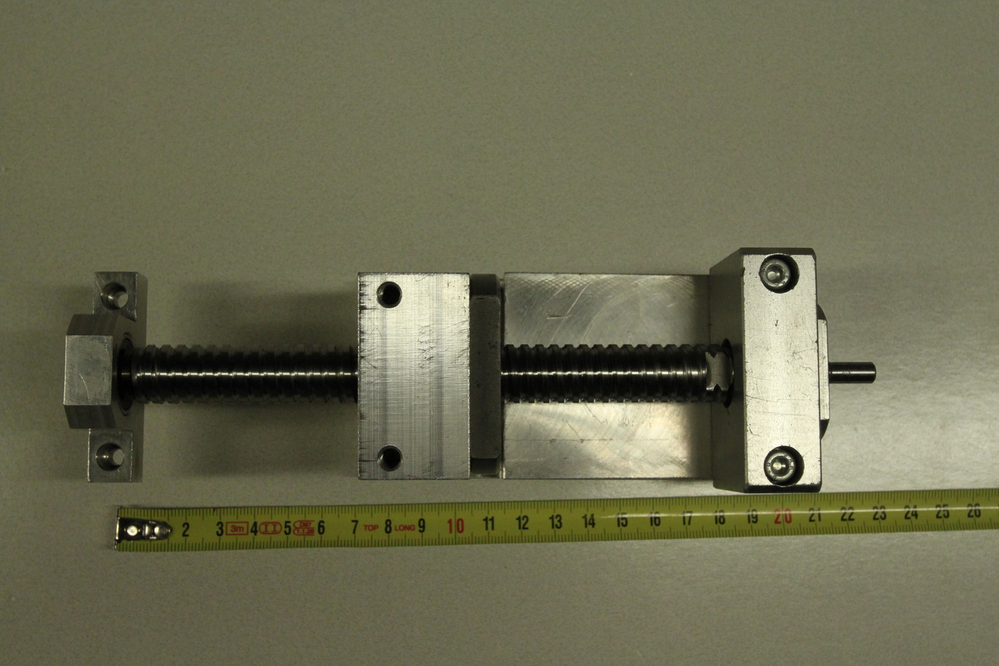
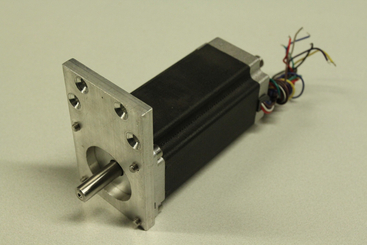
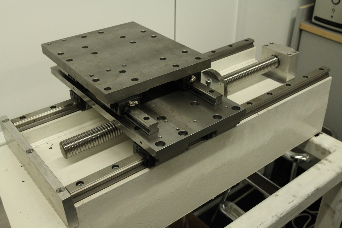
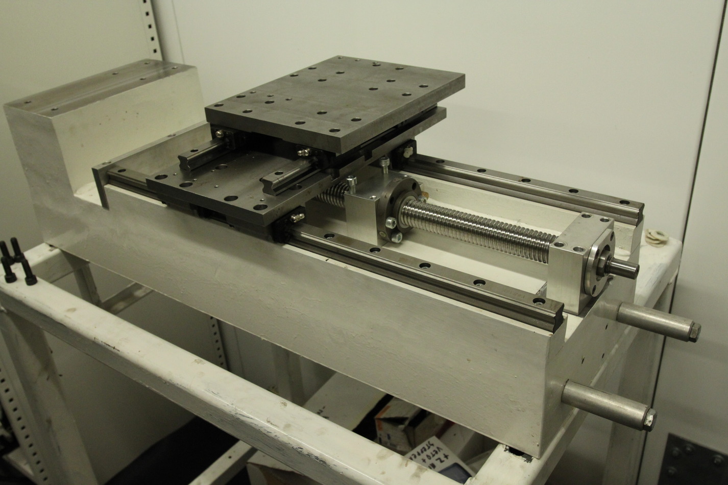
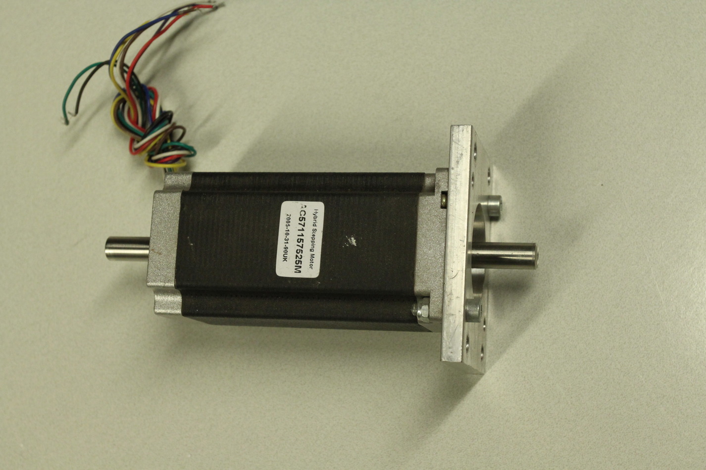
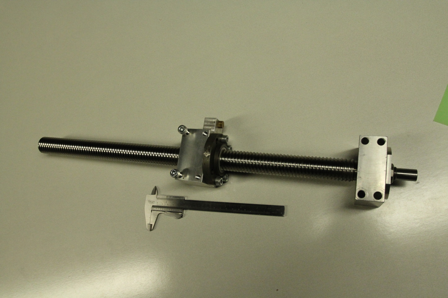
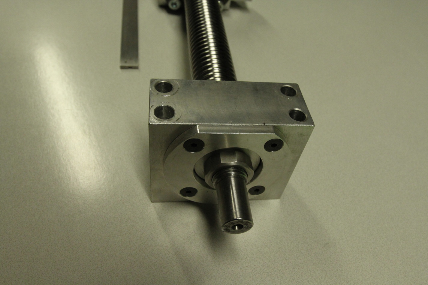
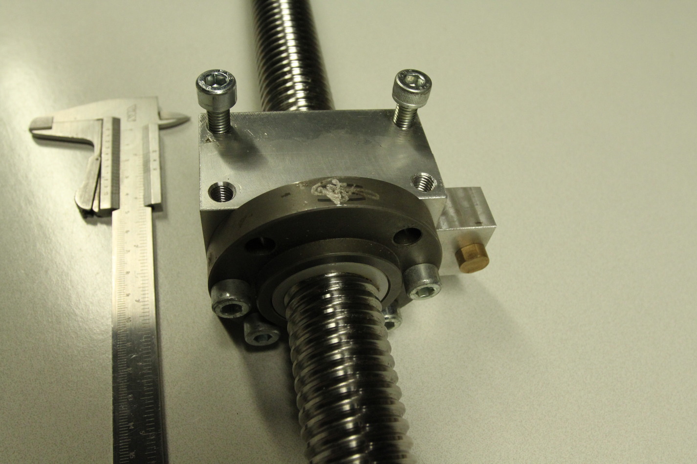
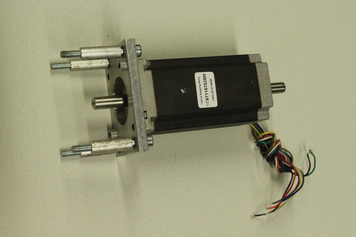
Stepper motors are NEMA23 size with 10 mm diameter shafts (ca 20 mm long). I will most probably not use stepper-motors but NEMA23-size brushless servos instead. The X-ballscrew is 16mm diameter with 4mm lead. It is 158mm long while the nut is 37mm long. That makes for a theoretical max travel of 121mm (enough?). The timing belt pulleys for both Z- and X-axes are type 21T5-36 and 21T5-21 or 21T5-16. That makes for a 1:1.7 or 1:2.25 reduction ratio. The Z-ballscrew is ca 30mm diameter with a 5mm lead (might be 0.2" also). It is 545mm long, the nut is 63mm long, theoretical travel 482mm.
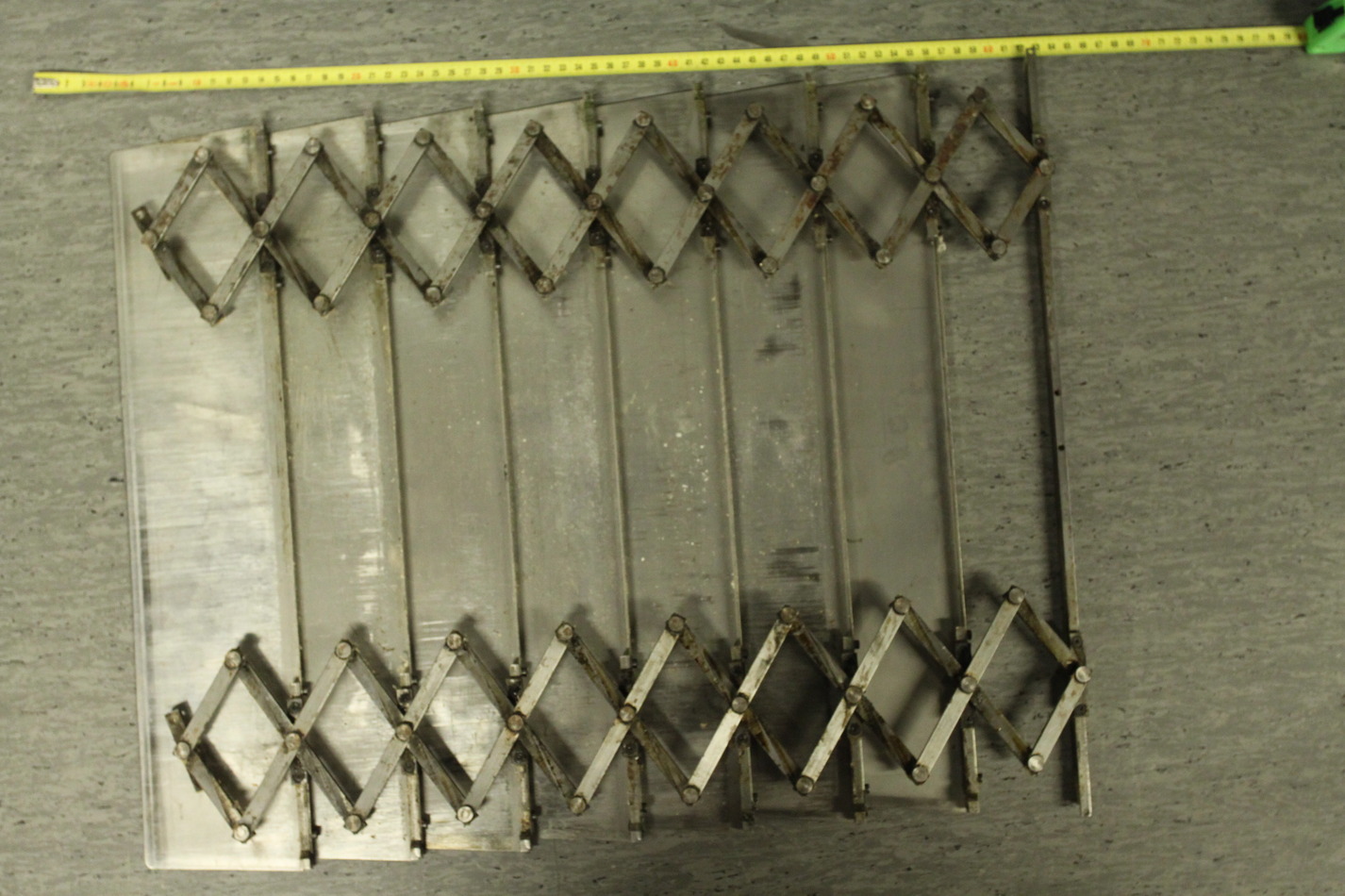
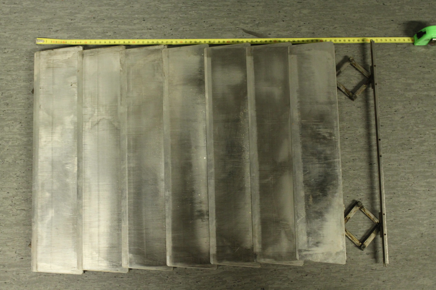
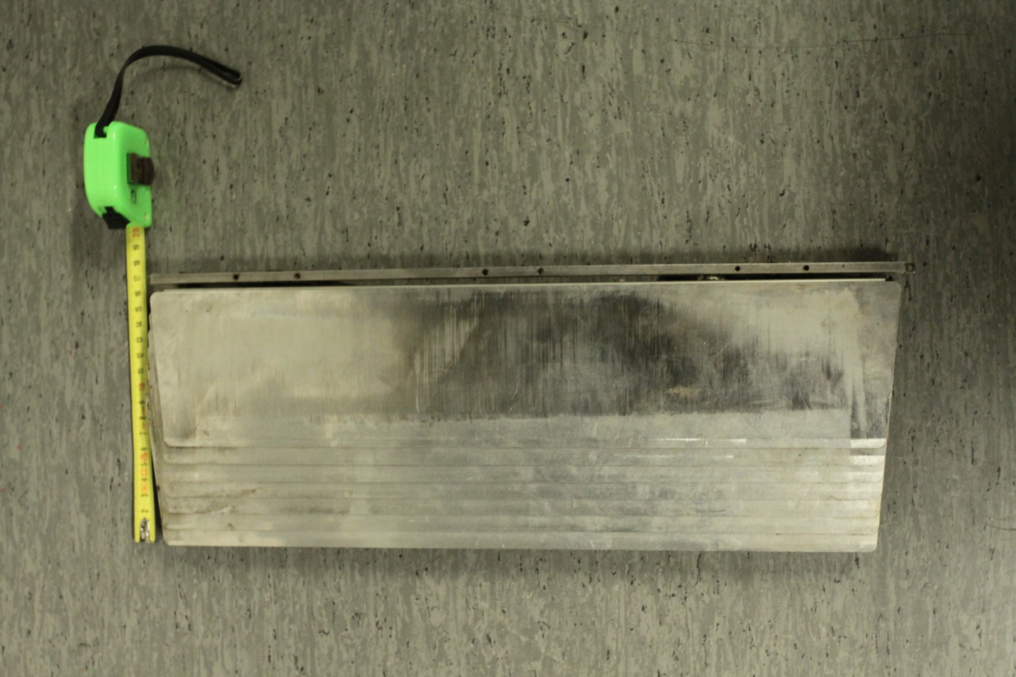
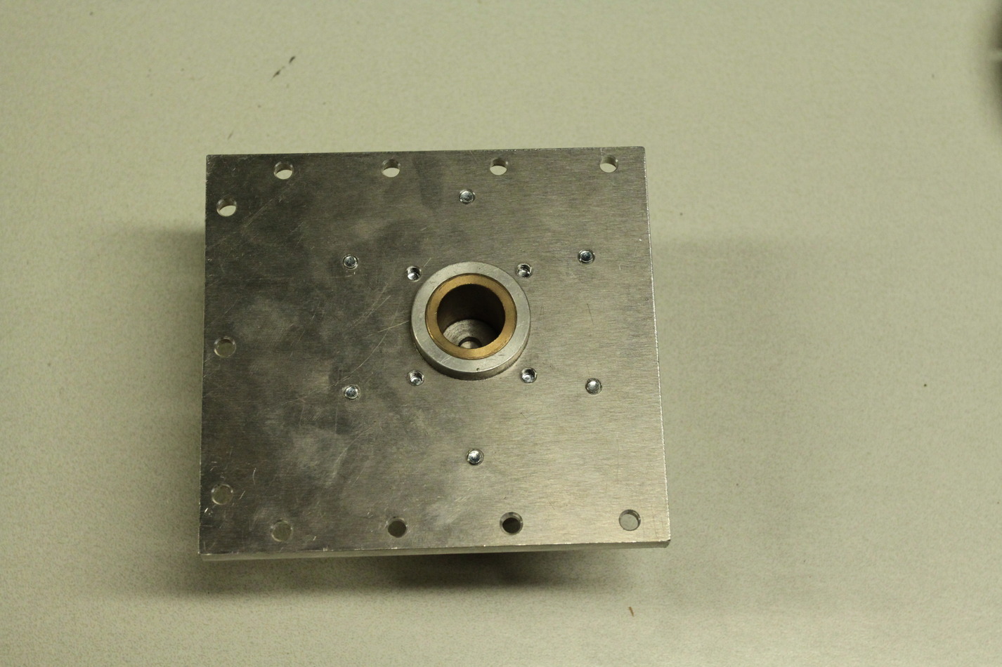
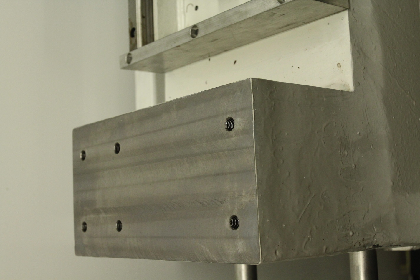
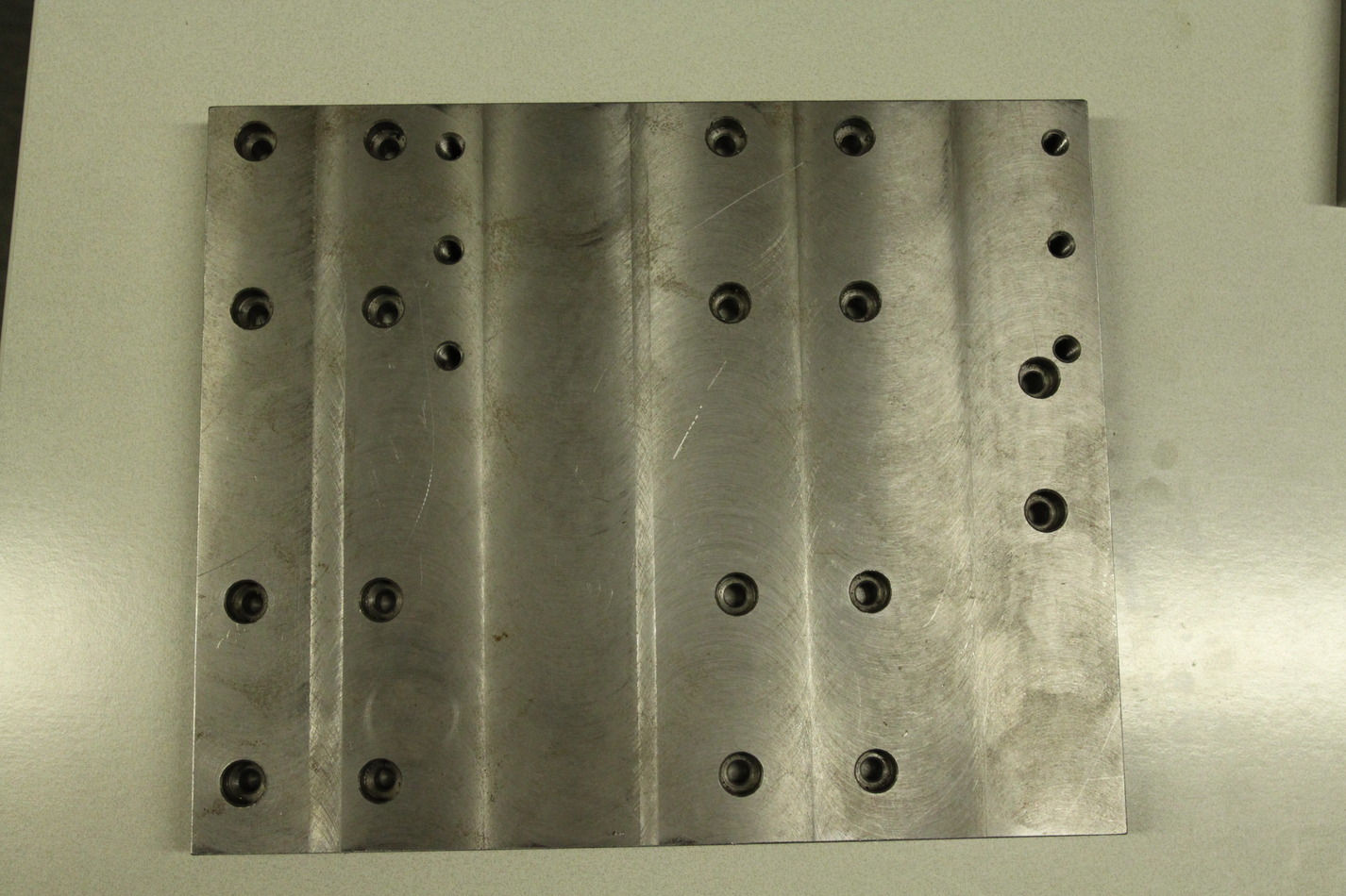
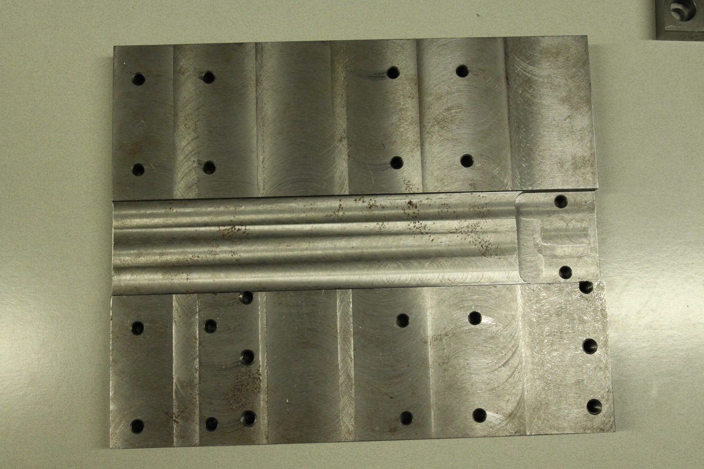
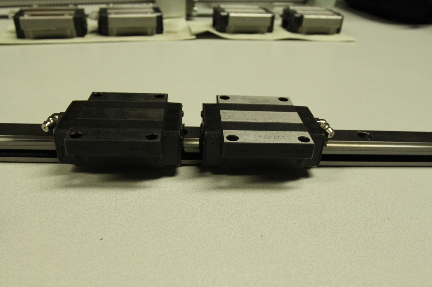
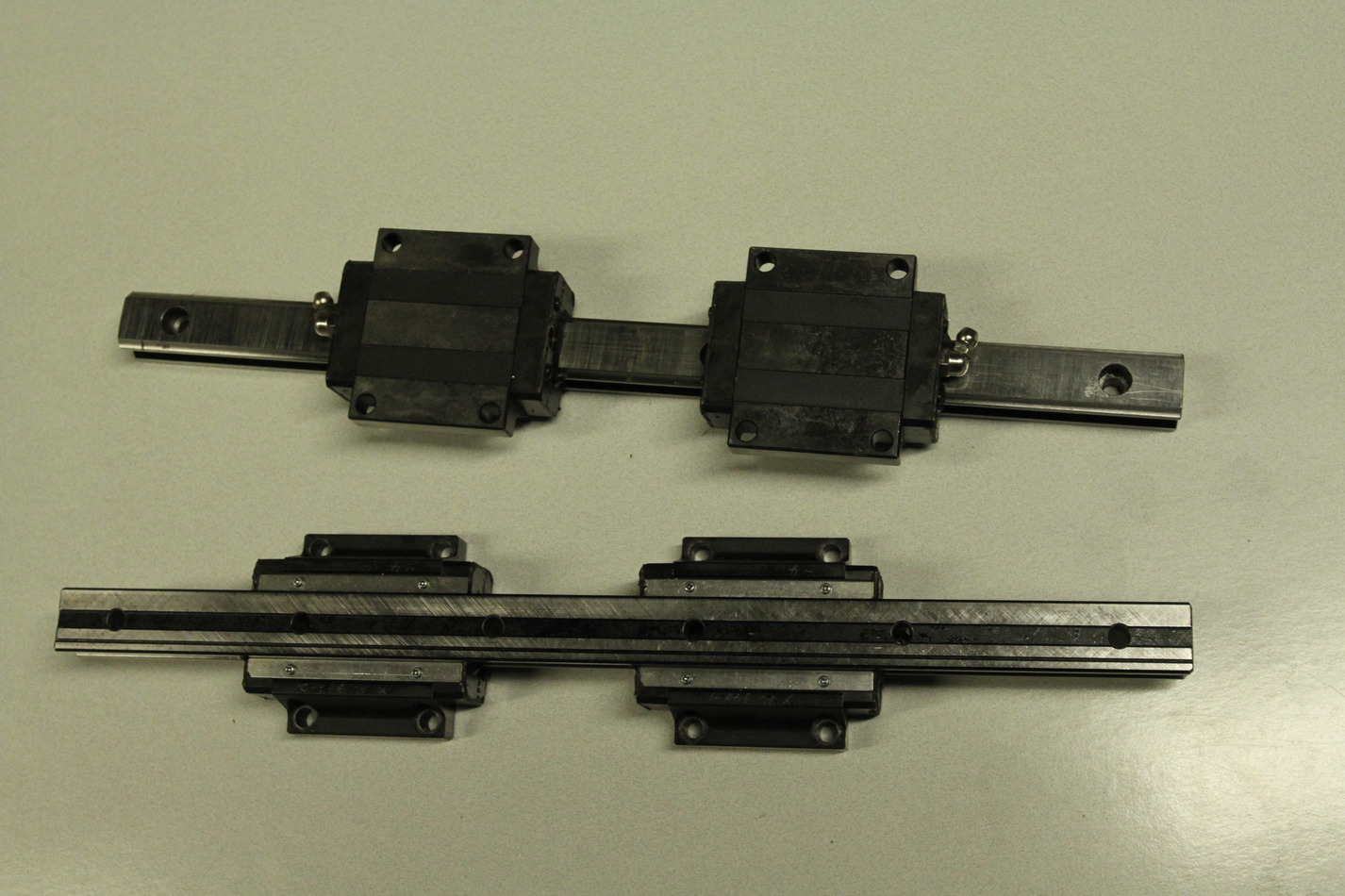
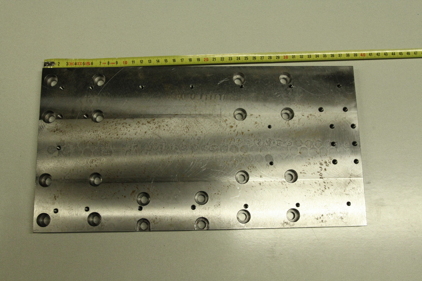
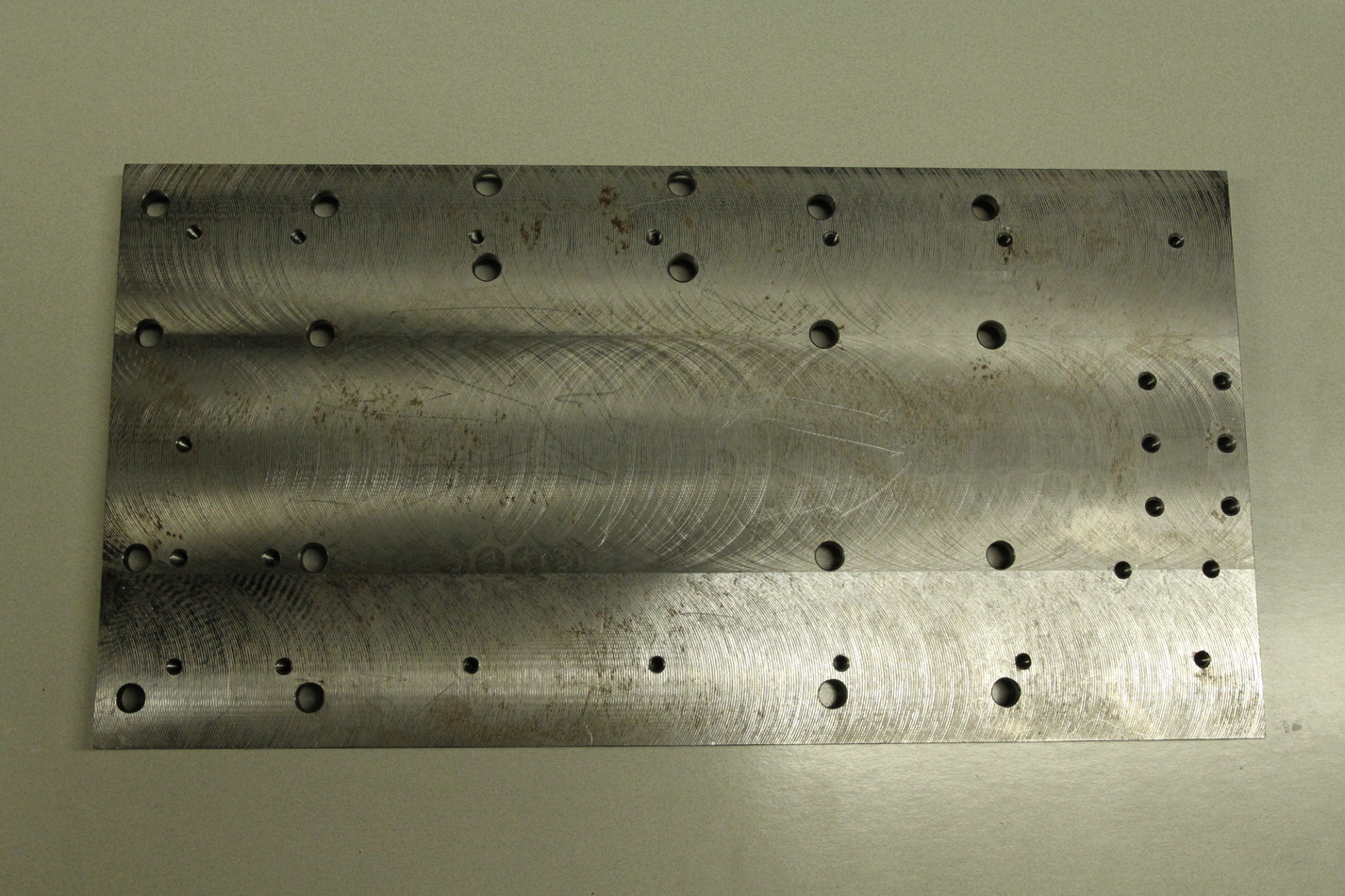
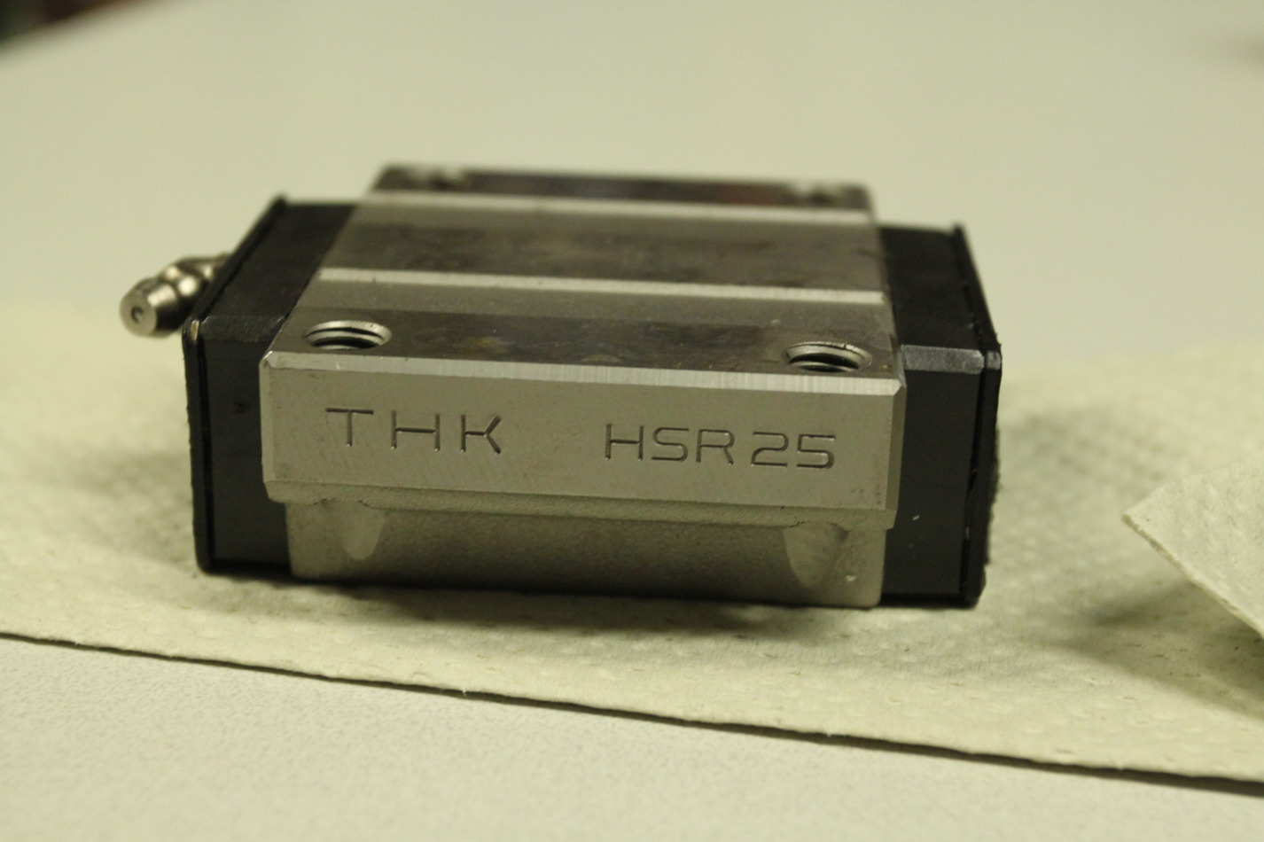
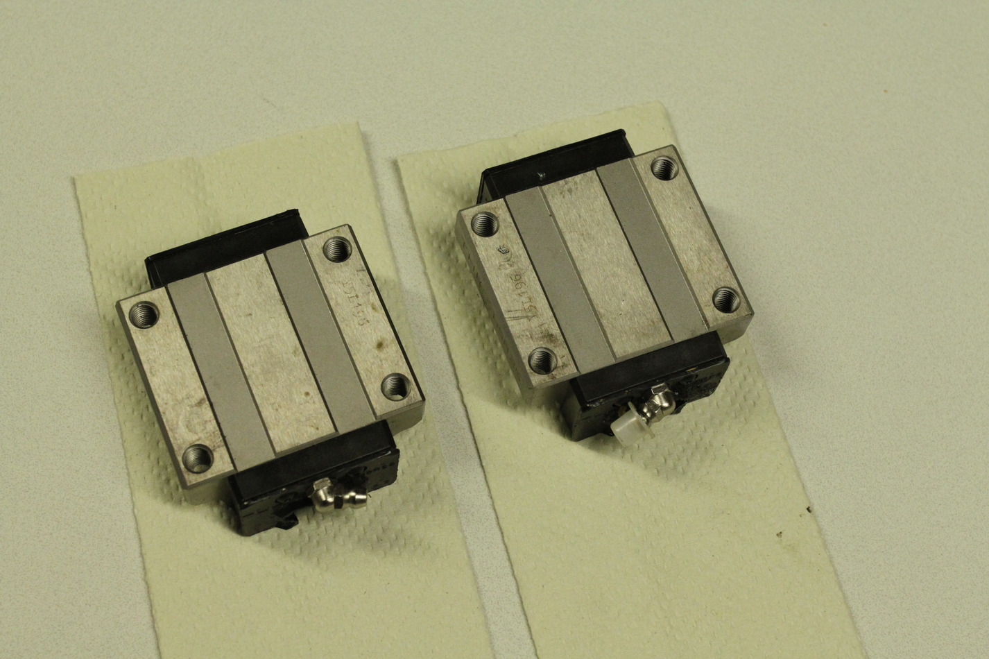
The chip-guard is ca 450-460mm wide and around 185mm long when fully compressed. It extends to much longer than required. The Z-rails are HSR25 type and the X-rails are HSR20 type (length 340mm). The Z-saddle-plate is 380x195x15.3mm. The X-saddle-plate is 275x227x20.4mm.
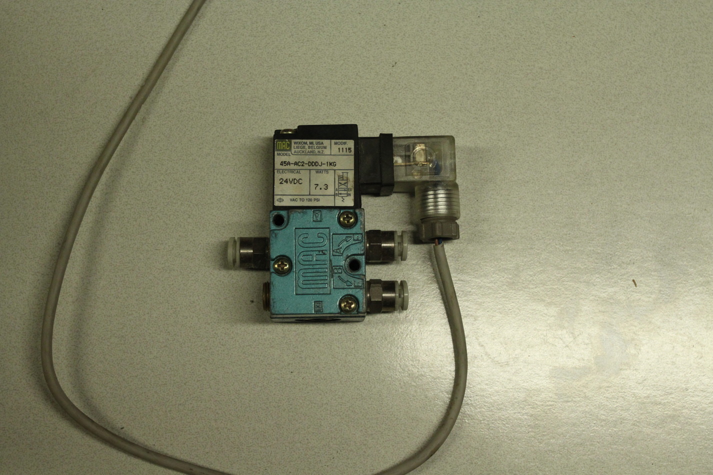
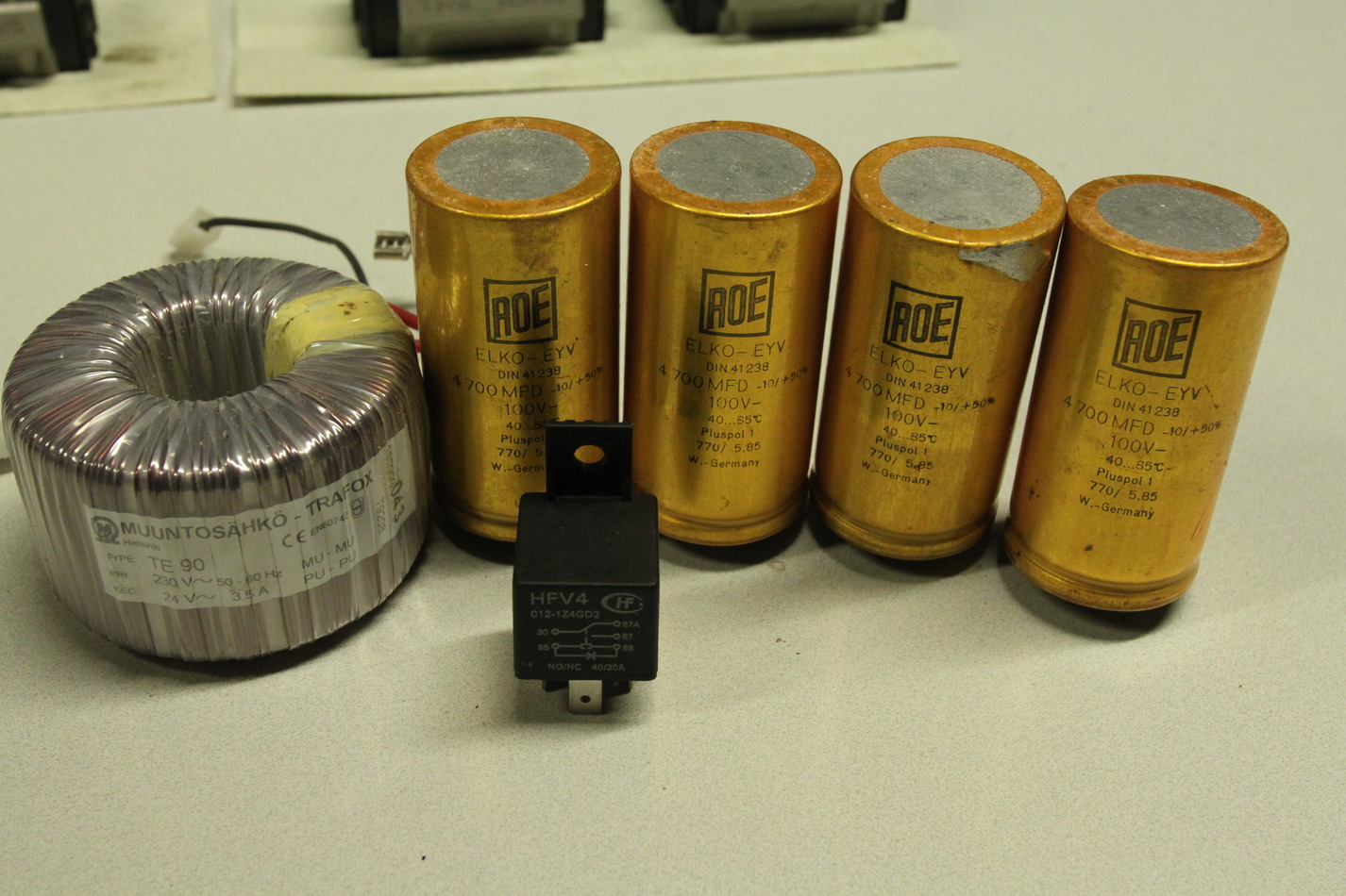
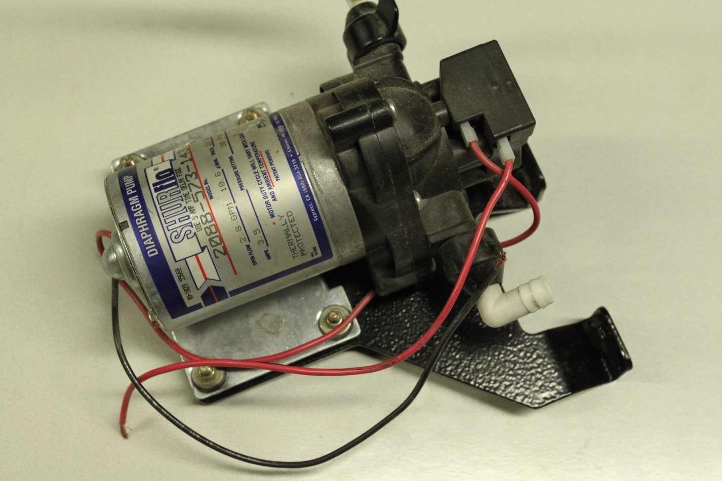
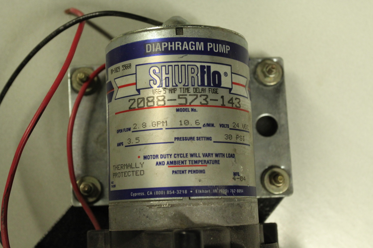
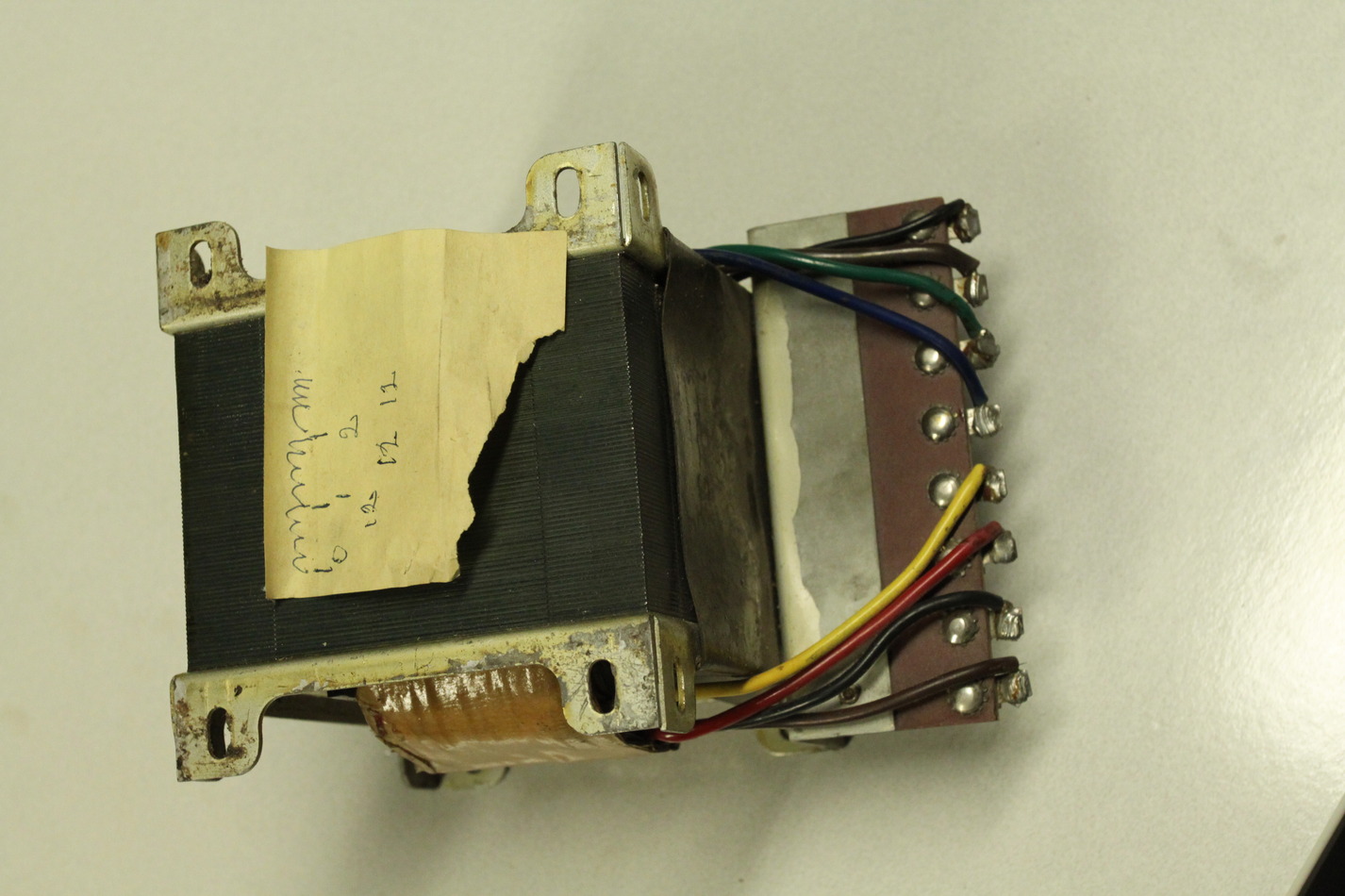
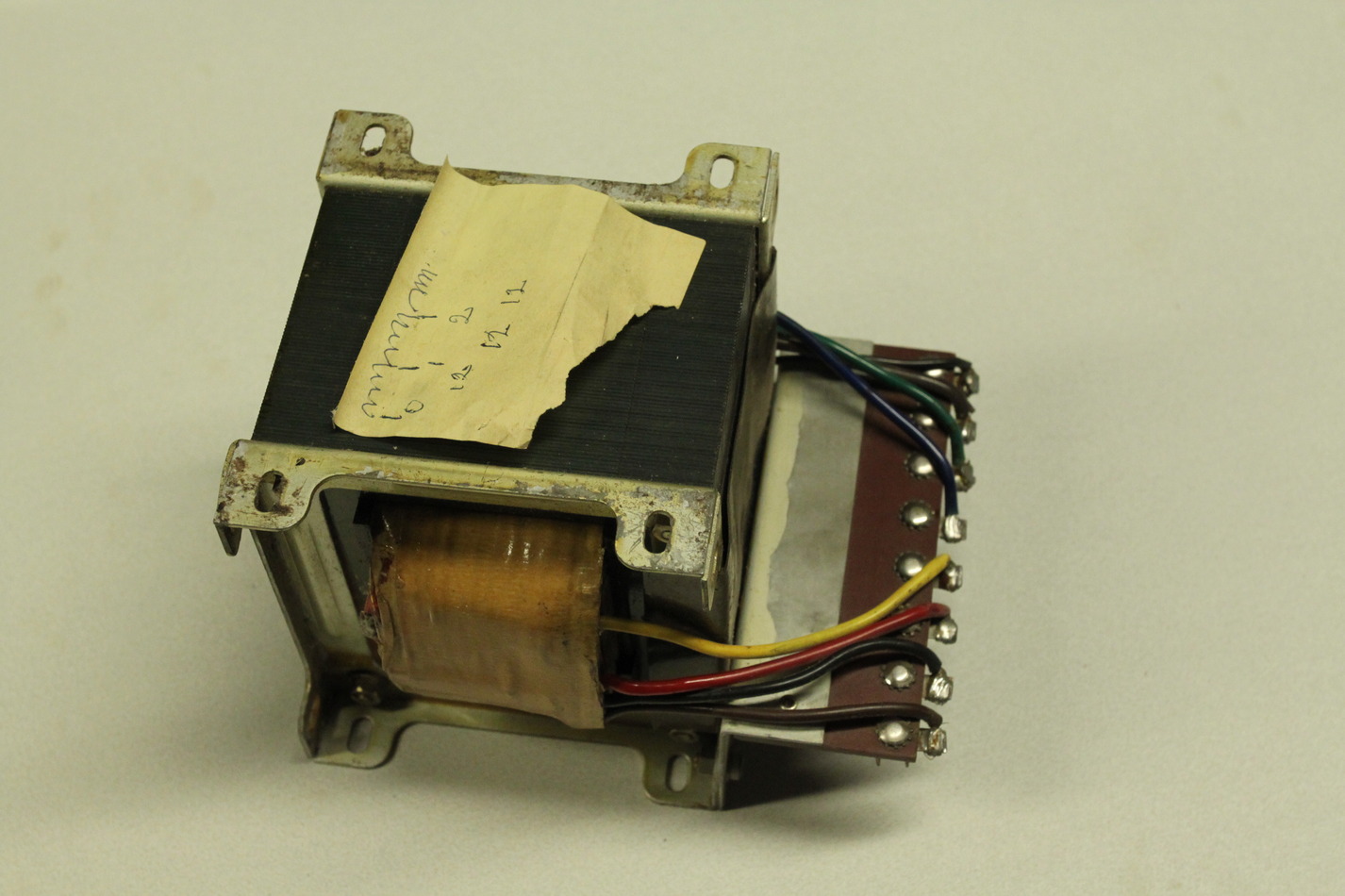
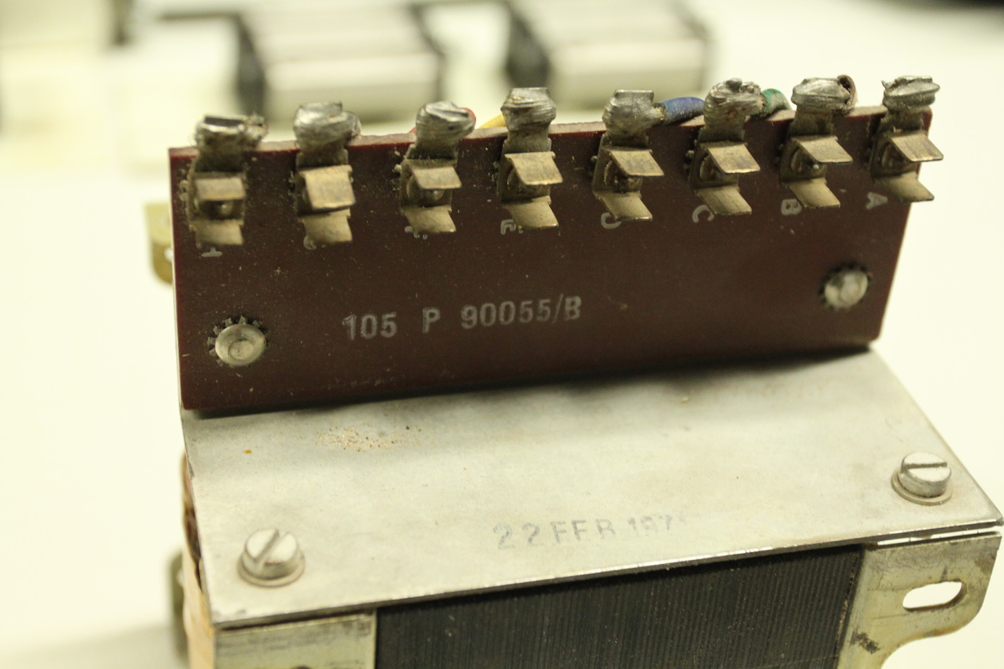
The coolant pump is rated as 24V/3.5A. There is a transformer with a 24V/3.5A secondary for powering the coolant pump.
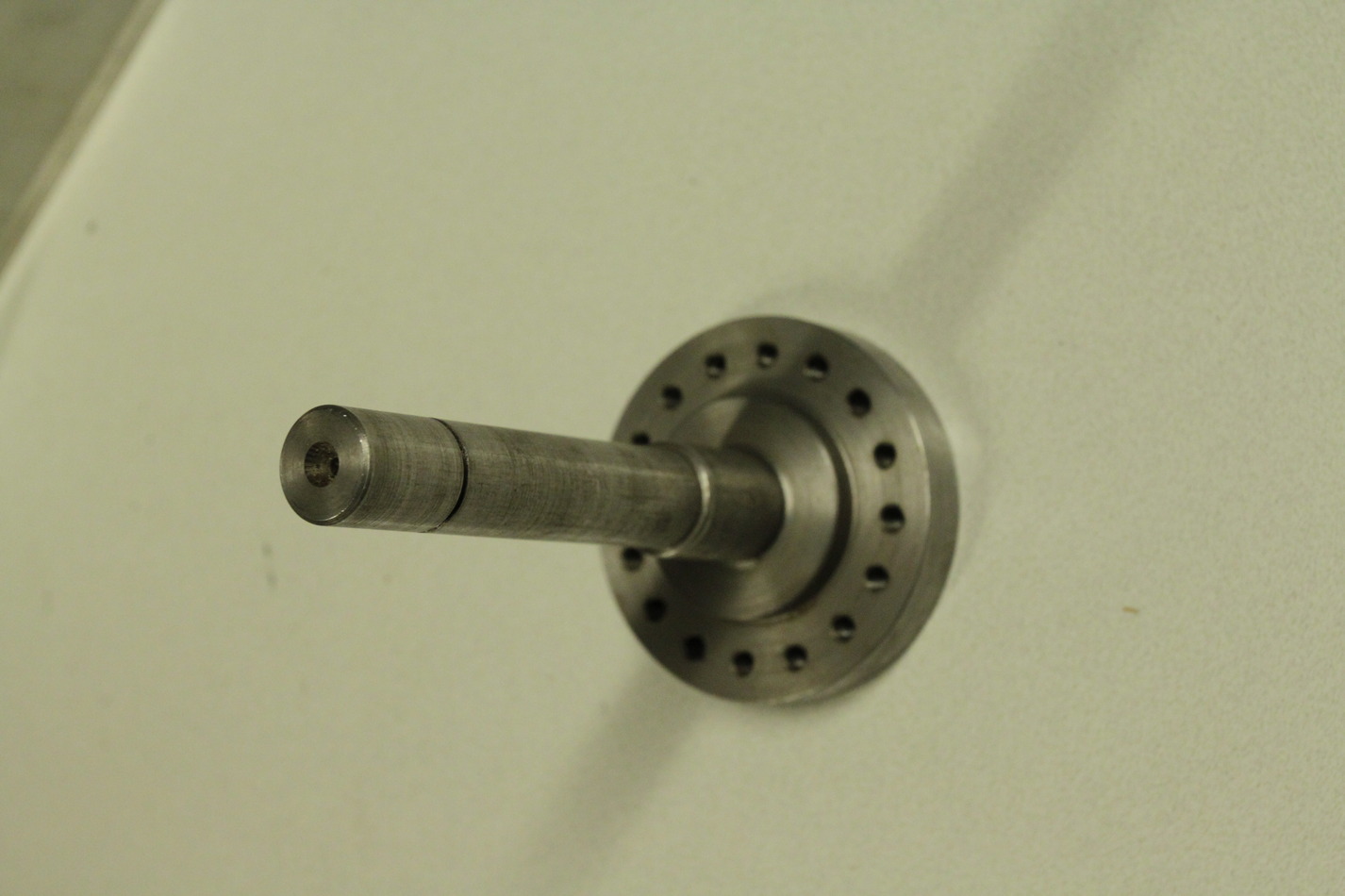
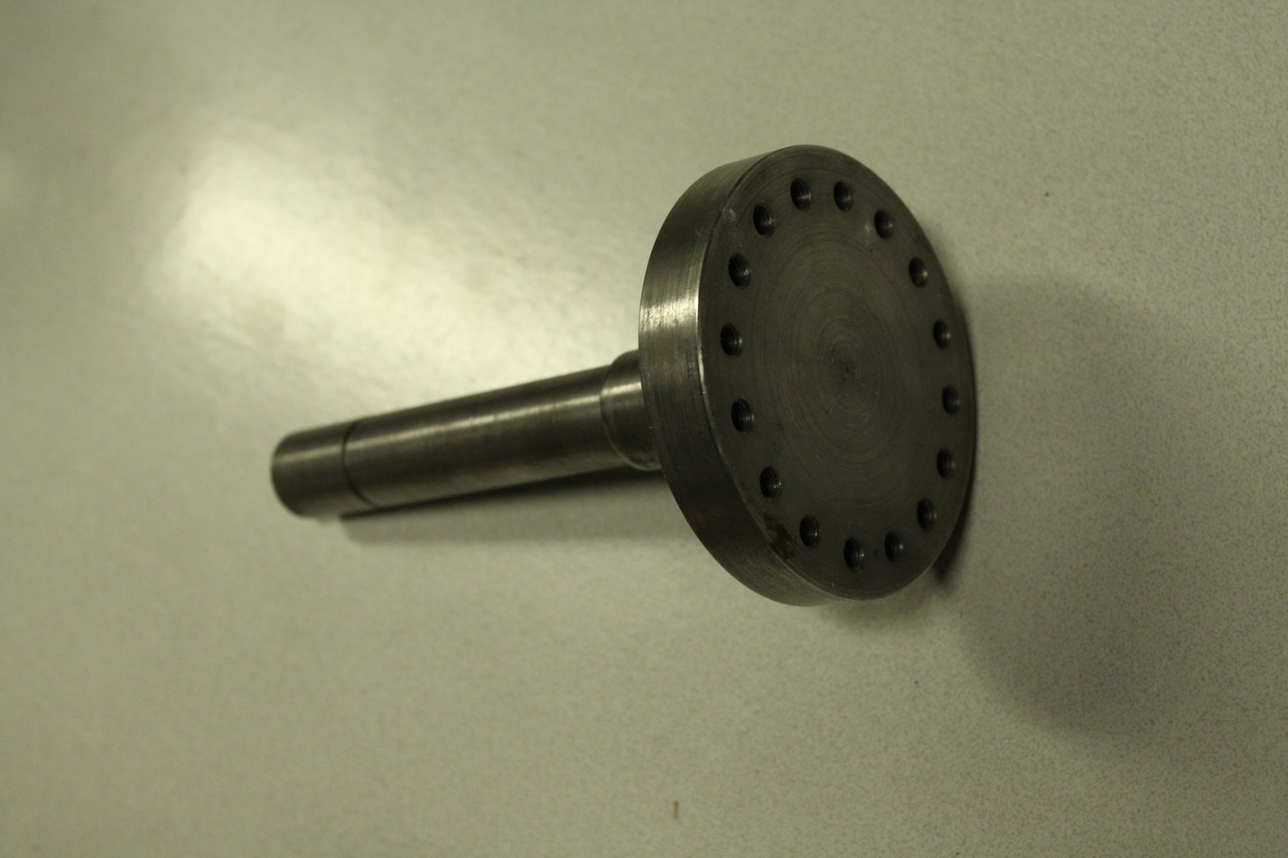
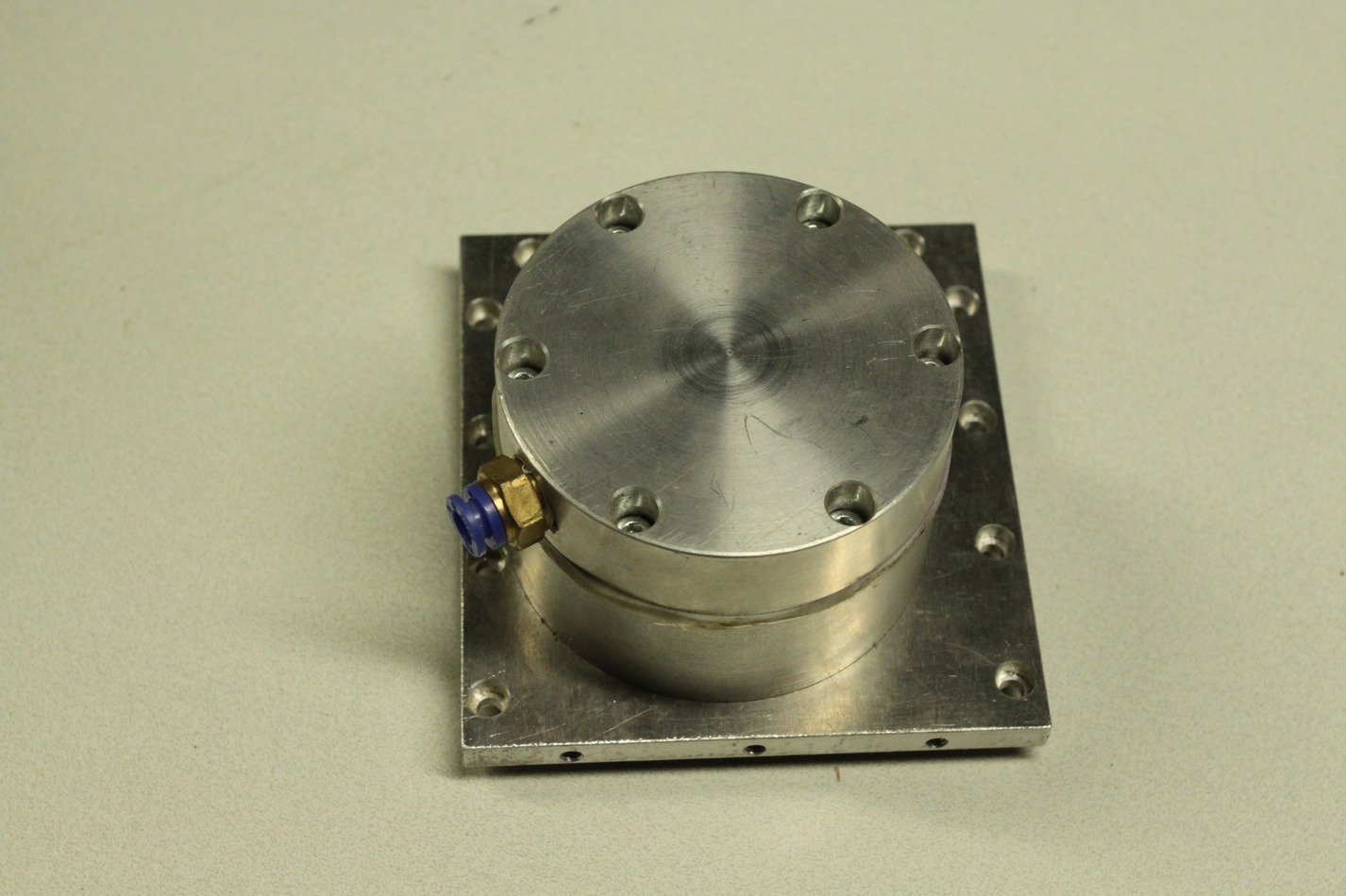
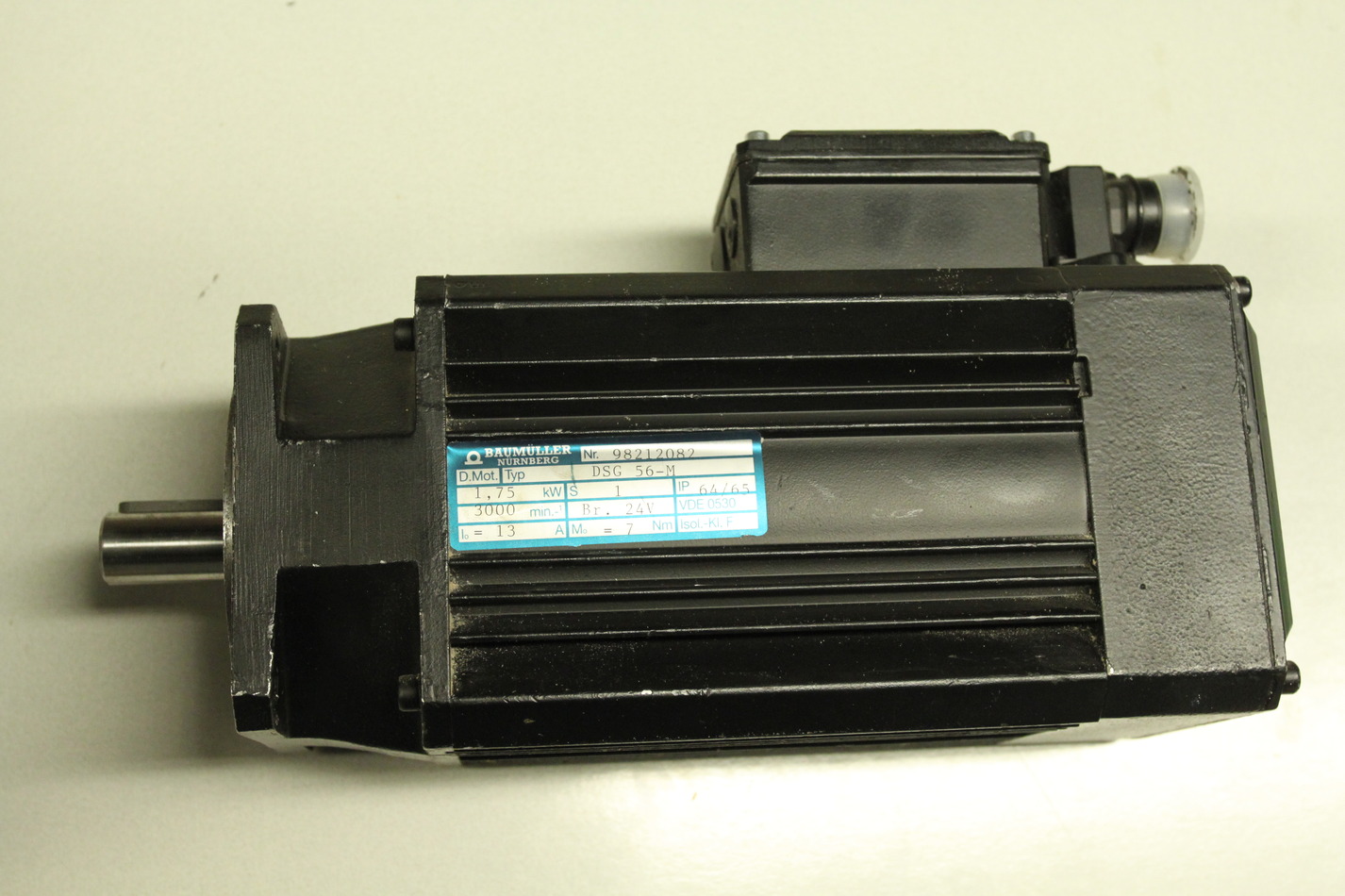
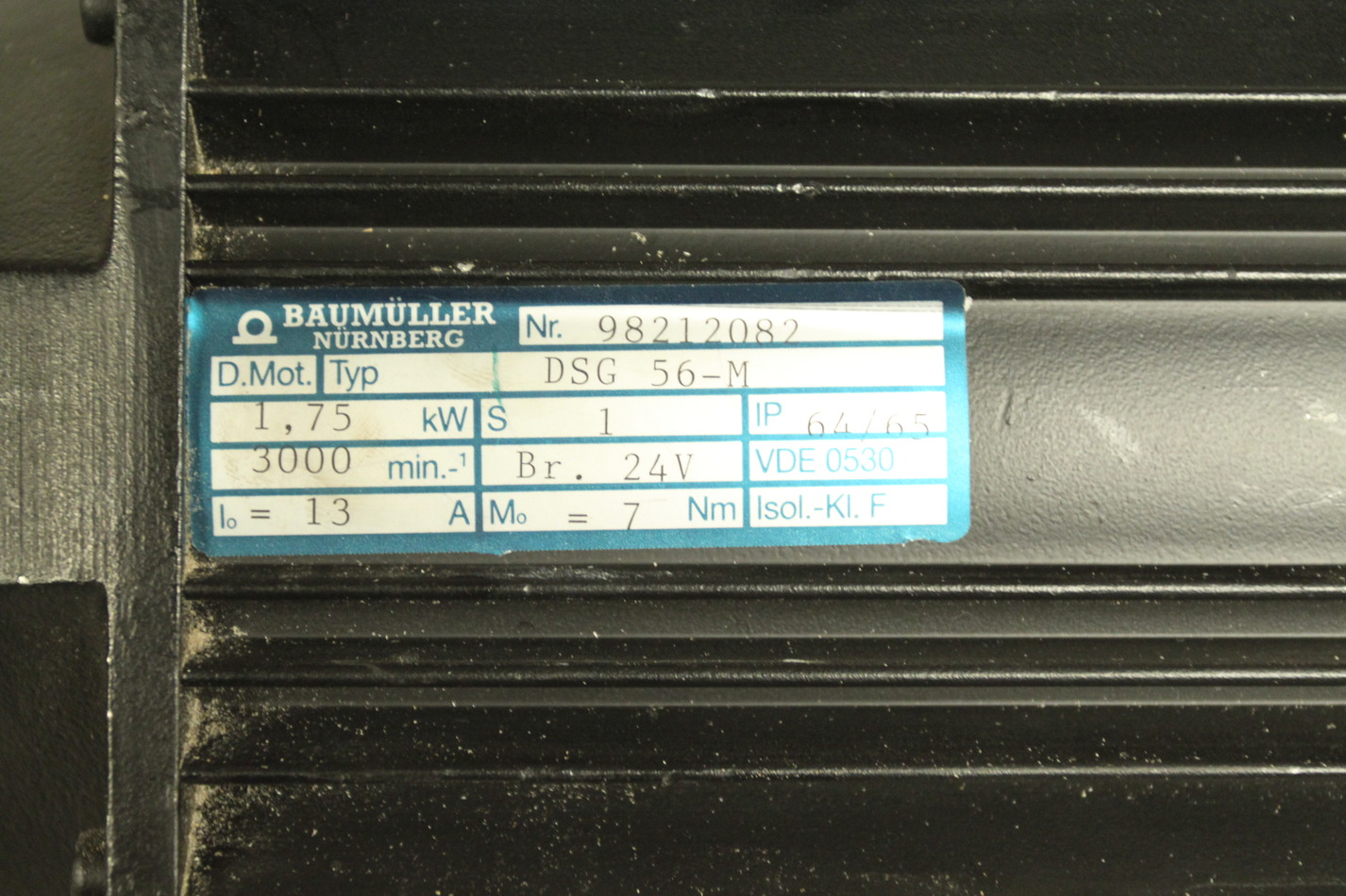
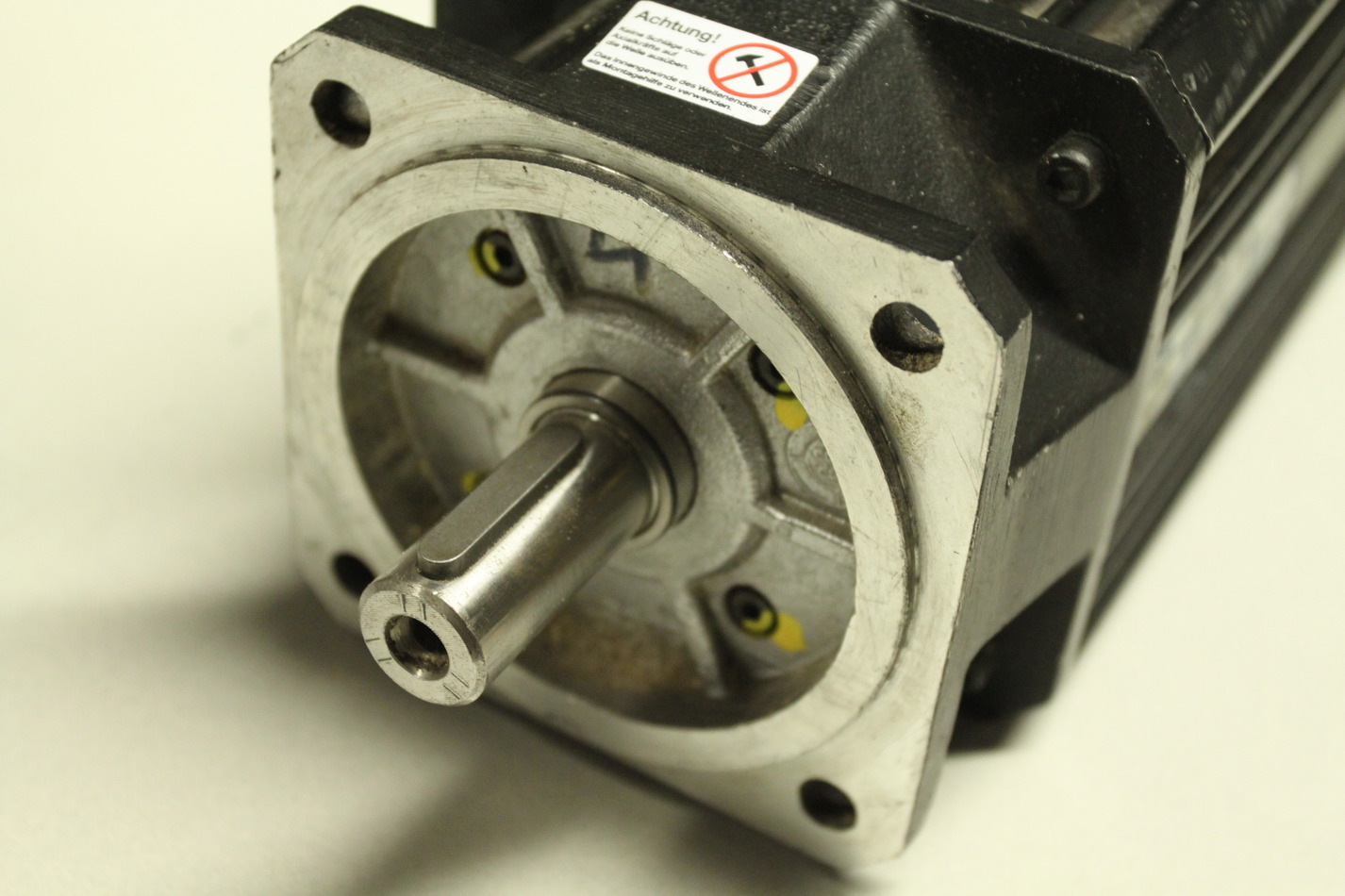
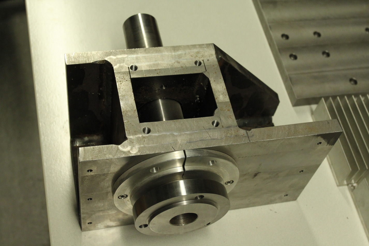
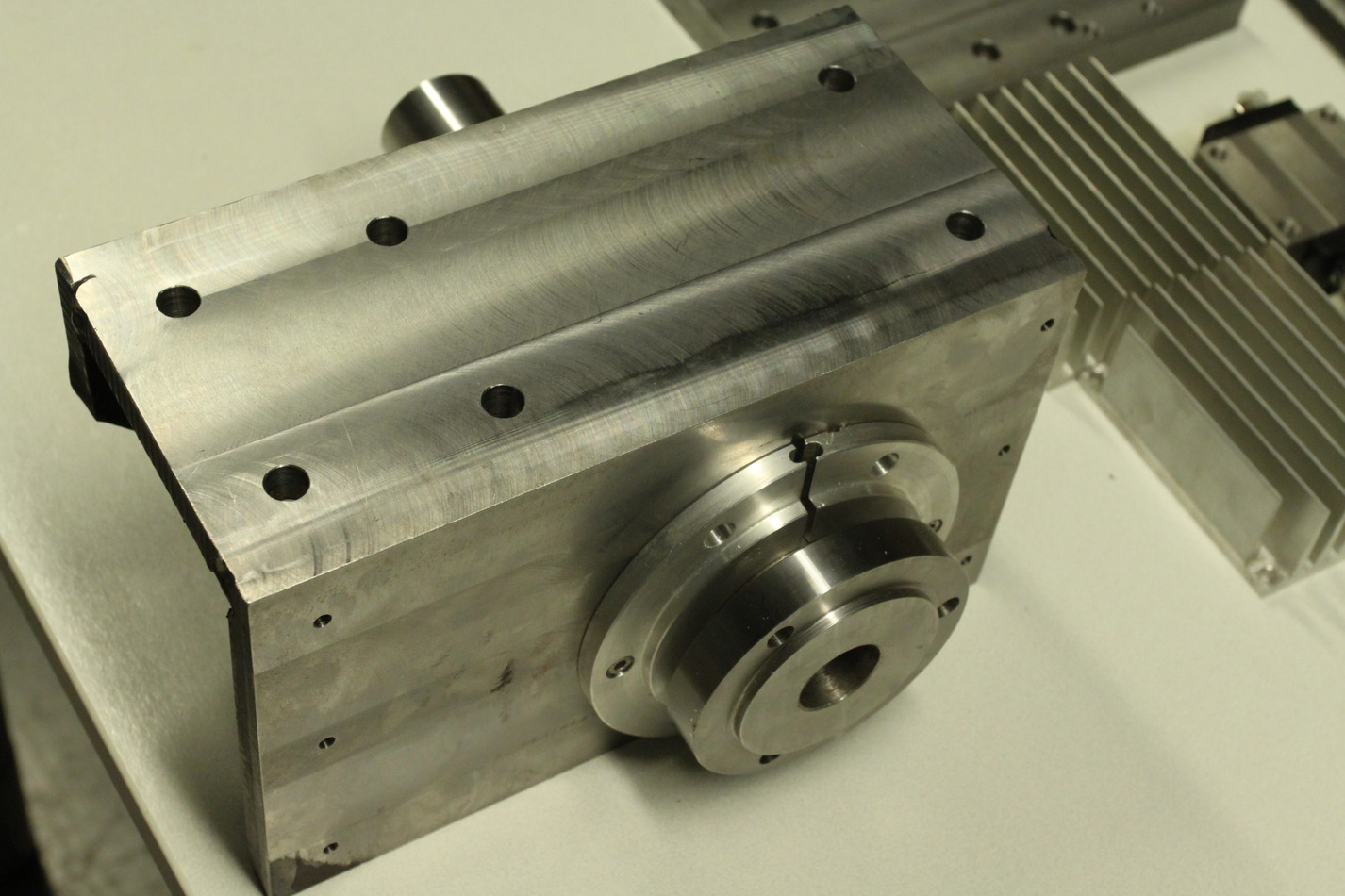
The spindle servo is rated at 1.75kW, 3000rpm, 13A, and 7Nm. The spindle servo axis is 19mm in diameter and ca 35mm long. The spindle itself is 45mm in outer diameter where the pulley for the belt-drive should attach. The chuck-holder is 100mm in diameter.
These images are also on picasa: http://picasaweb.google.fi/anders.e.e.wallin/JHQLathe2009_11_21#
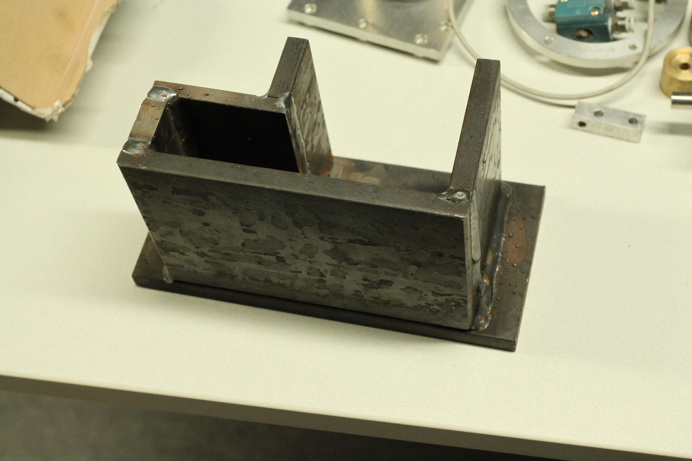
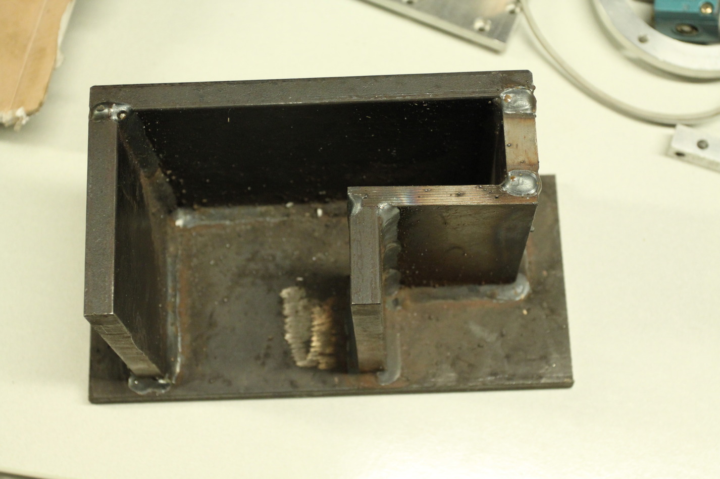
Milling Steel
And here some pocketing in aluminium:
MDF plug pictures
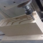
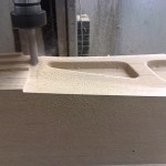
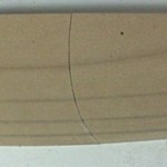

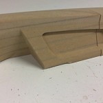
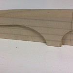
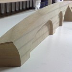
The first half of our Pikanto plug is now milled. The other half will be done next weekend - and then we have a lot of painting and sanding to do before laminating moulds.
Milling MDF
Servo setup with m5i20 and EMC2

By popular demand, a schematic which roughly shows the electrical connections of our cnc-mill setup. Most of it fits inside one box (also shown here). The m5i20 I/O connectors are on the left, followed by the optoisolator cards. E-stop chain in the middle, servo-amplifiers and motors to the right. Jog wheel at the bottom. The small VFD board I made later is not shown.
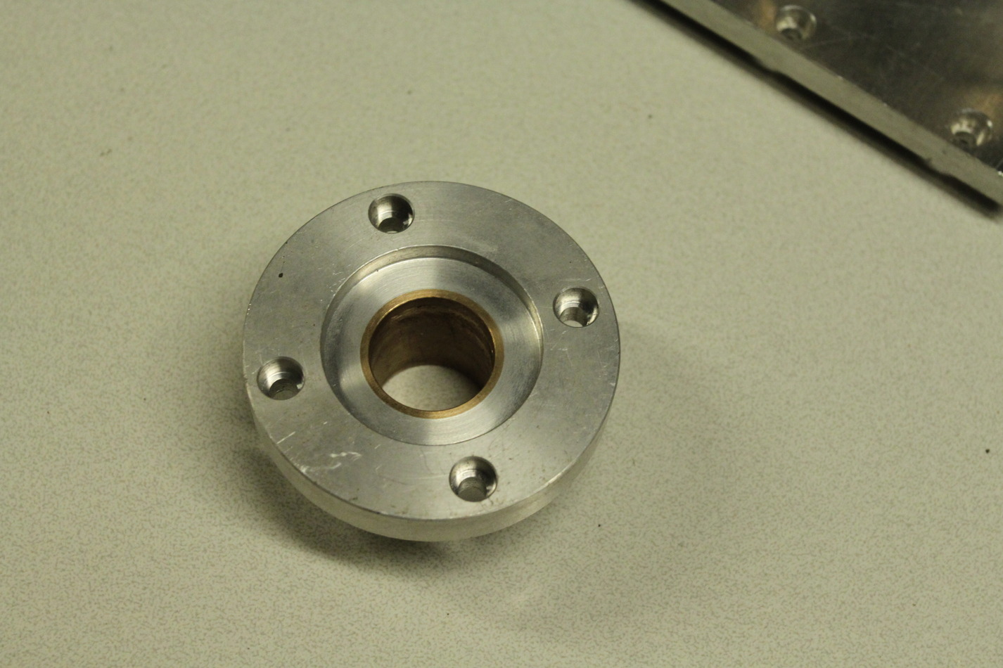
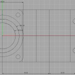
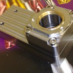
Nikon TE-2000 objective holder in steel

I'm fitting some more equipment around a Nikon TE-2000 microscope, and the stock objective turret is in the way. Machined this objective holder in steel yesterday.
Rigid Tapping
We've mounted a 500 cpr encoder on the spindle-motor which means it's possible to do rigid tapping. Above some spot-drilling, then a 2.5 mm drill, and then an M3 tap at 500 RPM and 0.5 mm Z-feed per revolution. Below the same thing but with a 5 mm drill and an M6 tap (1 mm Z-feed per rev).
Cool stuff!
Aluminium milling video
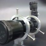
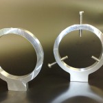
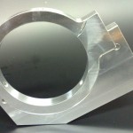
As promised, the video of the roughing + finish operation on the finderscope-ring drilling jig.
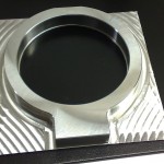
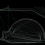
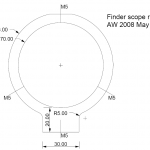
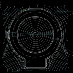
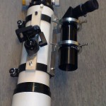
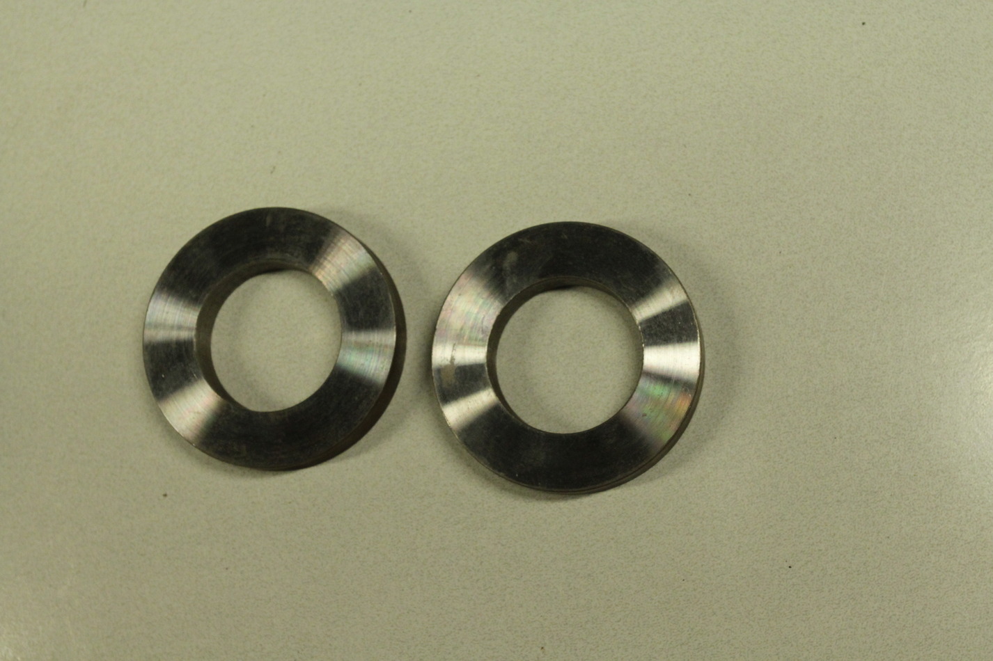
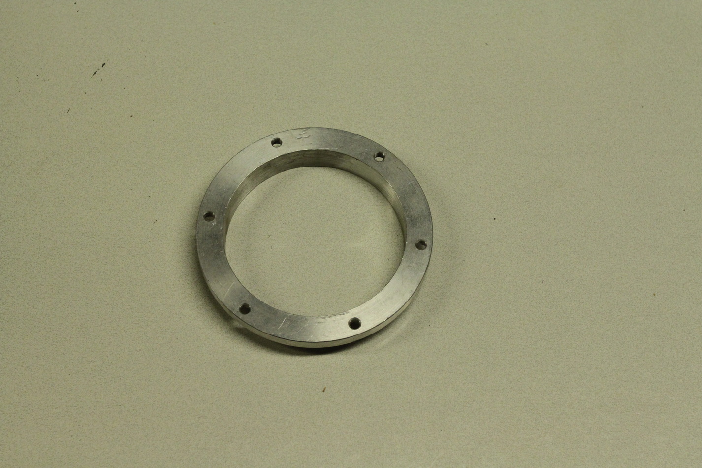
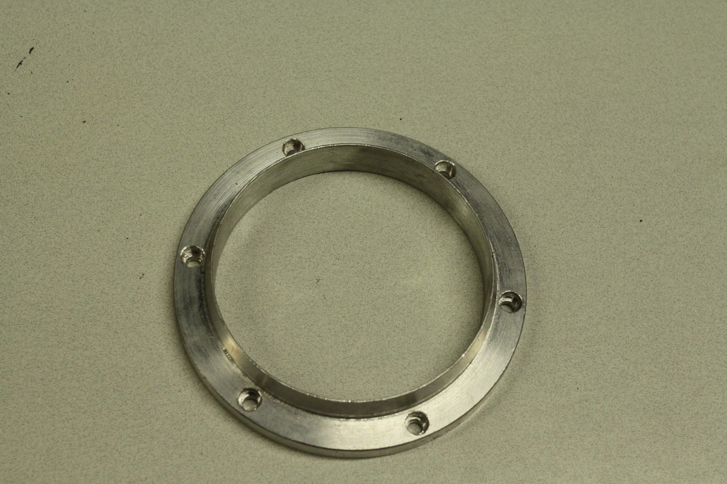
Finderscope rings

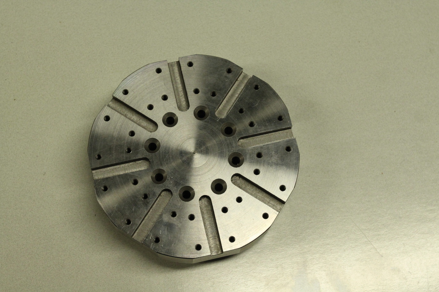
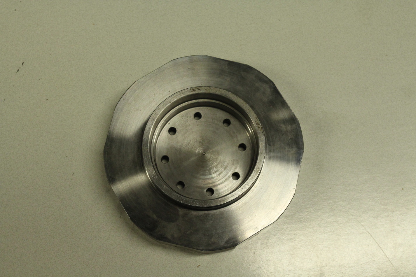
Last weekend we made some rings for mounting a finderscope on the main telescope. Today I got the holes drilled and tapped so the rings are ready to use. The gallery below shows the adaptive pocketing paths that were used to cut both the part and the jig that allowed drilling the holes at +/- 120 degrees.
There is a video of the roughing operation at 2000 mm/min that will be online soon.