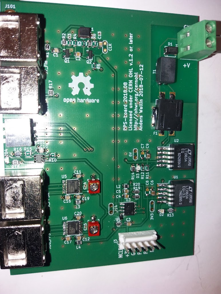
A second try at the PPS board, this time with the correct footprint for the transistors on the sine-to-square input stage.
Still some bugs left as I had to add a diode on the MCLR pin for the PIC-programmer to work correctly.
A second try at the PPS board, this time with the correct footprint for the transistors on the sine-to-square input stage.
Still some bugs left as I had to add a diode on the MCLR pin for the PIC-programmer to work correctly.