IOM sail camera videos

Looks like the mast bends to leeward at the middle, while the top of the mast stays in place. I don't think that's a good thing. Should try lower shroud attachment point and maybe shorter spreaders.

Remember to turn up the sound so you hear the wind, water, and the RMG winch! Also try these in higher quality by going to youtube and clicking "watch in high quality".

Here's how the camera looks on the foredeck:

IOM Sail Camera

Jari got a Hero camera which takes still pictures and video and stores them on a memory card. It weighs about 120g and it's watertight, so it's possible to put it on-board and take some pictures while sailing. Seems to work quite well. This could be used later for looking at how the mast bends in different winds and with different shroud and/or spreader positions. (See here for some statistics from the ongoing IOM Euros).

KLV IOM ranking race

10 boats, including two guest sailors from Russia with Naviga one-metres, completed 12 races in varying no1 rig conditions.

The pictures show some cnc-milled aluminium fittings by Jari Immanen, and Oleg Konka's RUS-32, a Naviga one-metre built by Janus Walicki. Note the rudder. The forward section has an airfoil shape while the aft half of the rudder is a very thin and flexible carbon sheet.

Bulbs of Steel

As a first serious test-run for our now servo-controlled cnc mill we decided to make an IOM bulb out of steel. It ends up a bit bigger in volume when made out of steel compared to lead, but the difference isn't huge. Making it with a cnc mill allows designing almost any reasonable 3D shape you can imagine.

The mill worked fine during the whole run, about 3 hours of rough-cutting and 1.5 hours of finish cutting, but there was a slight operator error in the setup which means this bulb will likely not sail. The following error stayed low throughout the run, and the servos weren't even hot to the touch after the workout.

We used adaptive roughing paths and then a simple parallel finish path. Both operations are cut with an 8 mm flat cutter. The adaptive paths did seem to work, and on this size machine they are really handy since a slight over-cut will likely stall the spindle motor (1.5 kW and 5000 rpm, small by big-iron cnc-standards).

0:00 rough cutting begins. The stock is a 45 mm diameter steel bar, face-milled down on the sides so it can be clamped to the machine vises. Note the cutting feedrate which is 500mm/min and 'high-feed' in the (x,y)-plane when the tool is positioned for the next cut. When the tool lifts up to the clearance plane it does normal G0 (rapid) moves.
1:34 more rough cutting on the other end of the bulb.
1:58 still pics of the rough-pass almost ready
2:15 view of emc2 while cutting. Note pyVCP bar widgets showing commanded PWM to servo motors.
4:29 beginning of parallel finish cut. programmed feed 1500 mm/min which is attained briefly in the middle of the move.
5:00 more finish cutting, about 2/3 done.
5:50 another view of emc2 and the pyVCP panel. Note Y and Z motors working to position the tool. The following error for each axis is also shown.
6:15 still pictures of the finished bulb (well, one half of it anyway). Note at the front of the bulb we tried to run the program at 150% of programmed feedrate, but that didn't work at all and resulted in a poor surface finish. We did try to slow down also from 100% but that didn't improve the surface much.

Google video doesn't really do justice to the nice 640x480 video and 5 Mpix still-photos that come out of the N95, so if you've bothered to read this far, here's the original 100 Mb mp4 (I hope I don't exceed my bandwidth limit).

Widgets for Sail

Graham Elliot from the UK doesn't have a website of his own (yet?) , but wanted to let everyone know that he is now building and selling the Widget IOM. Designed by Chris Dicks in 1995 the boat has gone through quite a few changes to everything except the hull shape. The Widget has won the 1996 European Championship, the British National championships in 1997 and 2007, and the 2007 World Championship, not bad for a boat that was designed 13 years ago. The mouldings of the boat are manufactured by Dave Creed.

Graham's options and prices are:

  • Boat complete to deck level, including cf fin and rudder, all attachment points, pulleys, adjustable main post, keel, all finished = 840 euro.
  • RMG 280D, 42mm drum, thumbscrew, fitted in boat=215 euro.
  • Rudder Servo, hitec 645 ultra torque, fitted in boat=75 euro.
  • Rigs: prices vary depending on which fittings (sails etc or housemartin) and also which sails are preferred (housemartin , Brad Gibson , Stealth , sails etc)
  • Wooden rig box= 80 euro
  • 4 colours: red, orange, blue, grey. They are all sprayed using Epifanes 2 pot polyurethane paint.

Currently (Feb 2008) there is a waiting list of approximately 16-18 weeks.

Please contact Graham Elliot on elliottyachts "at" hotmail.co.uk if you are interested!

Sepktrum DX6i, HiTec HSR-5990

Spektrum recently introduced an updated version of the DX6: the DX6i. Horizon Hobby also has an article on the new radio.

This one uses 'DSM2' technology which is described as giving 'full range'. Not sure what that means, but range should be better than with the first generation of 2.4 GHz radios, which at times was problematic (if you did something specific that cut down on the range).

I think the original DX6 was more or less a carbon copy of an existing JR transmitter, but the DX6i seems to be a new ergonomic design. Instead of buttons for navigating the menu it has a roller-device, and there's a new bigger LCD for programming.

The antenna still sticks out at the top even though nobody has had a mobile phone with an external antenna in years. I've mounted the antenna on my own DX6 inside the plastic case and it seems to work fine. I predict and hope that the next version in 1-2 years from spektrum will have the antenna mounted inside the Tx (no fear of breaking it, no problems with leaking rain-covers).

It's going to be in stores in December, for around $180 without servos, which is similar to what the 6-channel 2.4 GHz Futaba sells for.

HiTec has replaced their previous robot servo (HSR-5995, now discontinued) with a new version called HSR-5990. The specifications are roughly the same as for the old model: torque is 24.0 or 30.0 kg.cm depending on if you use a 6 V or 7.4 V battery, but speed is down a bit from 0.15s/60deg to 0.17s/60deg (6 V). The gears are Titanium alloy, and as is visible from the picture the new servo adds a heat-sink to the casing.

Maybe this is the winch for my next boat? At a cost around $110, weight of 68 grams, and 'ludicrous speed', it looks like a strong alternative to a drum-winch. Anyone have good or bad experiences with the 5995 or the new 5990?

More Marseilles pics

Here's David Potter's GBR20 Lintel. Note how high the gooseneck is. The boat is not so fast in light weather, so this is an attempt to get the rig higher up and gain some speed in the light stuff. Home-made gooseneck with laser-cut stainless steel bearing holders at the top and bottom (note adjustable holder at the bottom), and a carbon swivelling part. David also has the auto-adjusting cunningham arrangement with the line threaded around the mast. It's not very visible from this picture, but the mast-ram is attached to the mast - so there are three mast rams that stay with each rig, and the correct adjustment stays with the rig. Gelcoat on foredeck has been left out to save weight.

laser-cut ss spreaders. They look nice and work well but are not detachable for transport like the normal ones. They rotate to be parallel to the sail, but still stick out a bit more than normal spreaders do.

laser cut hooks for jib and toppinglift, and below that a separate hook for the shrouds. Note how low the jib attaches compared to the middle measurement band - that's because the mast and mainsail are higher up due to the high gooseneck. Rake adjustment with multiple holes in the mast.

Laser cut ss mast crane.

A box full of laser-cut parts.

Pierre gonnet had some fittings on display.

Gooseneck fittings.

some black bottlescrews for shroud tensioning.

Finally a few pictures of Brad's boat.

no1 rig jib attached to the deck with a piece of string through the deck eye. An alternative to the through-deck tube which is more elaborate to build.

A view of the rig. Shrouds attached to the same kind of hook (covered with tape) on the front side of the mast as on GBR20, but much lower on this boat.

IOM details from Marseilles

Here are some detail pictures from last week that I thought were interesting.


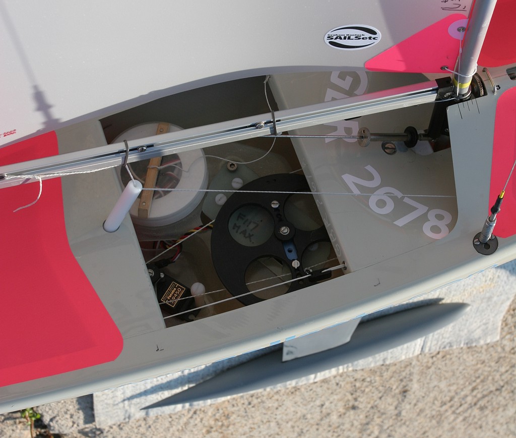
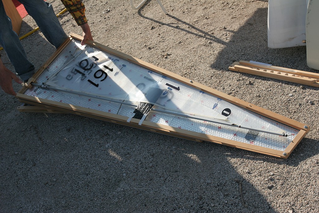
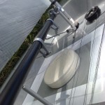
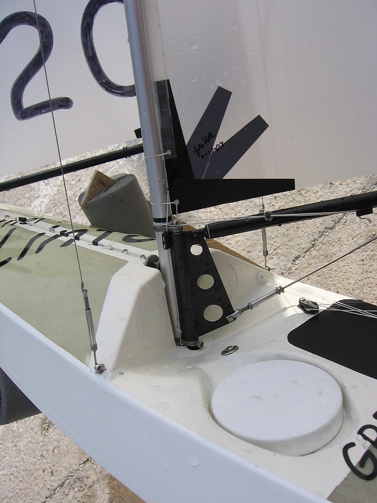
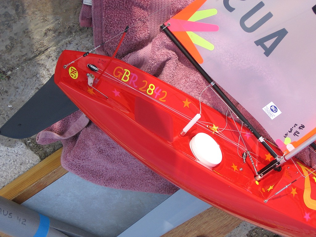
Graham Bantock's Topiko. Note quick-release bottlescrew and deck-fitting far right. Also note how the cunningham is threaded through a plate with holes around the mast. I think this gives a variable cunningham tension (tight on the beat, looser on the run?)


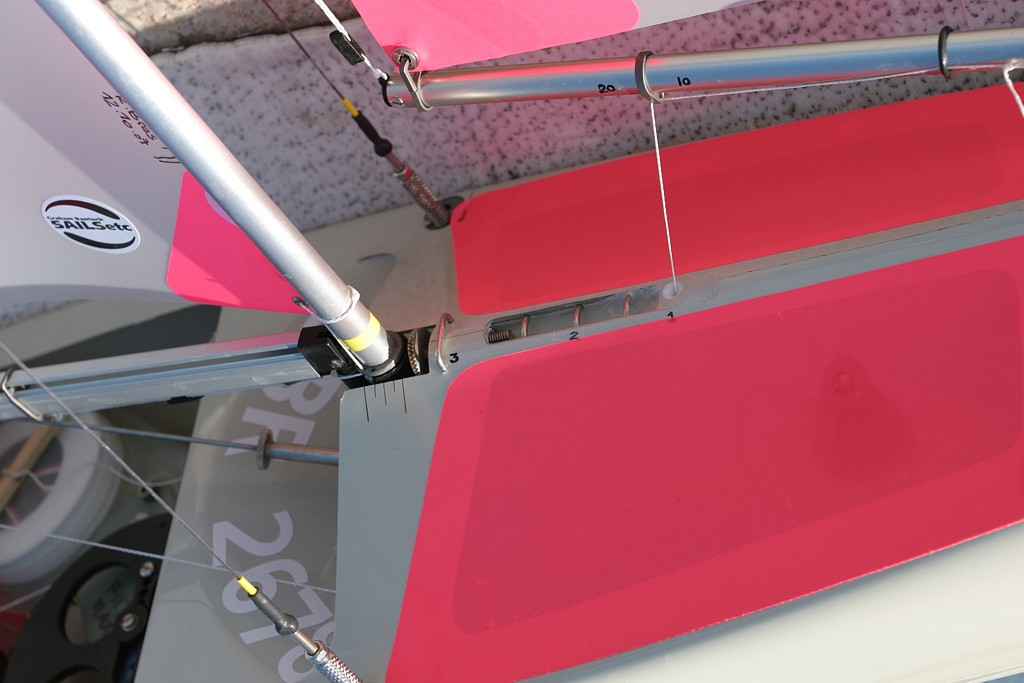
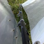
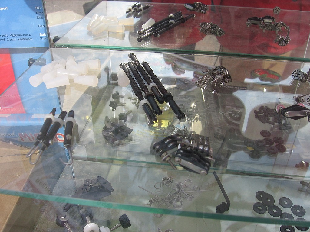
Recessed jib-sheeting hooks. With the new sheeting system and the arm-winch configuration there's no endless-loop or other sheeting lines on the deck. Just the jib sheet very neatly coming out of a PTFE fitting in the foredeck. Many boats do not use a separate sheeting position for the no2 and no3 rigs, so I guess threading the sheet under the metal wires for the no2 and no3 rigs is optional.


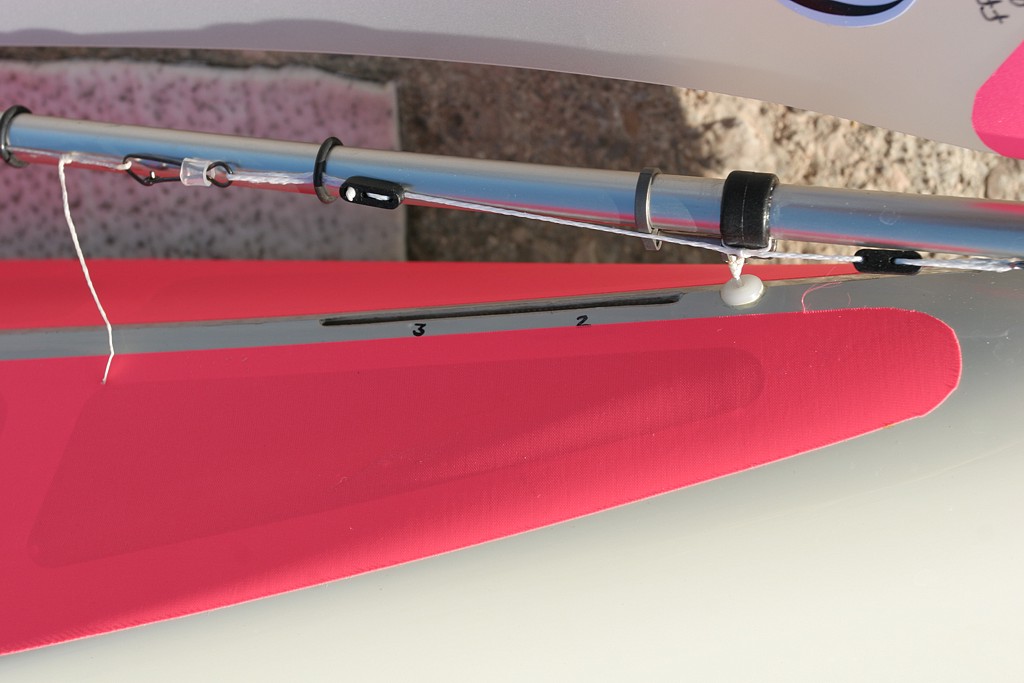
Same kind of recessed wire-hooks for no2 and n3 rigs. The no1 rig uses a piece of Dyneema that attaches to the bottom of the boat and comes up on foredeck through a tube. I wonder if the added complexity for building this is worth it? Sheeting angle adjustable with a bowsie.


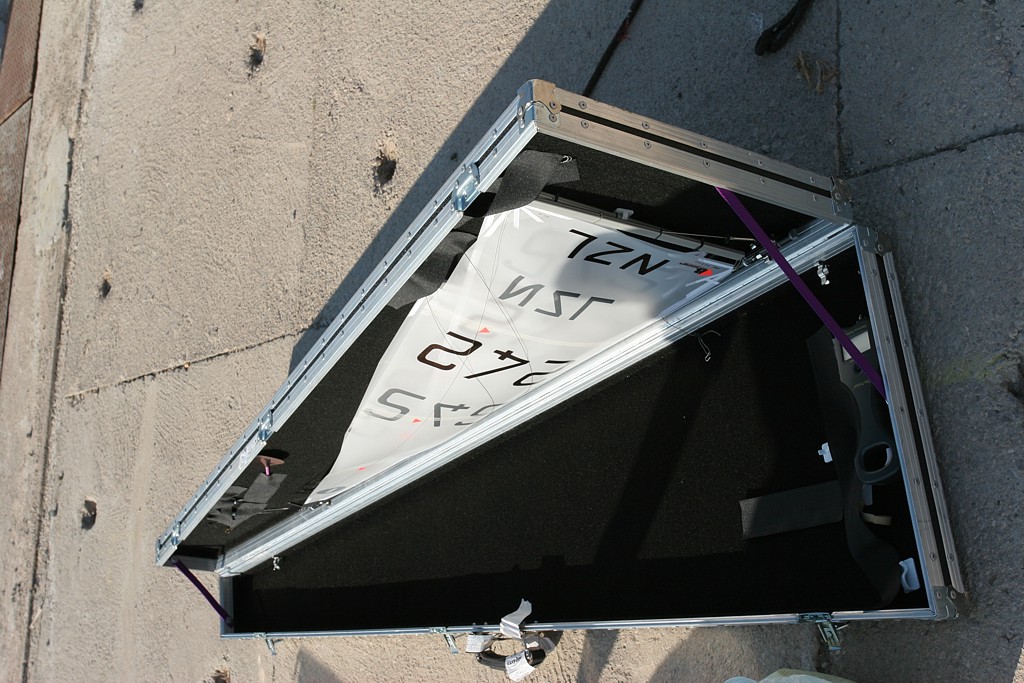
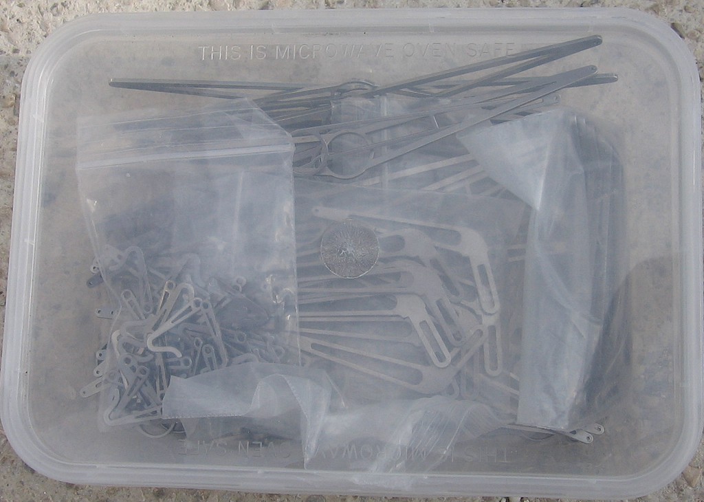
John McPherson's very serious looking rigbox. My own is similar but this one is deeper so could probably fit two sets of rigs.


A Gearman, breathing version of a rigbox.

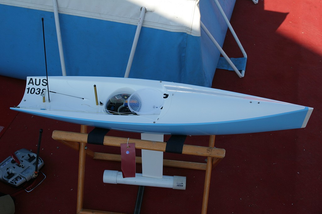
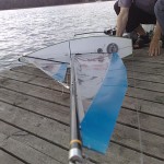
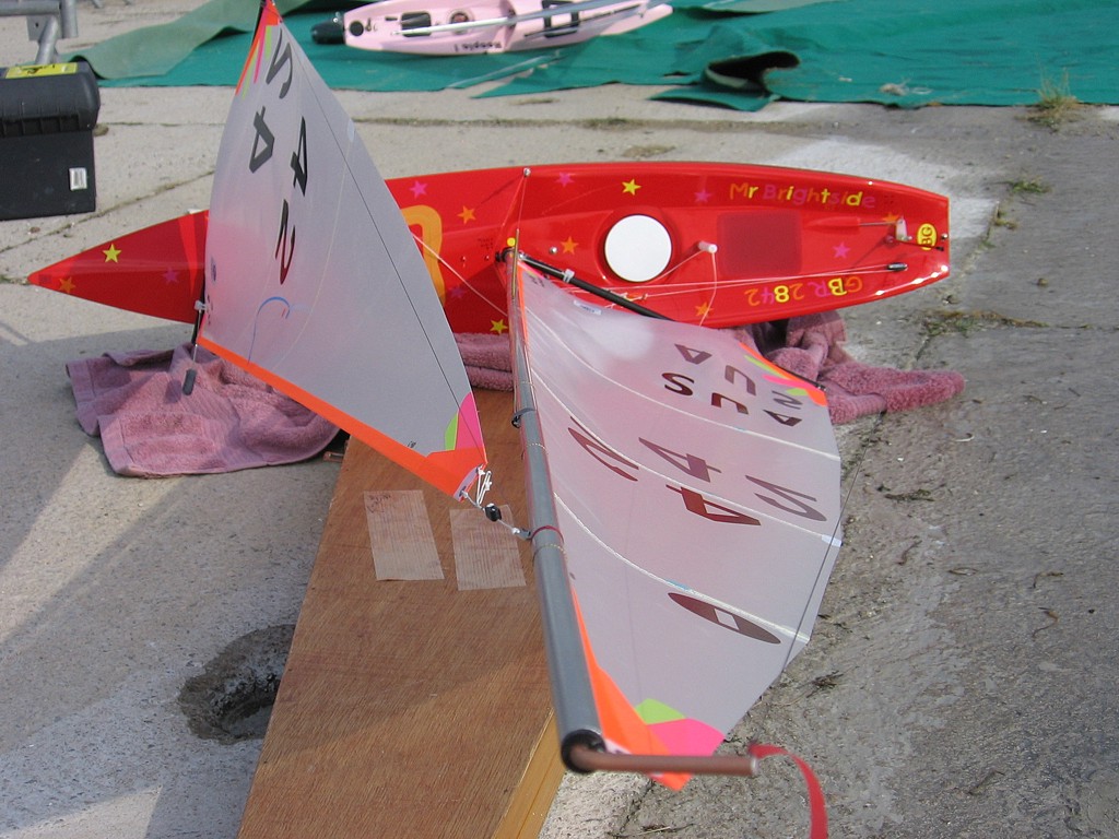
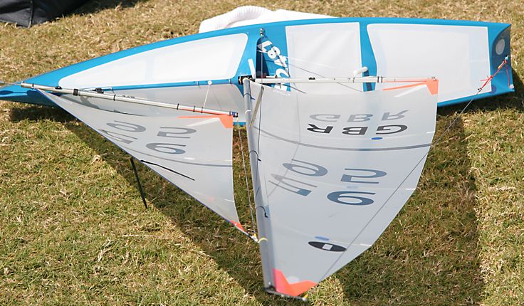
Craig Smith sailed the same Obsession prototype that he won with in Mooloolaba, and Simon Kellet's Obsession boat pictured here is the first (and so far the only!) production boat.


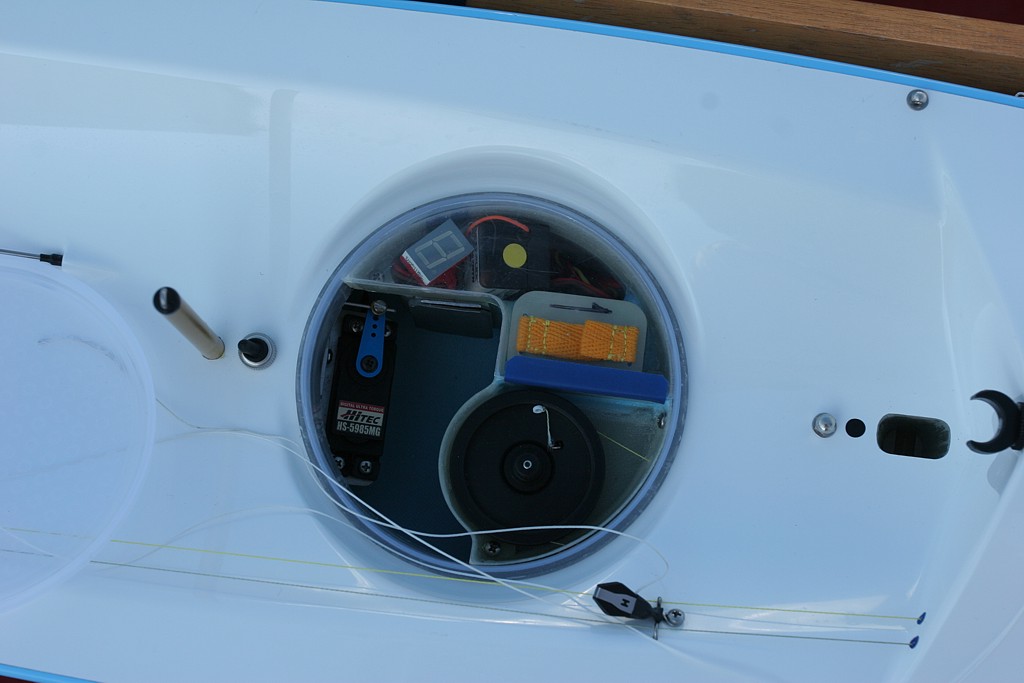
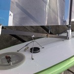
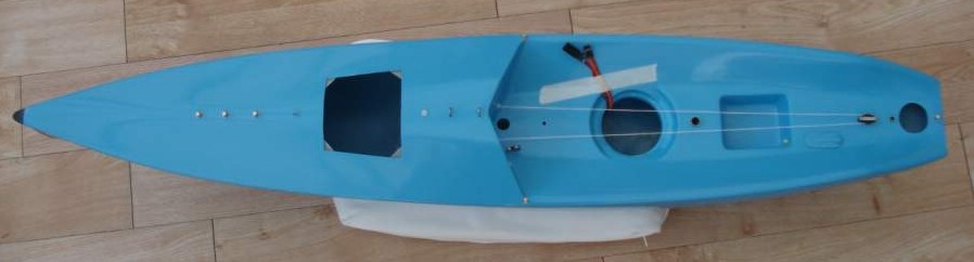
The round Decor hatch with all the radio installations neatly in one place. The battery even has connectors on the bottom of the fibreglass casing - just press it down and it connects.


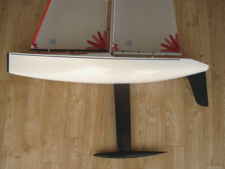
Note how much the rudder tube leans forward. I wonder what this does to the function of the rudder. Any boat designers want to comment below?


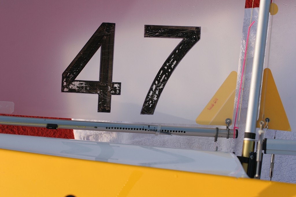
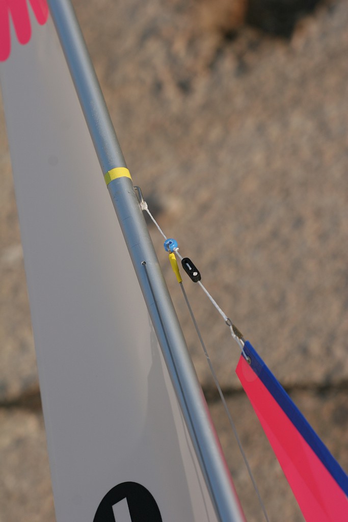
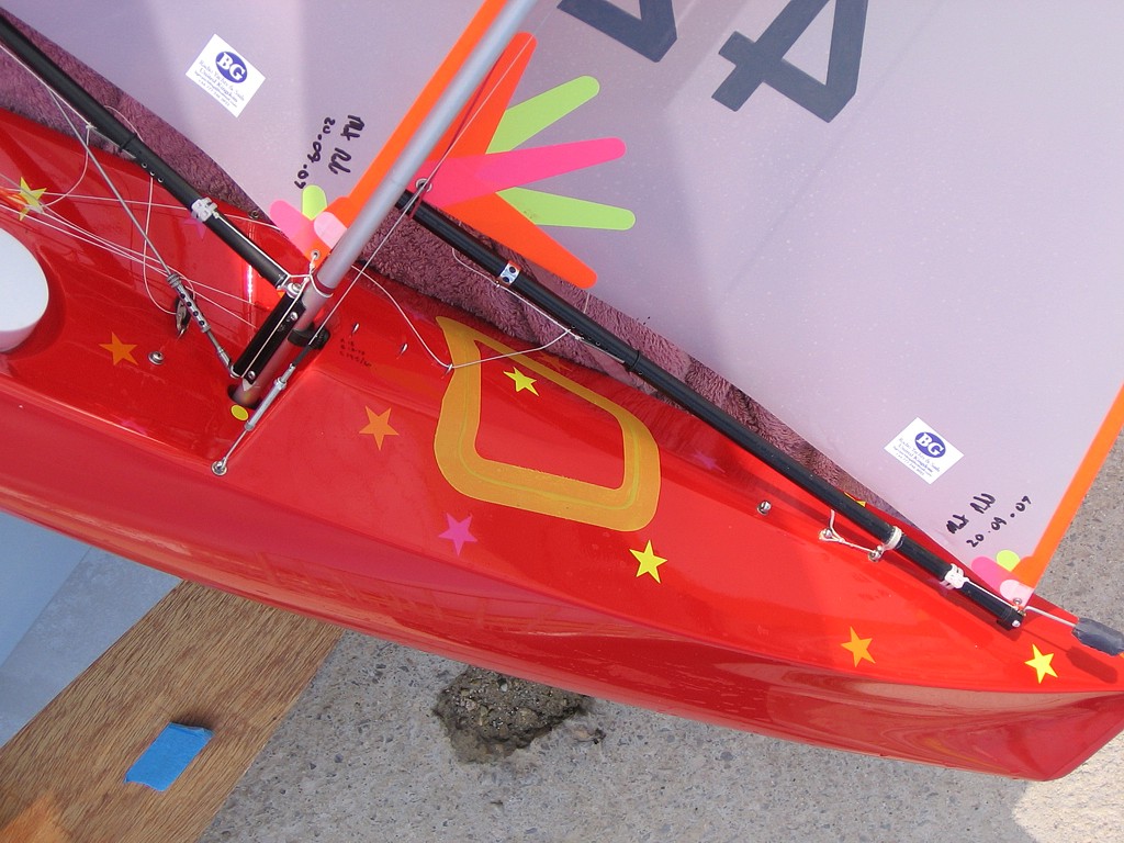
Craig Smith's no1 rig jib. Note how the topping lift bowsie is to the left in the picture and the topping lift is threaded inside the boom and comes out at the end. The pink elastic keeps the topping lift tight so it doesn't catch the spreaders. There's only one sheeting eye in the deck that is used with all three rigs. Similar to GBR-95, the cunningham is threaded around the mast to give an auto-adjusting effect. Lester Gilbert has two interesting notes on auto-adjusting cunninghams here and here.


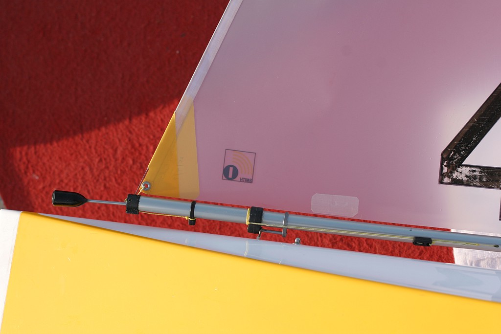
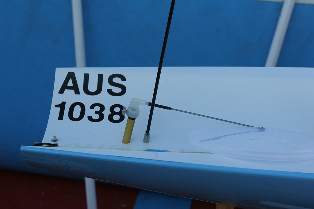
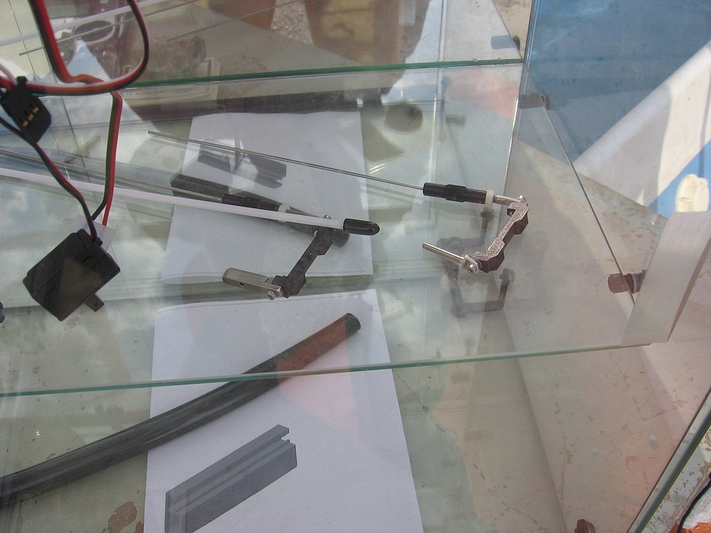
Forward end of Craig Smith's no1 jib. Craig is also using the Dyneema thread idea for the no1 rig jib swivel. Although putting in the tube is one more job when building the boat you do get a useful stiffening of the foredeck at the same time. Craig seems to use the same deck-eye for both the no2 and no3 rigs as there is only one attachment point aft of the no1-rig swivel.


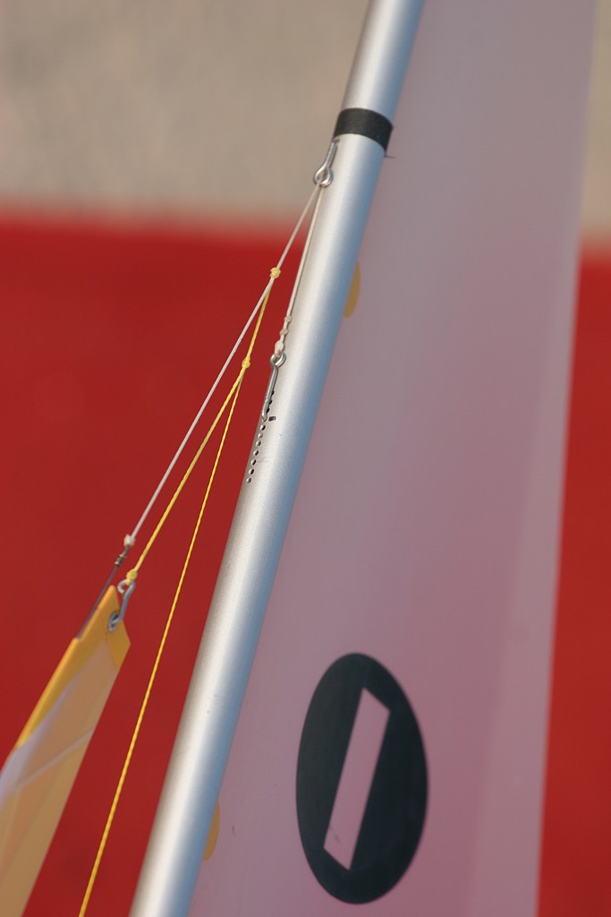
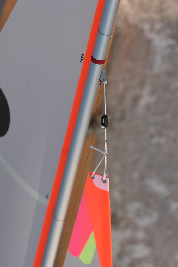
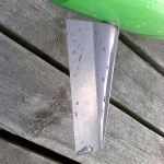
Craig's very neat and minimal top jib attachment. The overall rake of the mast can be adjusted by moving the hook up and down on the mast. Note how the topping lift and the jib attach to the jibstay. There's no shroud attachment point in sight in this picture (compare that to pictures below) - which means Craig uses a much lower attachment point than Graham.

I'd love it if someone took measurements and wrote them up like I did in 2003.


Graham's boat again with another view of the new quick-release bottlescrew. Note that Graham doesn't use adjustable sheeting attachments any more. I think it's because the arm-winch is significantly more precise than a drum winch, so there is not much variability from day to day or month to month in how far the sails come in when you set up the boat.


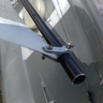
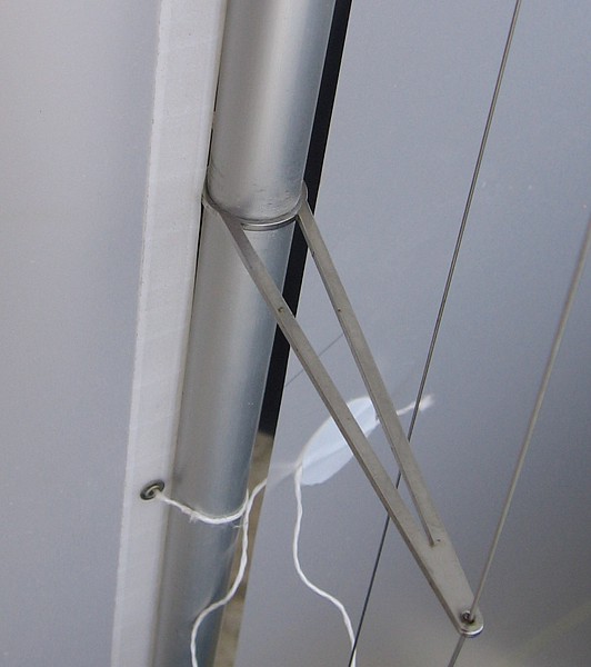
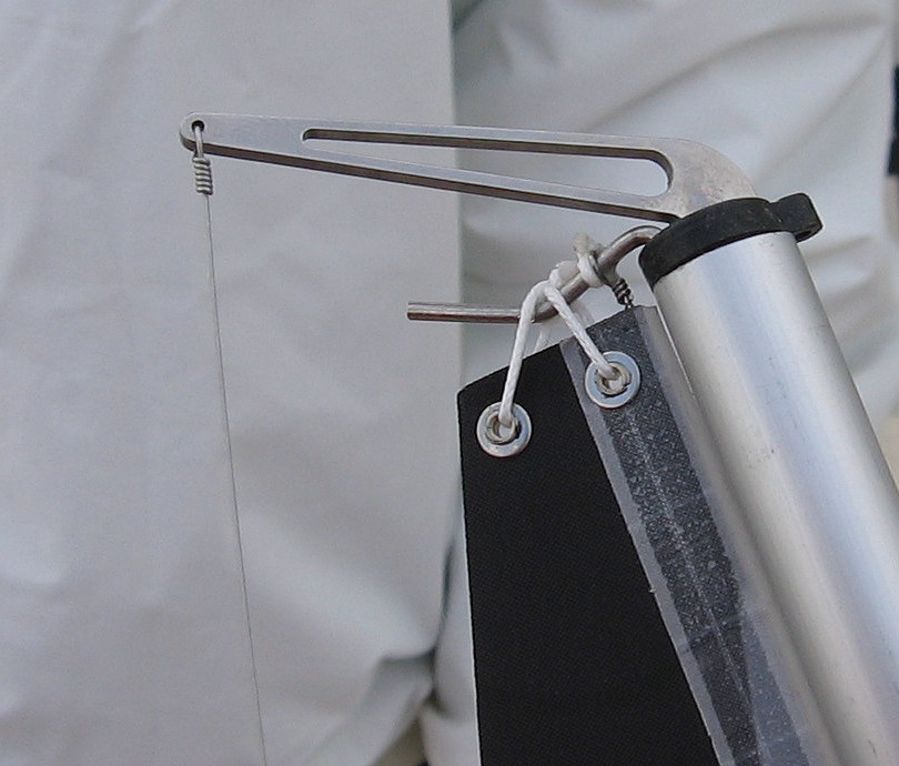
Graham's top jib attachment with a bowsie for controlling mast rake. Note use of the flat steel tape for the topping lift. The same steel tape is used for the shrouds, which attach just below the jib-attachment point. Compare this to Graham's Mooloolaba boat where the shrouds both attached to the same point on the front side of the mast. (more from Mooloolaba here)


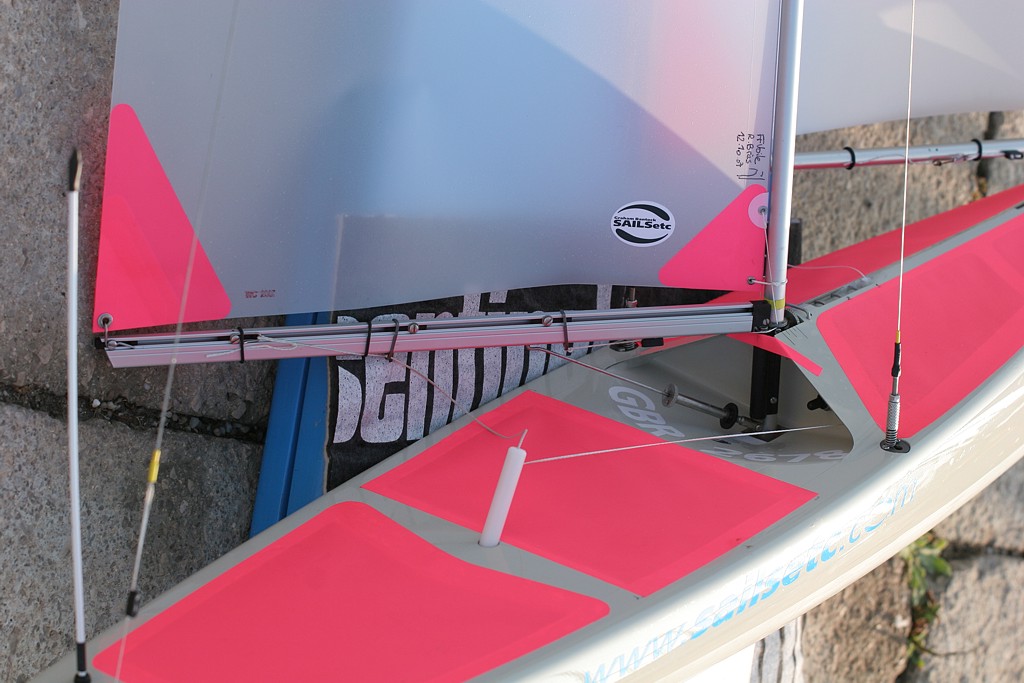
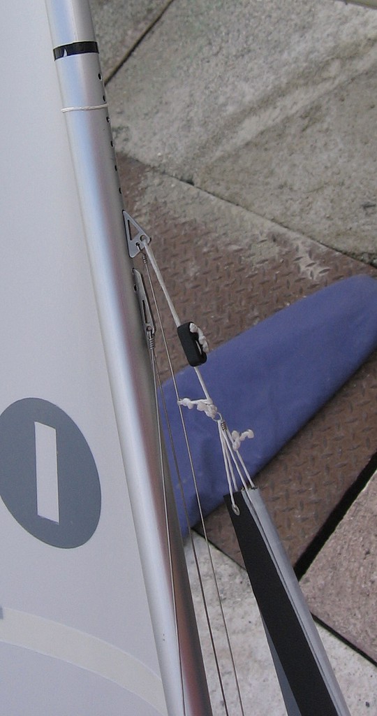
Brad Gibson's no1 rig jib with a nice cnc-laser-cut steel hook for the jibstay and the toppinglift, and a piece of string pulling the topping-lift forward and clear of the spreaders. Again no shroud attachment point in sight - which must mean that Brad uses a similar low-shrouds configuration as Craig.

I have some more of these which I'm hoping to get online soon, in particular some pictures of the Lintel and more cnc-laser-cut fittings from David Potter.

If anyone has some pictures that they think would be a good addition please feel free to comment below or email me directly!

KISS IOM Construction

(click image for high-resolution version)

The current Noux Mk2 construction is obviously too difficult to put together. There are lots of separate mouldings that need to be fit and bonded to the hull, lot's of sanding, filling, and painting. So I'm trying to think of a simpler design that would be easier to build. With all the moulds and jigs ready my dream would be to spend one whole day on moulding: hull, deck, fin, rudder, etc. Go home and sleep/do other things while everything cures for a day or two, and then spend the next day bonding together the components. With about two full days of work I would hope to create a ~500 eur kit which can be handed to an intermediate to advanced IOM-skipper which he/she could then complete by adding fittings, radio, and rigs. Is this Utopia?

The Bantock/SailsETC style of construction (Topiko-ish drawing above) simplifies building somewhat. The two halves of the hull (1,2) are moulded separately and then joined. A separate fin/mastbox laminate (3) needs to be bonded into place while the hull is in a jig, to keep everything nice and straight. The foredeck comes 'for free' in the hull moulding process, but the aft deck (4) is a separate moulding. Here I've drawn a recessed flat part for mounting the winch and the servo, and a place for the 65mm RC-pot aft of the main-sheet post.

Then there are small bits and pieces like the rudder tube (5), the tube for the no1 rig (6), and the bow bumper (7).

Sails ETC sells a cheap plastic rudder (R), and some not-so-cheap fins (F). We can make bulbs (B) in lead by casting, or maybe in brass or steel by cnc-turning in the future.

I really feel the challenge is in components 1 through 4, the large mouldings that need to be accurately assembled, and apart from the finbox need to have a nice gelcoat outer finish. With the Topiko-style transom the two hull-halves (1,2) can't be assembled in the hull mould, so a separate hull mould without the inverted transom is needed. This assembly-mould/jig could also have a permanent hole for a dummy-fin that is put in place and aligns the separately moulded fin/mastbox (3). The aft-deck (4) would then be bonded in place with the help of strips of glassfiber plate glued to the underside of the hull-flange.

If I count the building tasks correctly I get something like this:

  1. Mould two hull-halves. (spray mould with gelcoat/paint, apply epoxy+2x125g glassfiber, trim glassfiber to mould-edge)
  2. Mould other components: deck, fin/mastbox, mainsheet-tube, no1-rig-tube, bumper (in silicone)
  3. Wait for everything to cure
  4. Assemble hull-halves in separate jig. bond together. Glue in fin/mastbox, Glue in deck (can this be done simultaneously with finbox?). Glue in rudder tube.
  5. Wait for everything to cure
  6. Finish by adding bits and pieces: open foredeck holes, glue in no1-rig tube, glue in mainsheet-post tube, attach bumper.

That's three tasks separated by curing-time. I'd be interested if anyone has some thoughts on this! Have I overlooked something big? Can this be simplified further?

I know some people have used closed-mould techniques with a pressurized balloon inside to mould complete boats in one go. But as there are no good descriptions of this online I'm not going to pursue that in the near future.