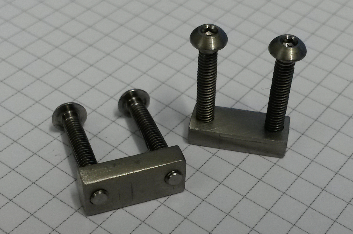
I made these two plate-nuts on the manual mill today. 3mm thick Titanium (ASTM B265 - grade 2) sheet from Titanium Service. The plate-nuts measure 12 x 5 x 3 mm with 9 mm center-to-center for the M2.5 threads. The M2.5 screws are also Titanium - since we don't want to use magnetic materials for these parts.
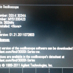
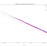
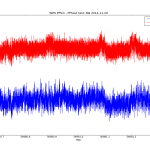
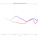
We got some White Rabbit Switches and I did an initial test of the pulse-per-second (PPS) output stability. In contrast to earlier measurements that showed 200ps or so of white phase noise, the PPS output on the WRS now seems a lot more stable. For various reasons the noise-floor (red data) of our 53230A time-interval-counter is at around 50e-12 @ 1s, and the WRS PPS output is at very much the same level of stability. Another 53230A counter shows about 13 ps standard-deviation for a cable-delay measurement - so I may redo these measurements with that counter. In any case a real evaluation of the short-term stability requires a DMTD measurement at 10 MHz.
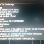
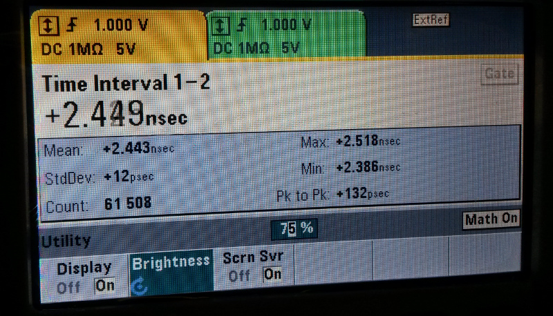
Update: after the fix the counter seems OK again. 12 ps standard deviation (61k PPS-pulses, collected over 17 hours) on a cable-delay test:
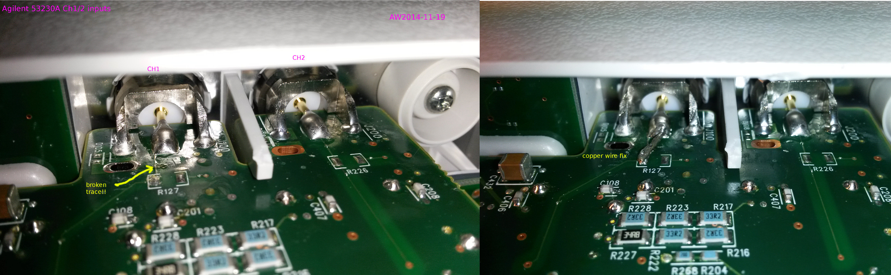
A broken CH1 input trace seems to be a common problem on the Agilent/Keysight 53230A counter. This is the second unit with the same problem we have seen.
The fix is to bypass the broken trace with a wire directly from the center of the input-BNC to the next unpopulated SMD-pad.
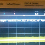
Here's the beat-note, as seen on a spectrum analyzer, between a red laser at 445 THz (or 674 nm, if you prefer wavelengths instead of frequencies) and a femtosecond frequency comb. The frequency comb has evenly spaced (100 MHz in our case) 'teeth' at well-defined multiples of RF-frequencies that we can lock to a H-maser. This allows absolute frequency measurements of the optical frequency at 445 THz. Currently we are trying to improve the SNR of the beat-note so that a frequency-counter will give a stable output reading of the beat-note frequency. The video shows about 20 dB of SNR using 10 kHz RBW (if you are optmistic), but reliable counting requires around 25 dB SNR using a 100 kHz RBW.
Viikin vitonen 5k race today. +2C and a bit windy. 22:52 or 4:33/km. 1km splits: 4:26-4:30-4:31-4:39-4:37. Maybe slightly too fast in the beginning which made the 4th and 5th kilometre hard.
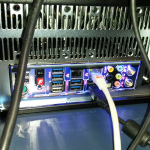
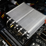
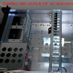
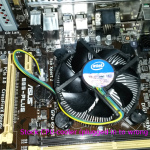
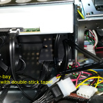
Another rack-PC put together this week. Intel X99-chipset with LGA2011-3 CPU socket. Only PCI-e slots, no legacy PCI-slots.
Again I didn't get the polarity of the HDD-LED and Power-LED wires right on the first try. How come the industry cannot agree on a standard connector for the bundle that has the power-switch, reset-switch, HDD-LED, and Power-LED?
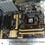
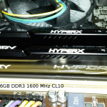
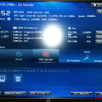
Another glitch was that this board has 8 slots for RAM, and the two RAM-sticks I got need to be installed exactly in the right slots - otherwise it won't even boot into the BIOS. Some reading of the motherboard manual was required.
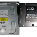
After installing Ubuntu 14.04LTS (from USB-stick! No CD/DVD required) the NVIDIA-drivers (for the GTX750TI) were not automatically detected. I downloaded the latest driver from NVIDIA and installed it manually. This requires logging in to a text-only console (CTRL-ALT-F1), and then killing X for the duration of the install (sudo service lightdm stop)
Nobel-prize winning blue LEDs. My connector-panel is more bling-bling than yours.
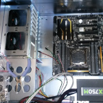
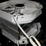
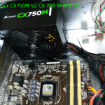
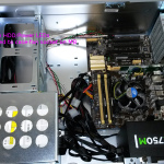
Big fans fit on both the top and bottom side of the cooler. There is enough room under the heatsink and fan for normal-sized RAM-sticks.
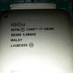
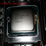
Intel Core i7-5820K 3,3 GHz LGA2011-3 CPU. For single-threaded benchmarks this is slightly slower than the i7-4770K I used in last weeks build, but it is 6-core instead of 4-core.
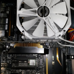
Note tight space between the GPU and the CPU-cooler. I added some kapton-tape on the GPU-card to avoid short-circuits. Asus GTX750TI-PH-2GD5 GTX 750 Ti 2048 MB GPU.
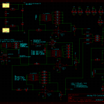
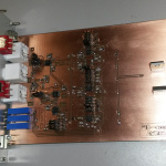
Here's an old-school PID controller based on simple op-amp circuits that I put together a week or so ago.
Schematic. Note that the DG418 switches are connected wrong – they were not used.
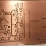
Milled PCB coated with PRF202 thru-solder clearcoat.
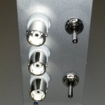
Schroff front-panel to fit 19″ 3U rack enclosure. Measure twice – drill once. The top switch resets the integrator, while the bottom switch enables the output.
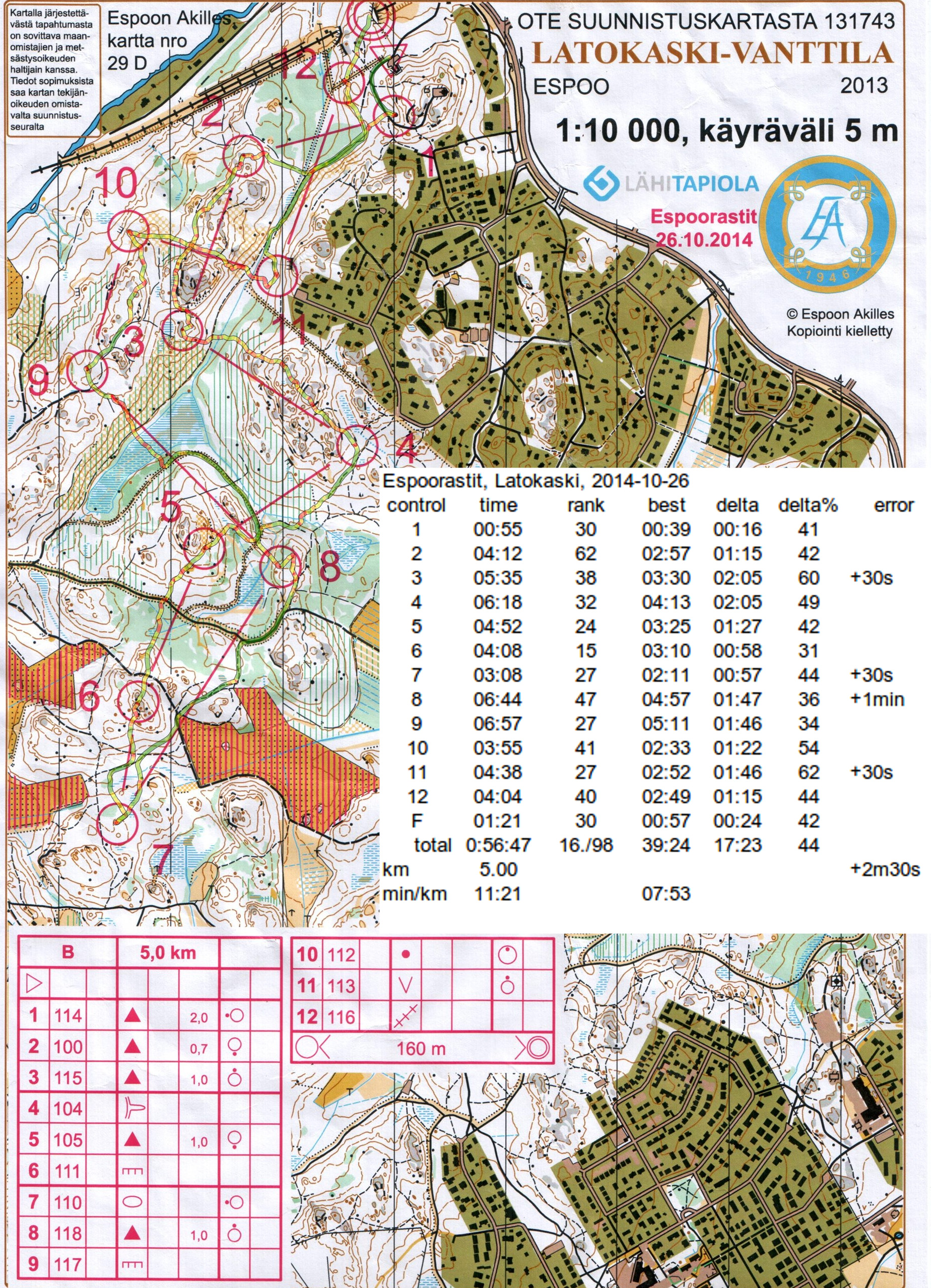
Pretty steady going with no major mistakes. Control #6 is the best split, the others look pretty bland, but the overall result is good since I am 16th out of about 100. The long straight path south of the #2-#3 line would maybe have been faster and easier. I almost ran past #8 before turning back. Close to #11 it was hard to tell where I had crossed the path+river.