Spindle servo Hall-signals


Figured out the hall- and resolver-signals on the spindle servo today. There are two scope-pictures but the hall signal corresponding to the third phase is also OK, I just didn't save the screenshot. The pinout seems to be:
1: resolver a+
2: resolver a-
3: resolver b+
4: resolver b-
5: resolver c+
6: resolver c-
7: Hall A
8: Hall B
9: Hall C
10: +5V
11: GND
12: PE/case-ground
The Hall outputs require pull-up resistors, this test was with 1 kOhm resistors. If I install a normal A/B/Z encoder on the motor myself I should be able to drive it with a stock standard Brushless servodrive.
Lathe CAD Screenshots


These Solidworks screenshots appear elsewhere on the interwebs too, but let's store them here also for reference.
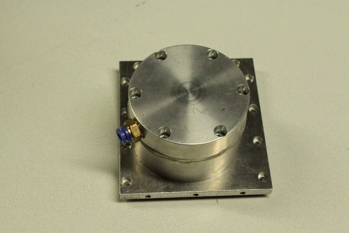
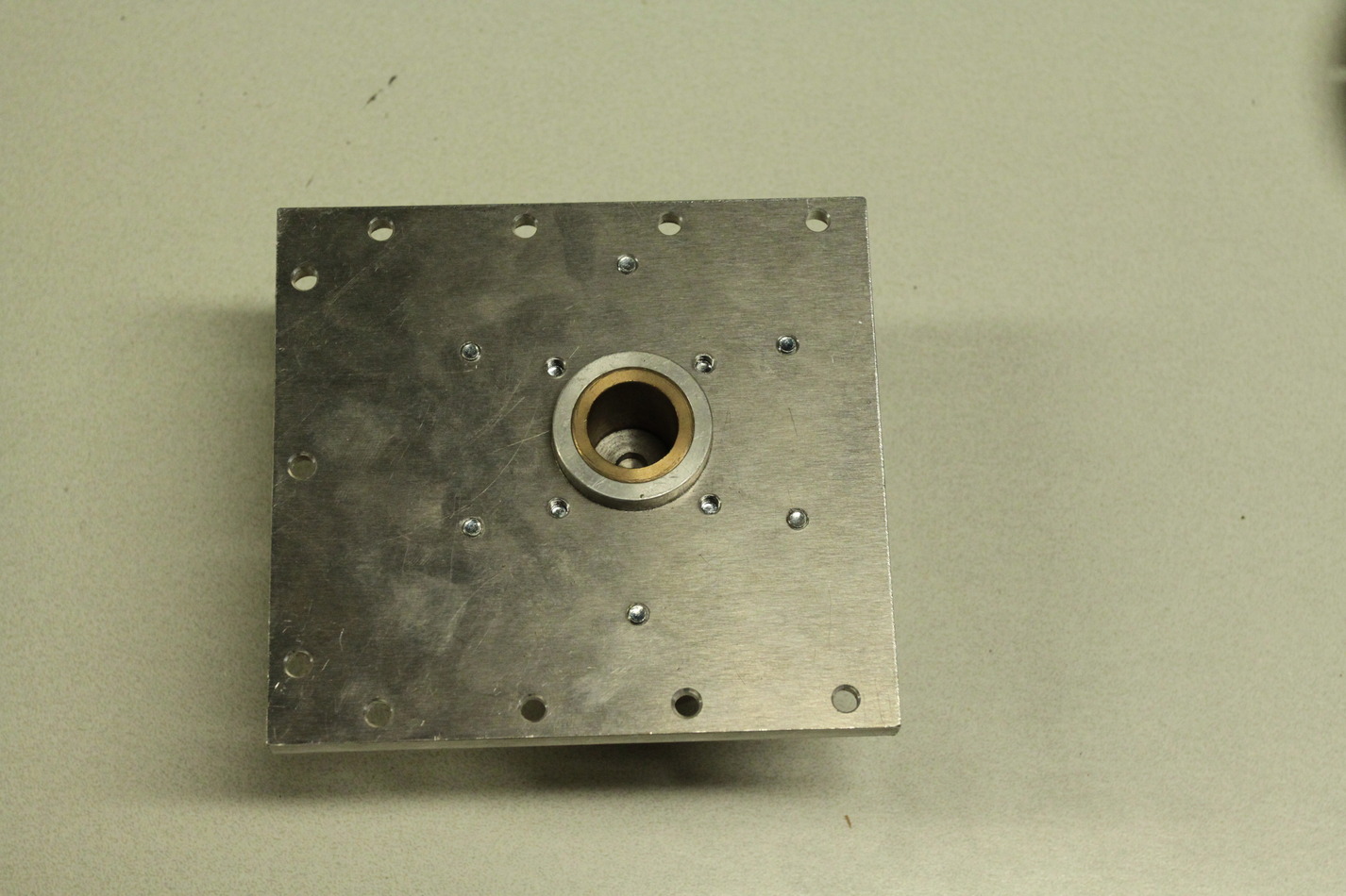
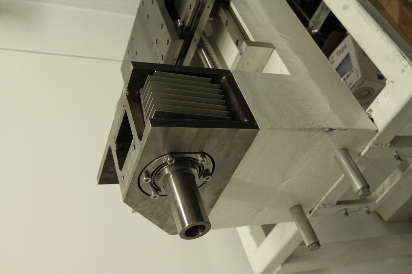
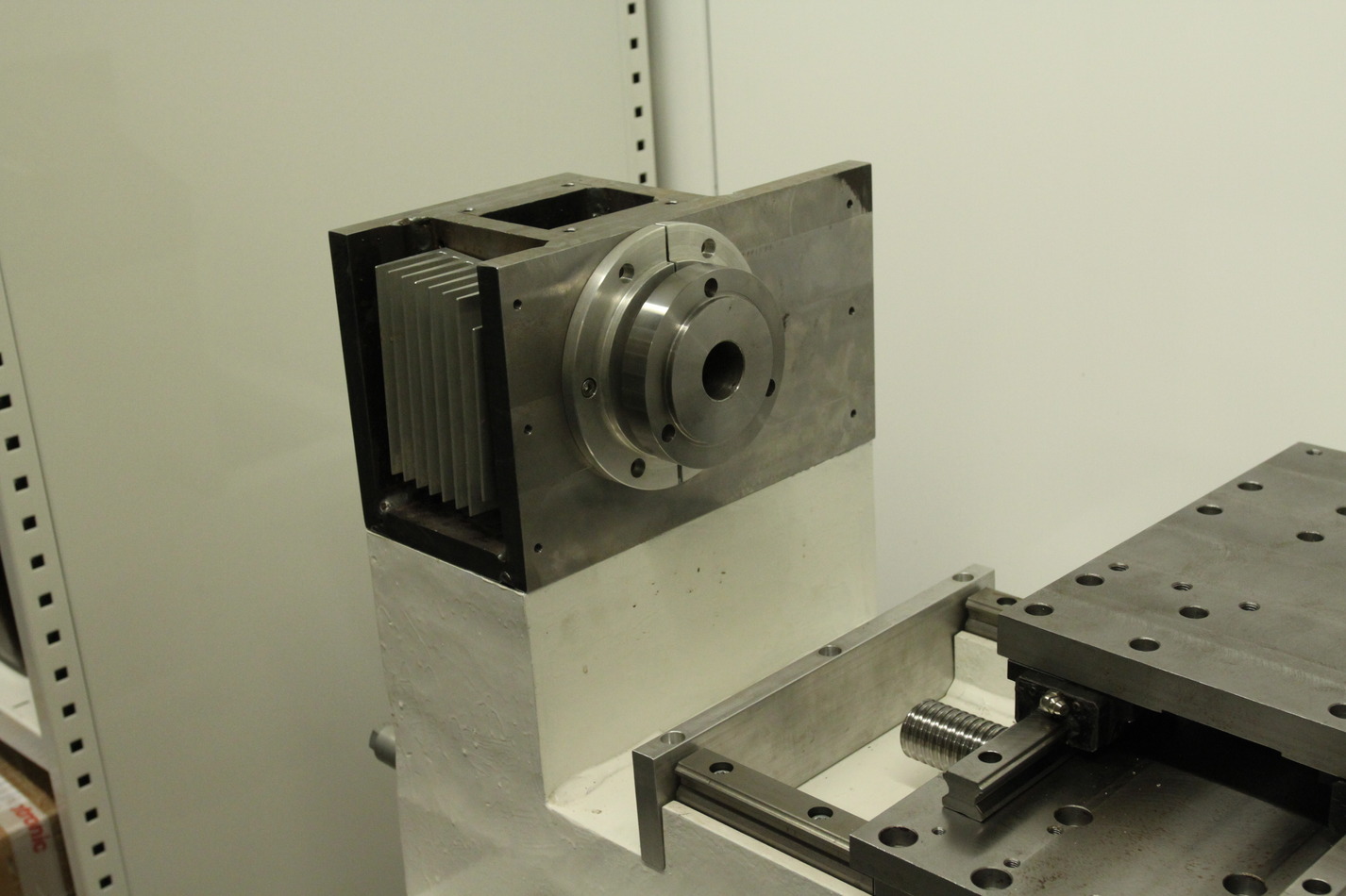
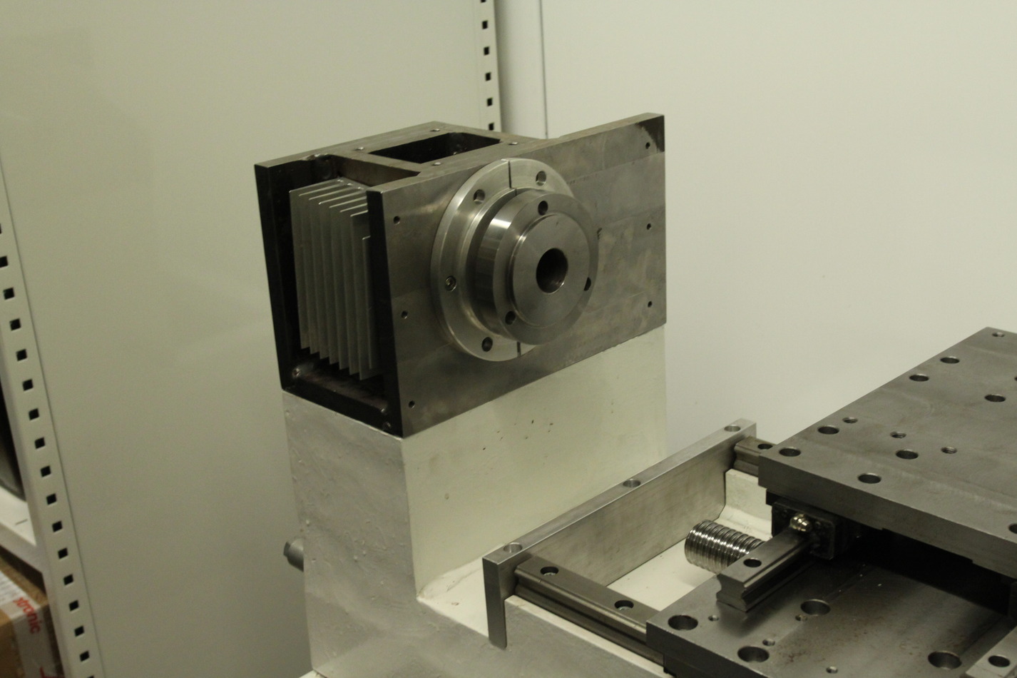
Lathe Spindle and Z-rail measurements
(the dial indicator reads in metric, with 1um resolution)
radially the spindle chuck-flange shows ca 14-15 um of runout.
Axially there is more wobble, ca 20um.
The Z-rails are very accurately aligned in the X-direction, I measured ca 6um error.
Measuring in the Y-direction, there seems to be a 40-50um jump around 10cm from the chuck. I'm not sure if that is important, since the rail-blocks don't make contact with the rail top surface. I think I need a way of measuring this again with the machine assembled.
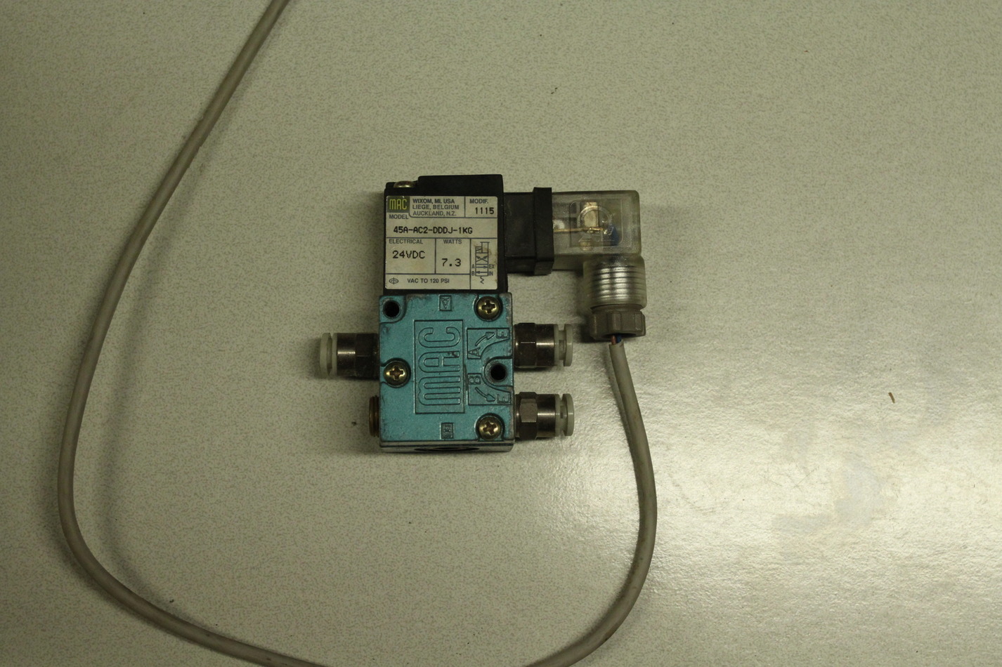
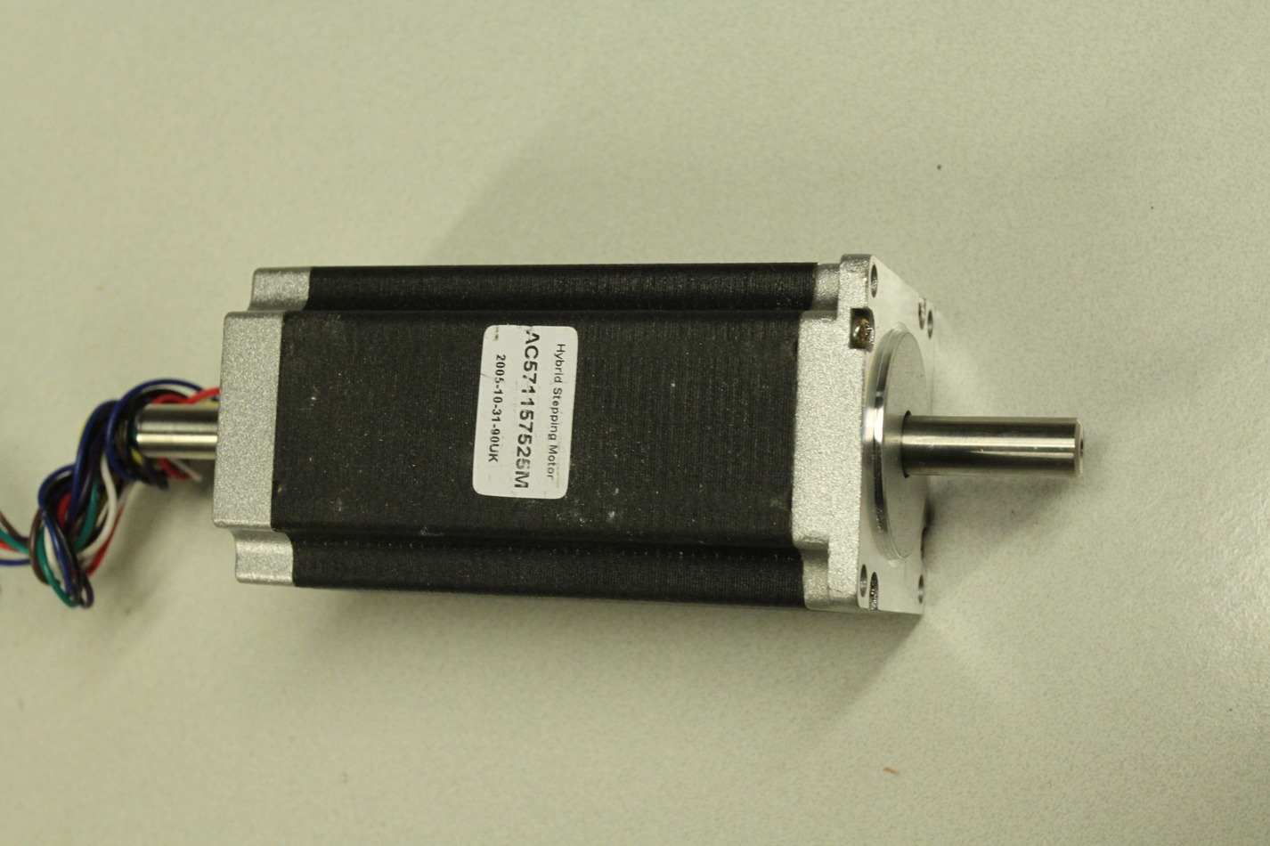
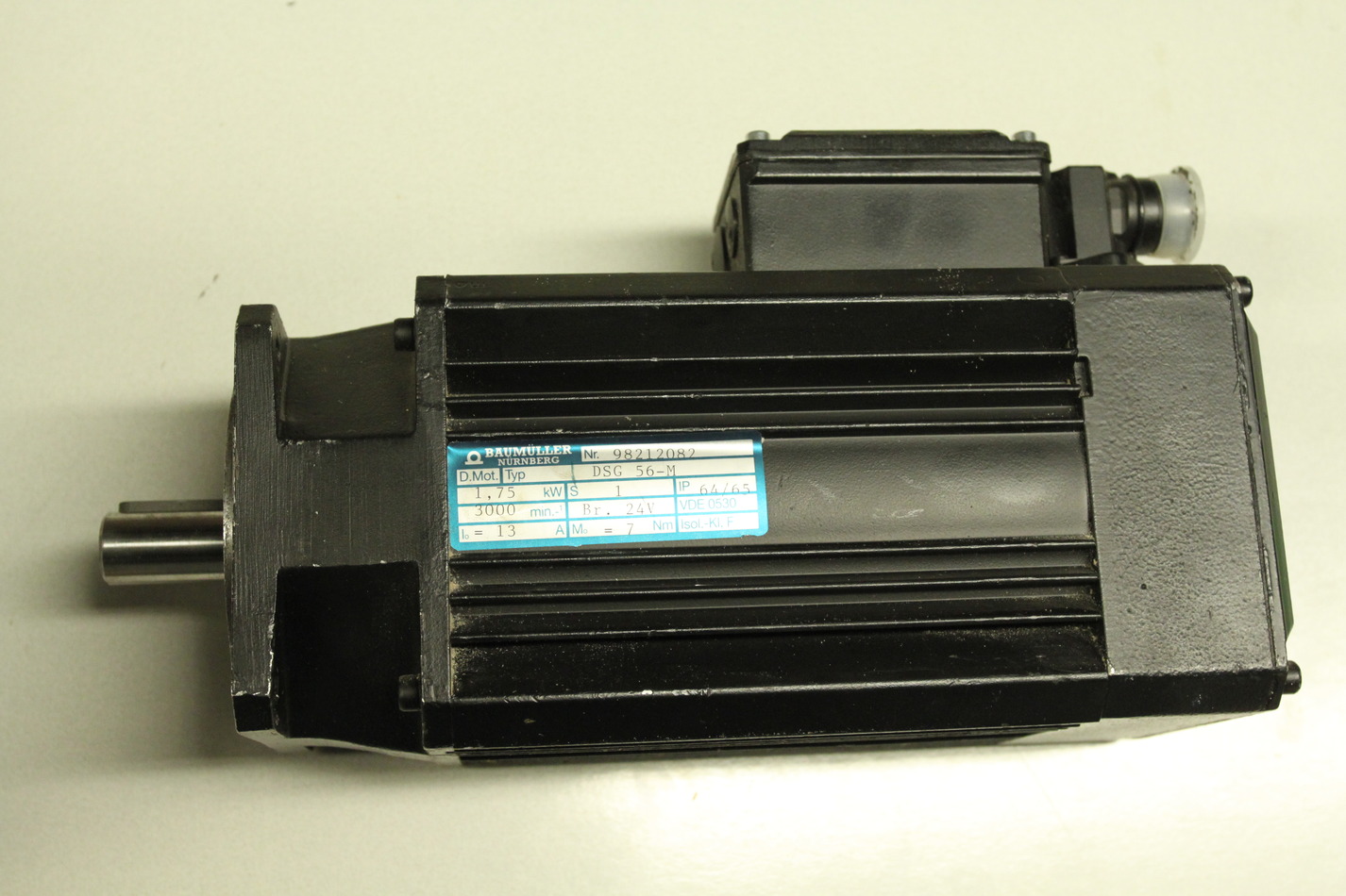
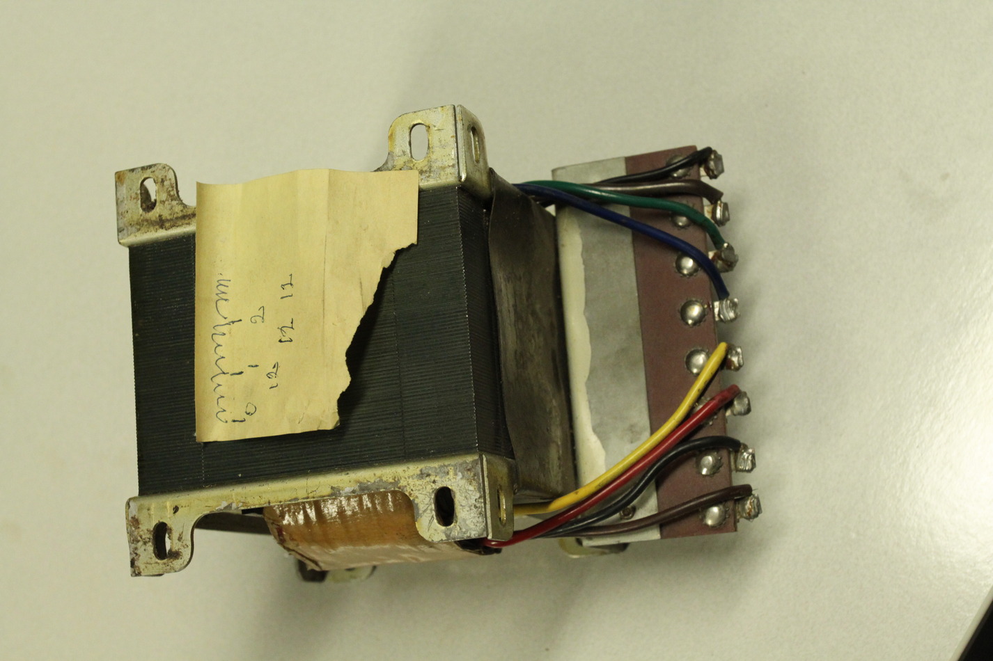
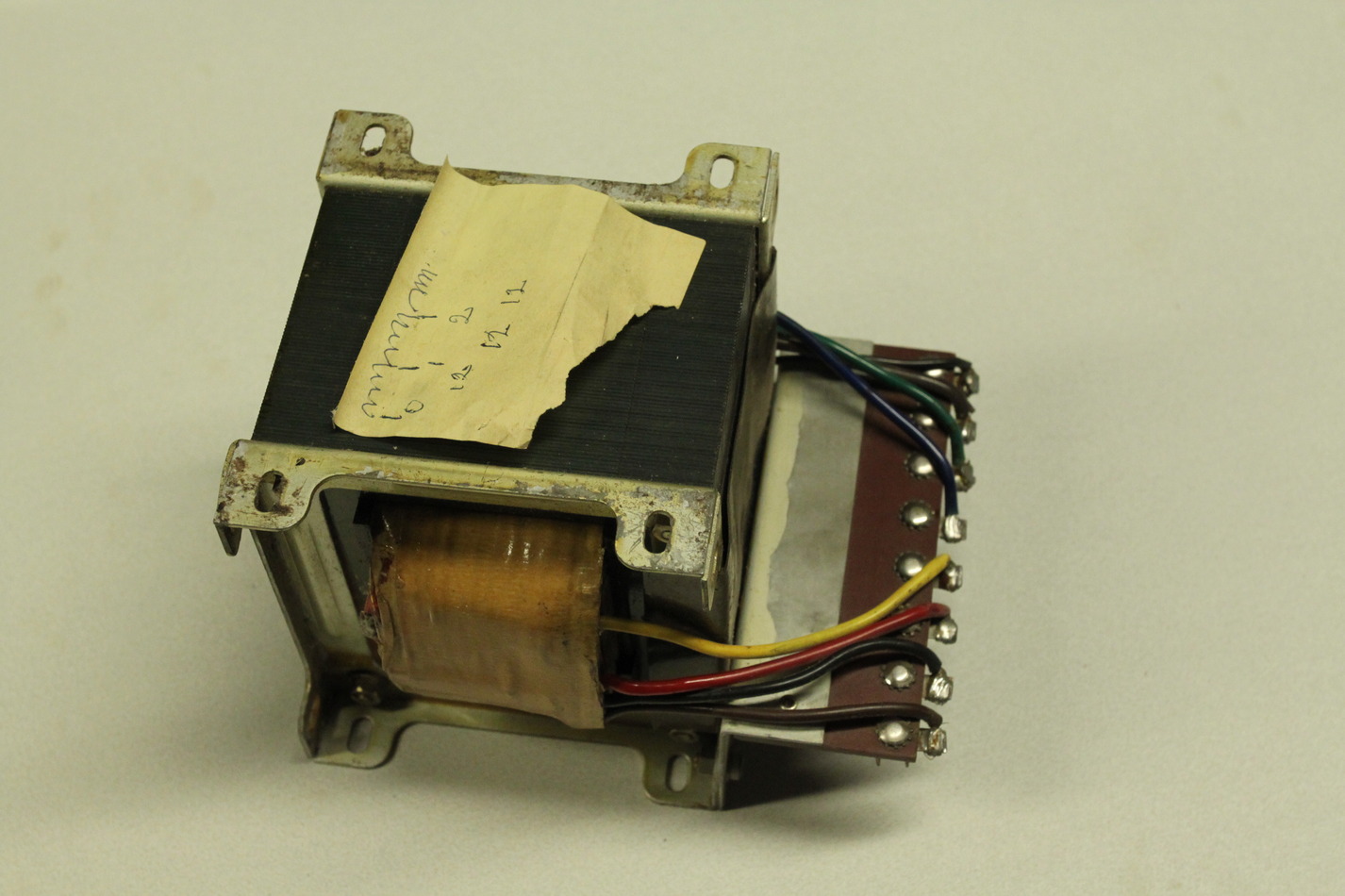
Lathe spindle servo


A closer look at the spindle-servo today. Googling for the model number does not immediately yield a datasheet, although I found a few similar-ish model numbers. The high-power connector is simple with U, V, W phases, Protective Earth, and +/- terminals for the solenoid brake. The brake opens at 24V and 0.67 A. The back can also be opened but doesn't reveal much more than an October 2001 manufacturing date. Hooking the scope to U, V, W and rotating the shaft with an electric drill produces some nice sine-waves. I'm not at all sure about the pinout of the encoder-connector, but looking at pairs 1/2, 3/4, and 5/6 seems to give something that could maybe be a resolver?
JHQ Lathe
I've bought a cnc-lathe!
Well, it's not complete, more of a cnc-lathe project.
A fellow Finnish cnc'er "JHQ" started this project a few years ago, but as he now has a 5000 kg professional cnc-lathe and his own company, he hasn't had time/money to complete this project. There are many project logs out there with details of how the machine was designed and built:
http://cnczone.com/forums/showthread.php?t=27031
http://www.cnc-tekniikka.com/CNC-forum1/index.php?topic=121.0
http://www.robosota.fi/foorumi/viewtopic.php?t=935
http://www.devonparkour.com/ukcnc/forum/viewtopic.php?f=6&t=9
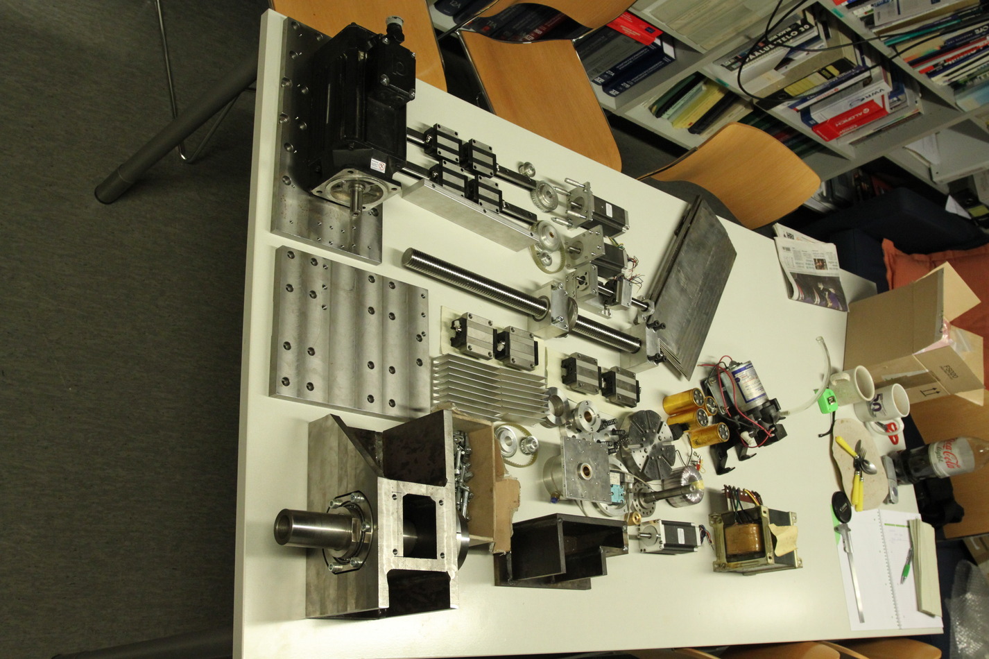
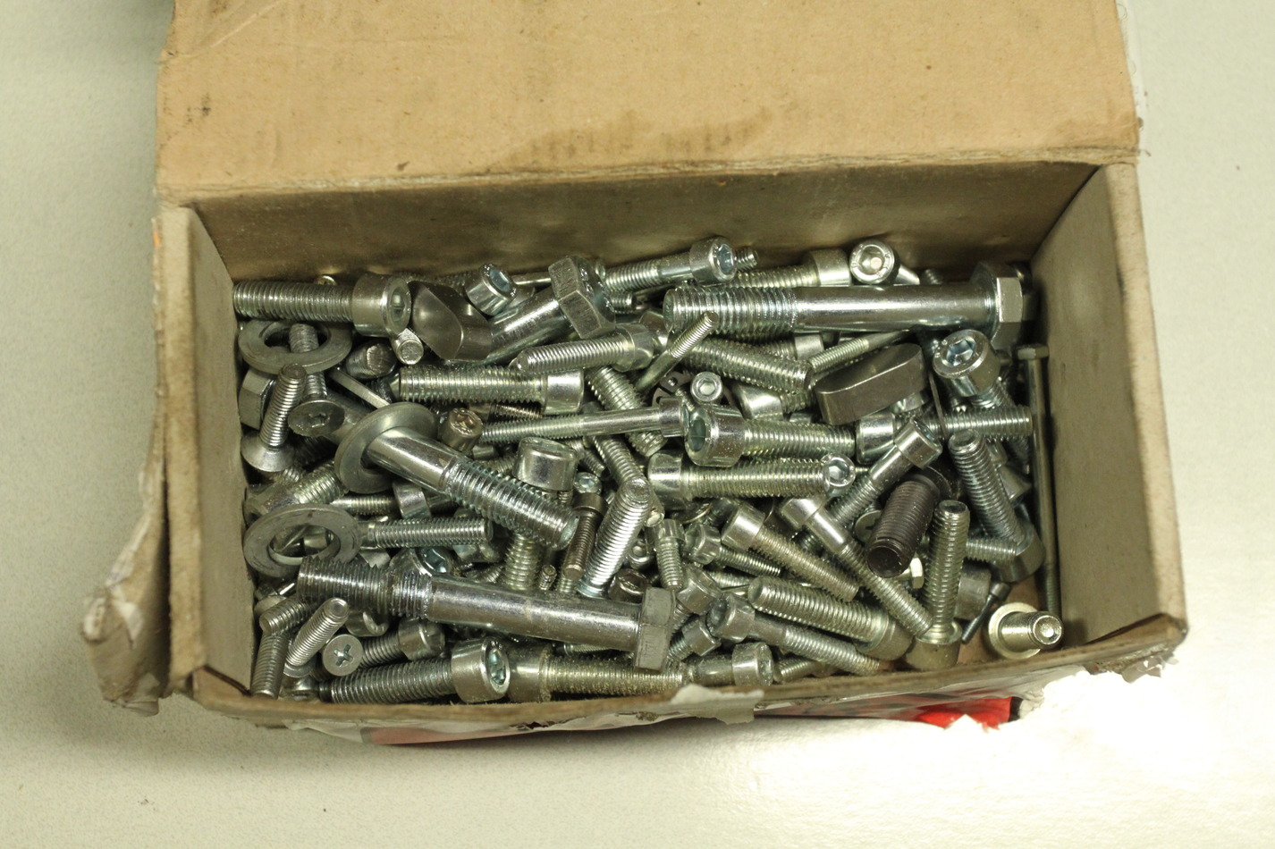
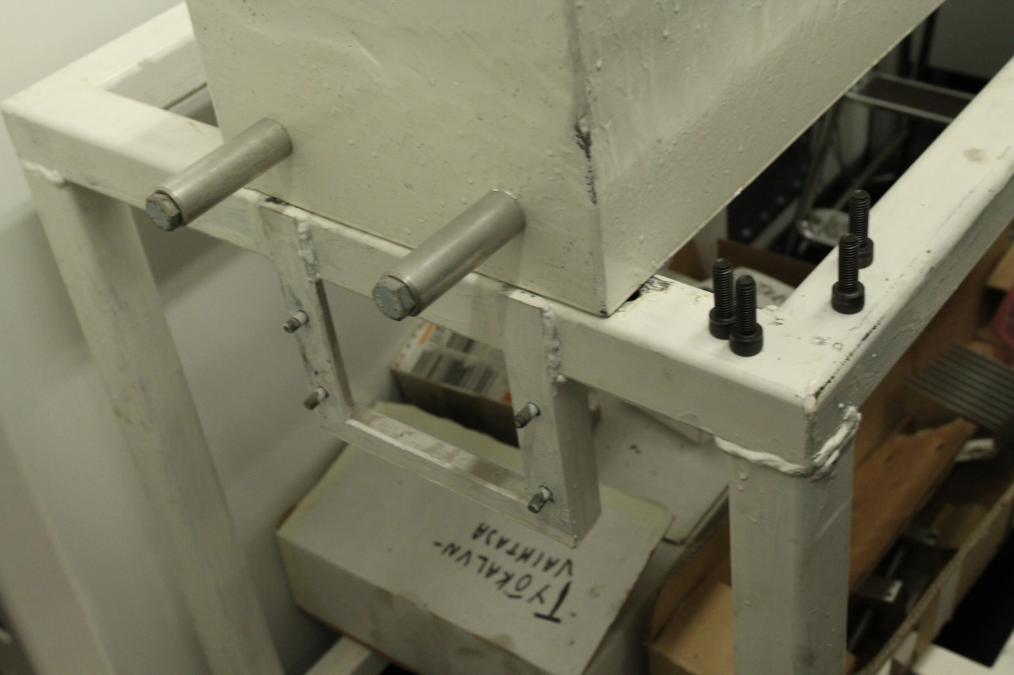
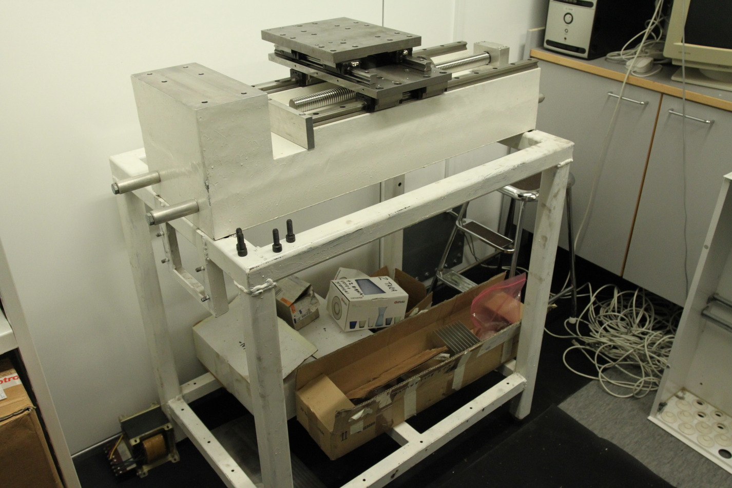
Some notes of my own, as I unpacked everything today.
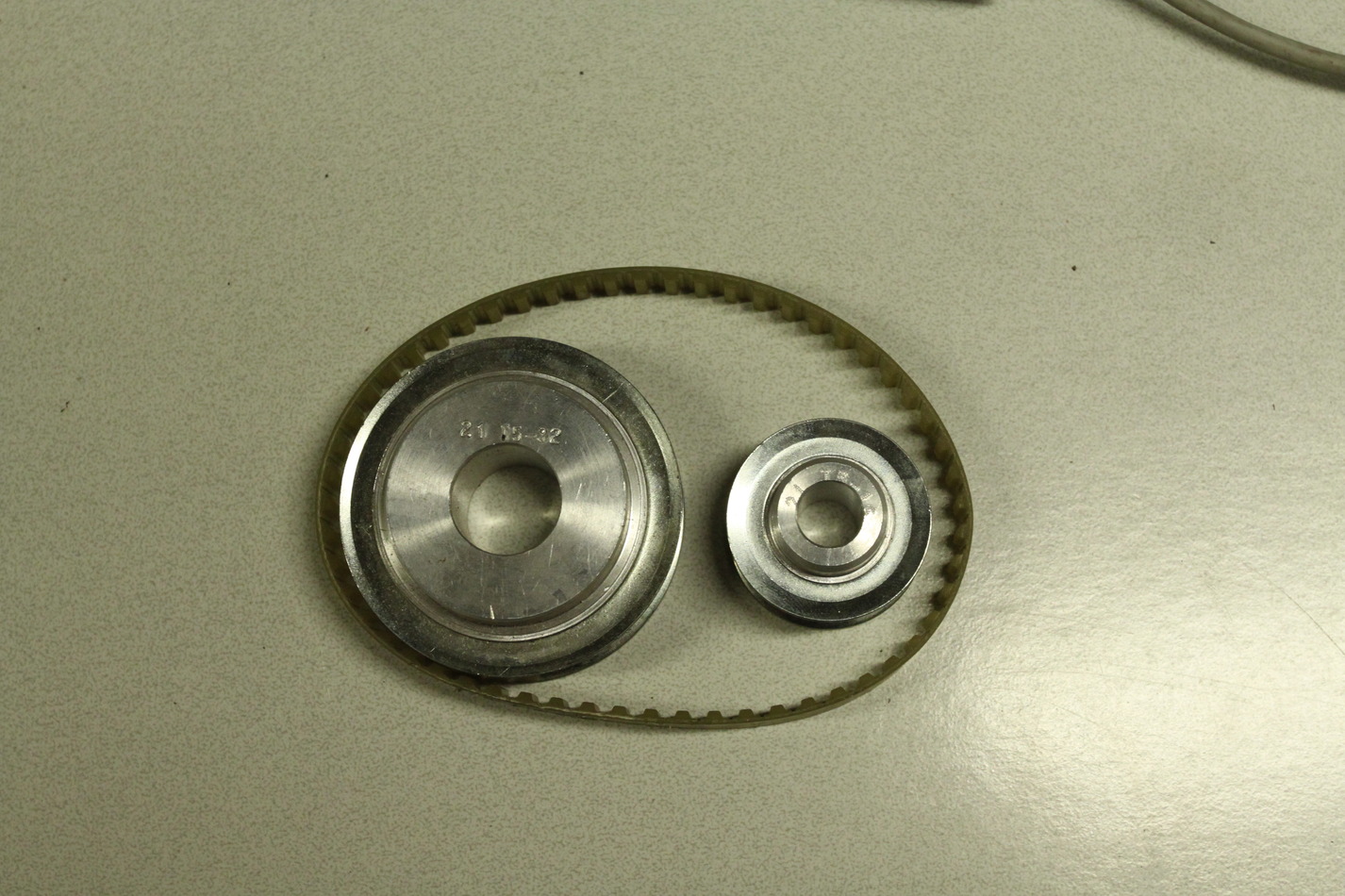
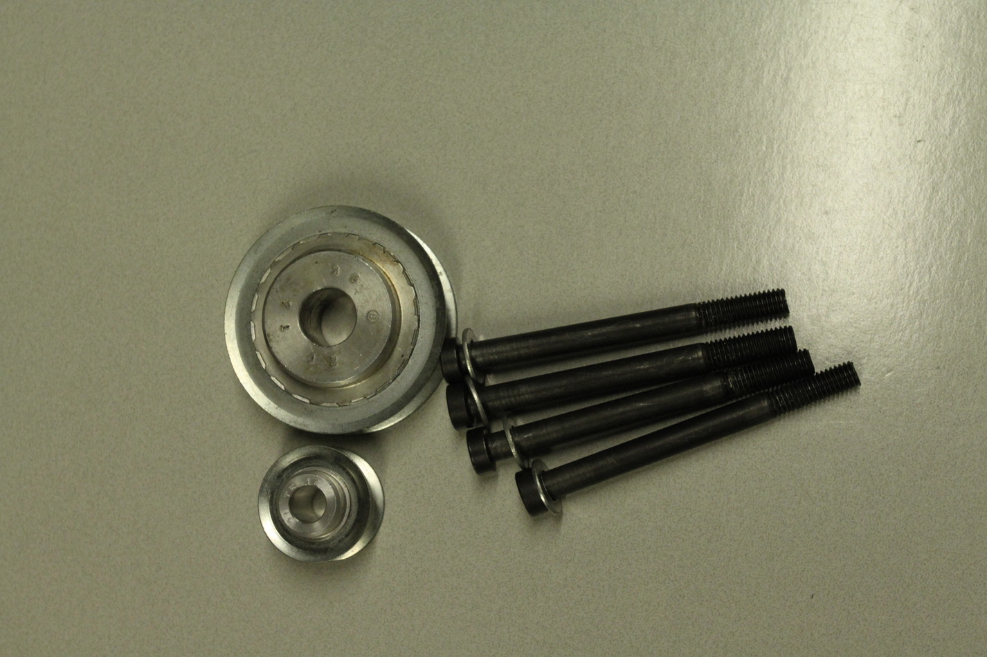
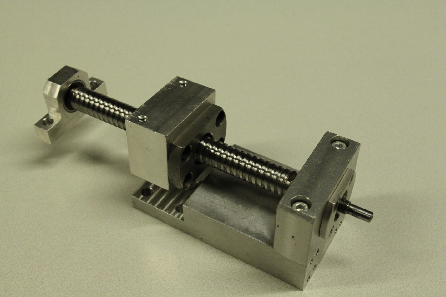
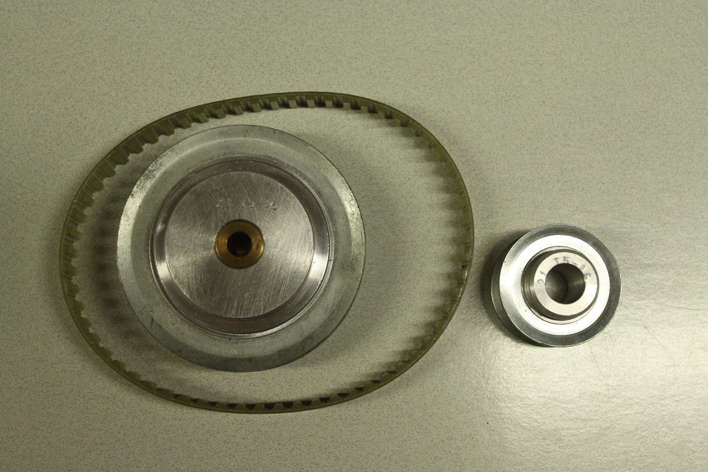
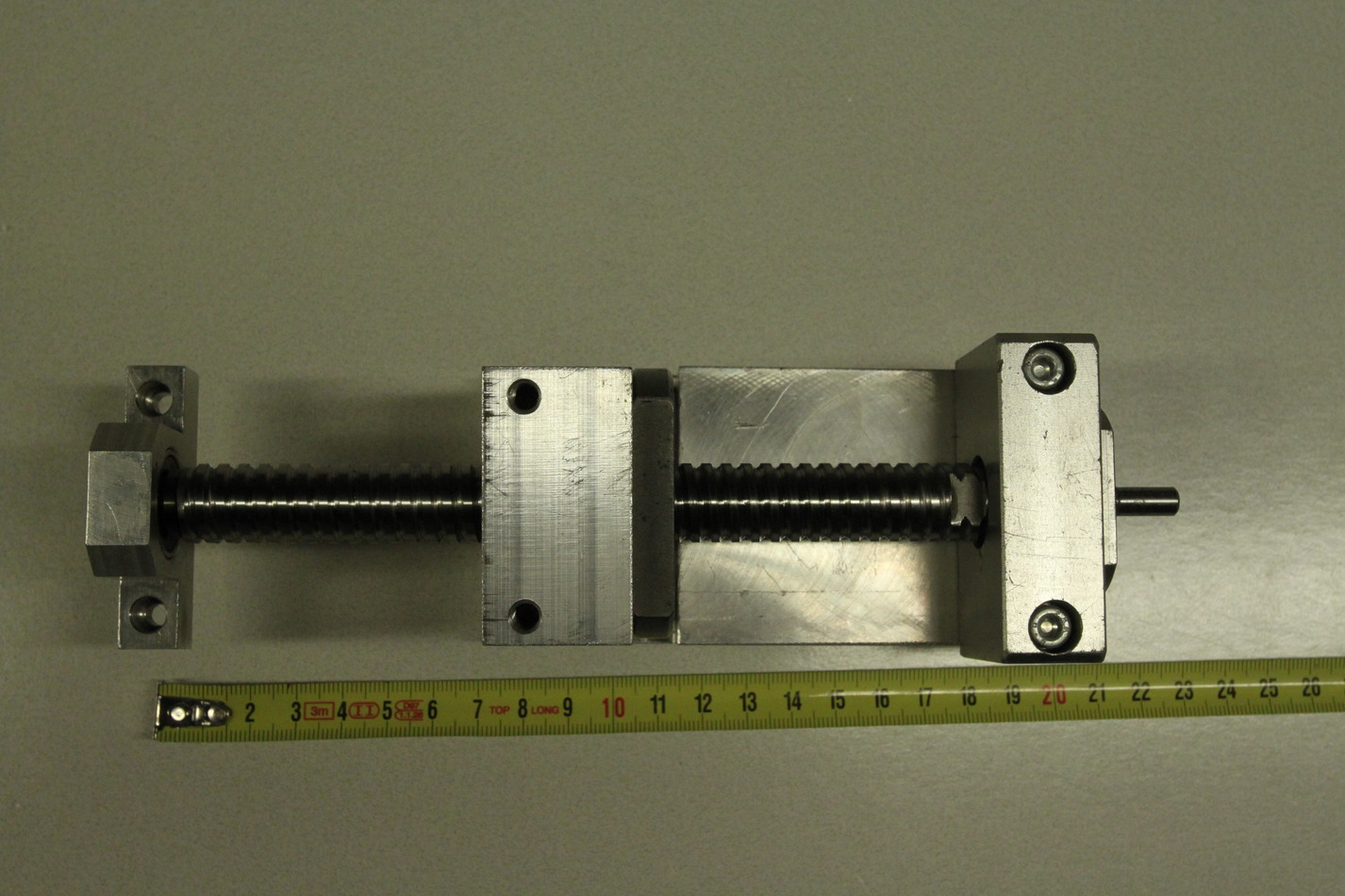
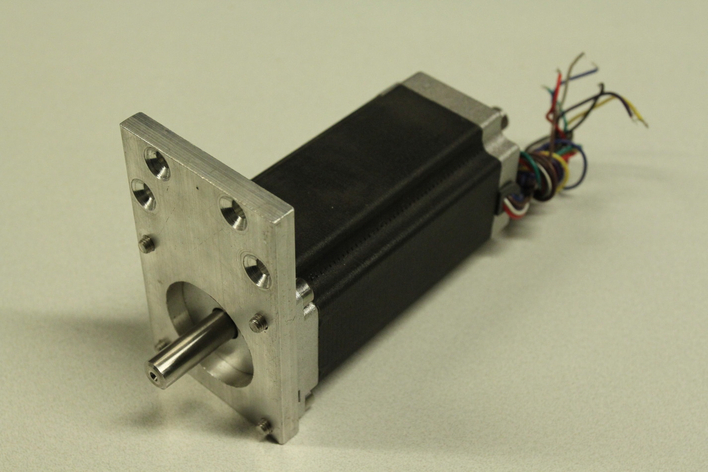
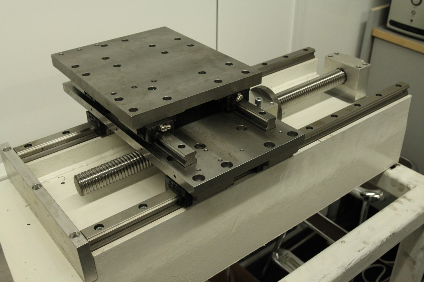
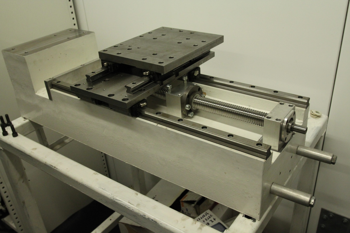
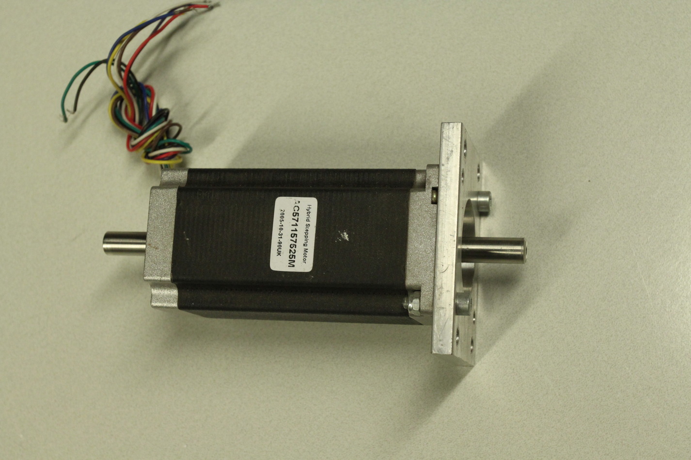
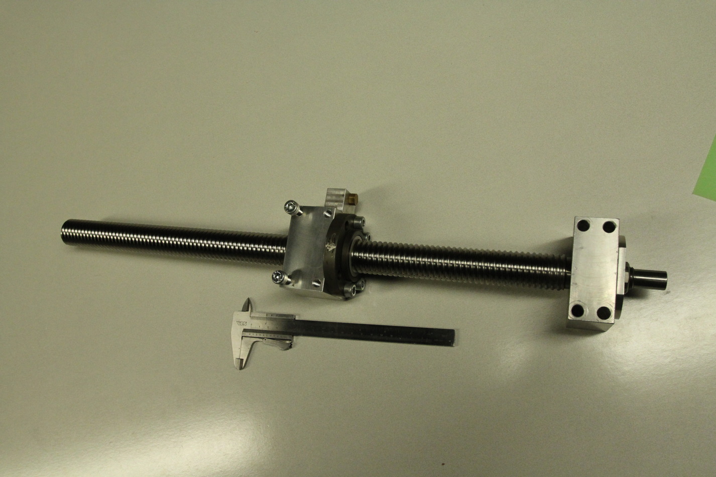
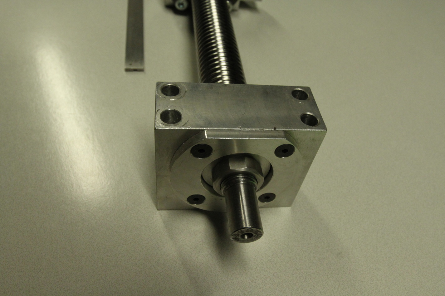
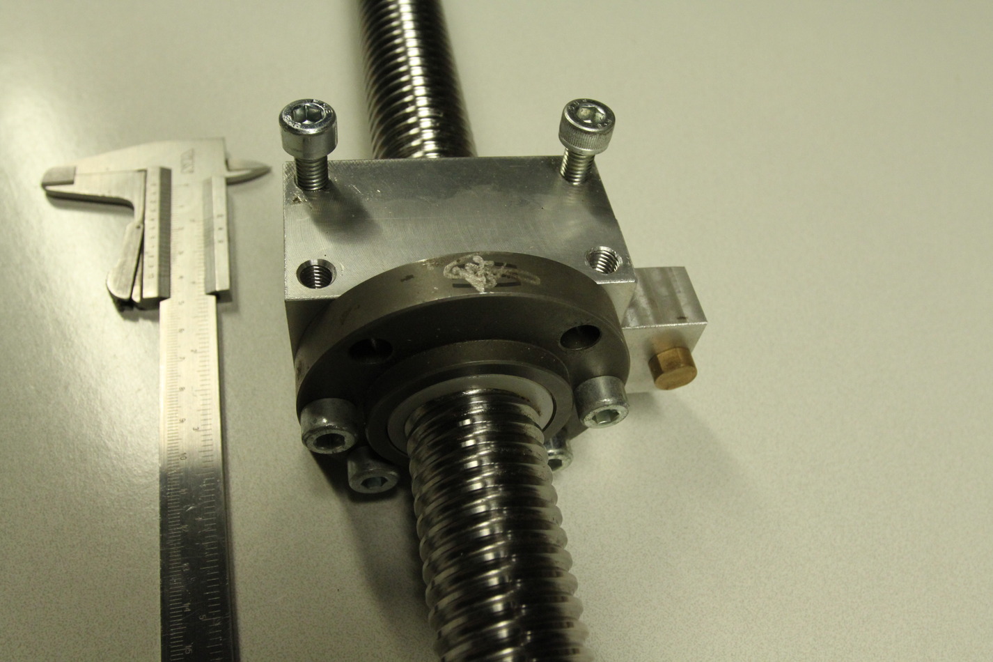
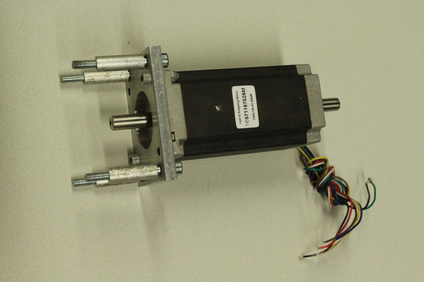
Stepper motors are NEMA23 size with 10 mm diameter shafts (ca 20 mm long). I will most probably not use stepper-motors but NEMA23-size brushless servos instead. The X-ballscrew is 16mm diameter with 4mm lead. It is 158mm long while the nut is 37mm long. That makes for a theoretical max travel of 121mm (enough?). The timing belt pulleys for both Z- and X-axes are type 21T5-36 and 21T5-21 or 21T5-16. That makes for a 1:1.7 or 1:2.25 reduction ratio. The Z-ballscrew is ca 30mm diameter with a 5mm lead (might be 0.2" also). It is 545mm long, the nut is 63mm long, theoretical travel 482mm.
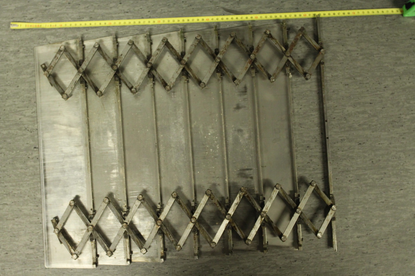
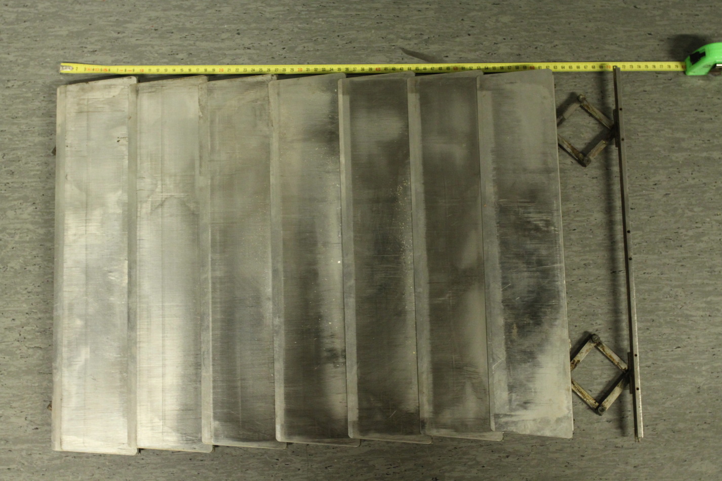
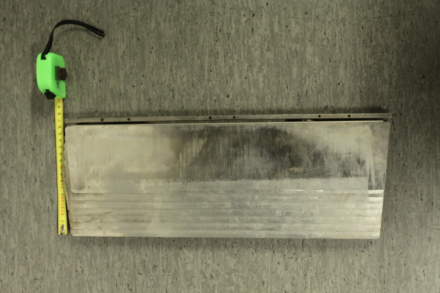
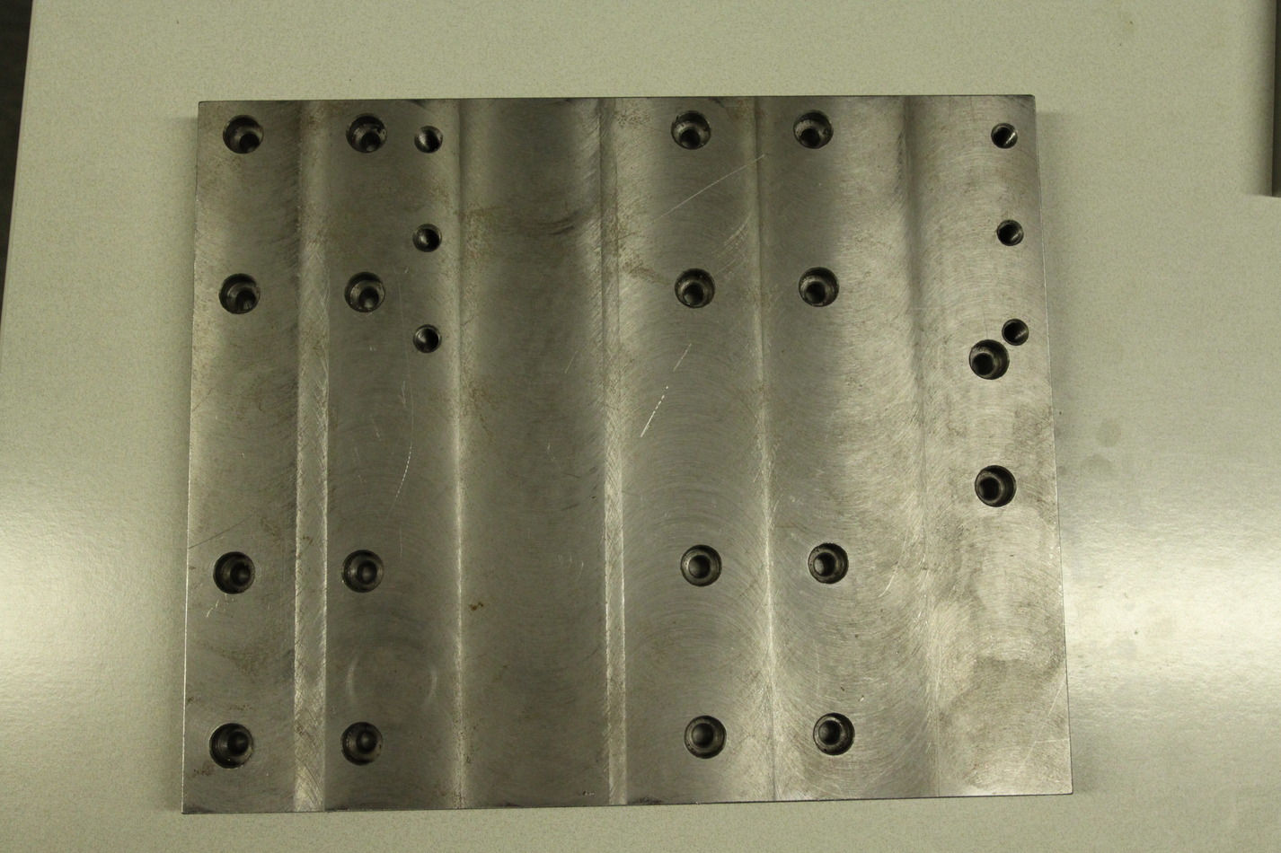
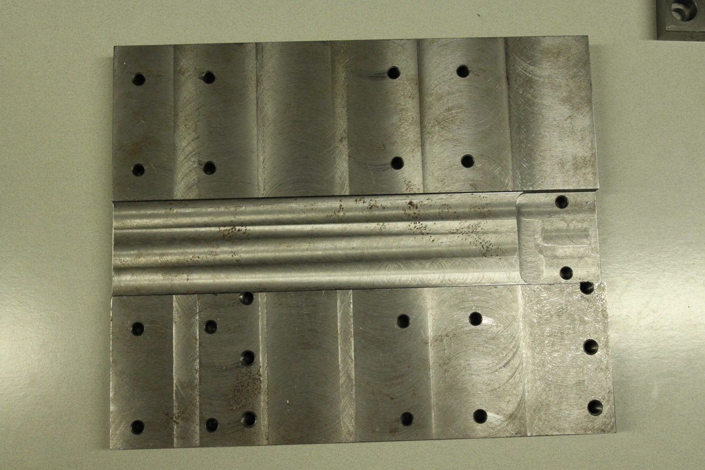
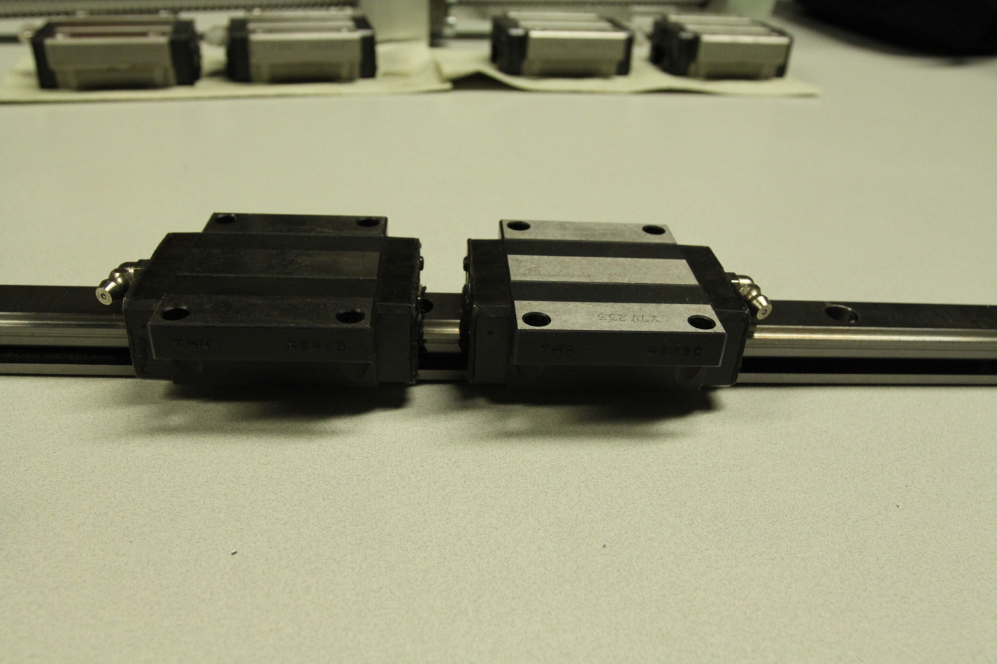
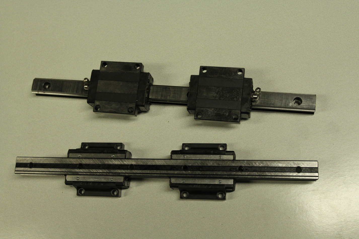
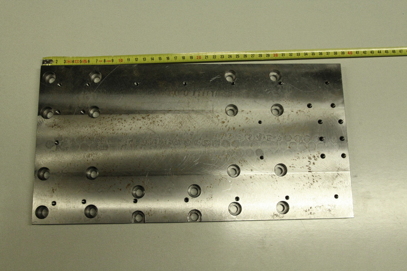
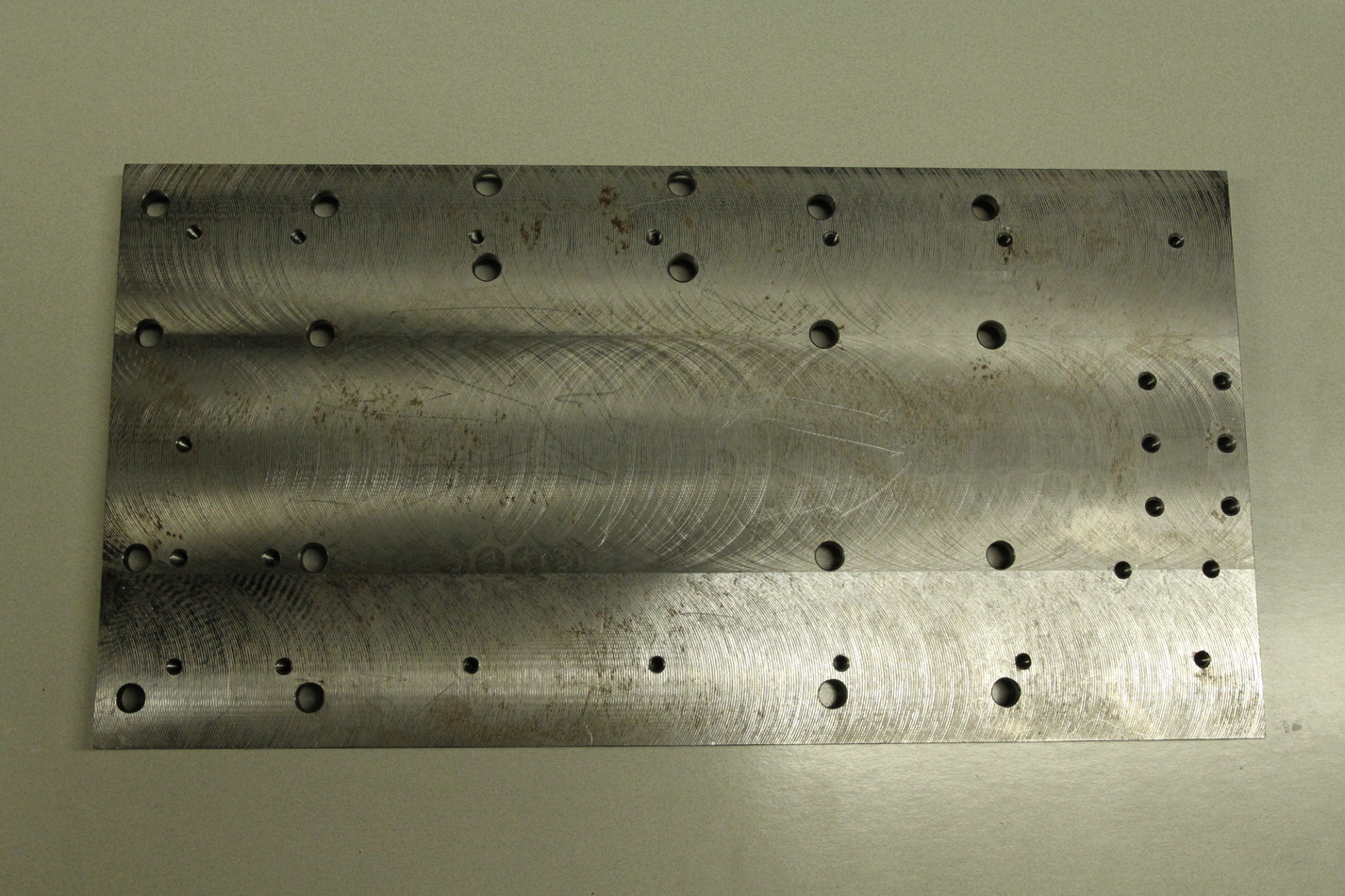
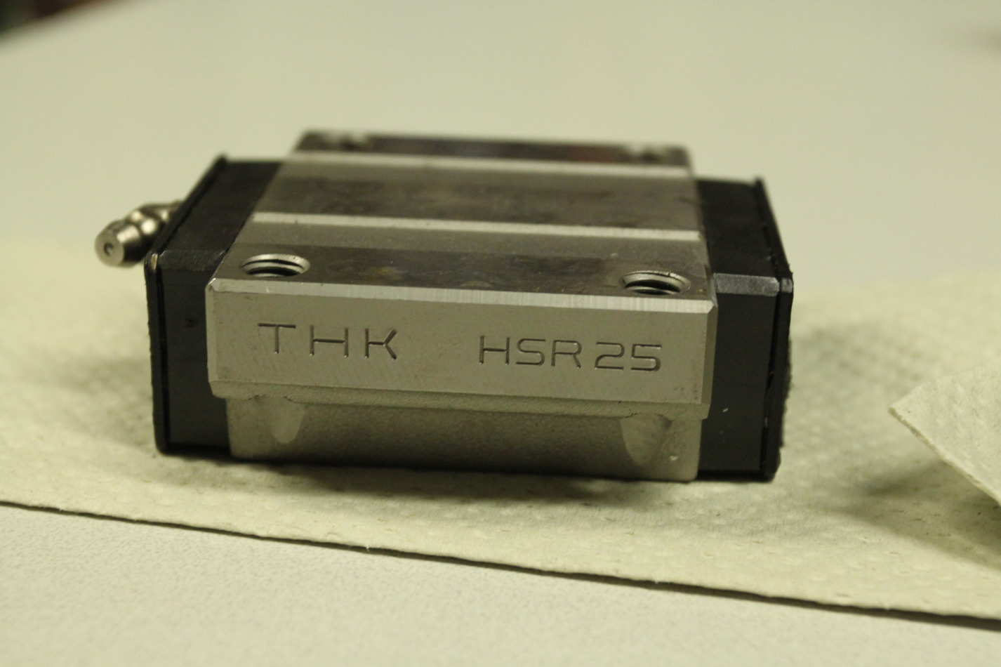
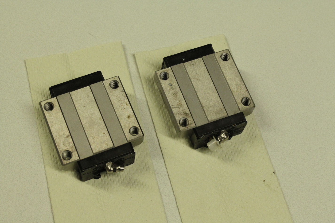
The chip-guard is ca 450-460mm wide and around 185mm long when fully compressed. It extends to much longer than required. The Z-rails are HSR25 type and the X-rails are HSR20 type (length 340mm). The Z-saddle-plate is 380x195x15.3mm. The X-saddle-plate is 275x227x20.4mm.
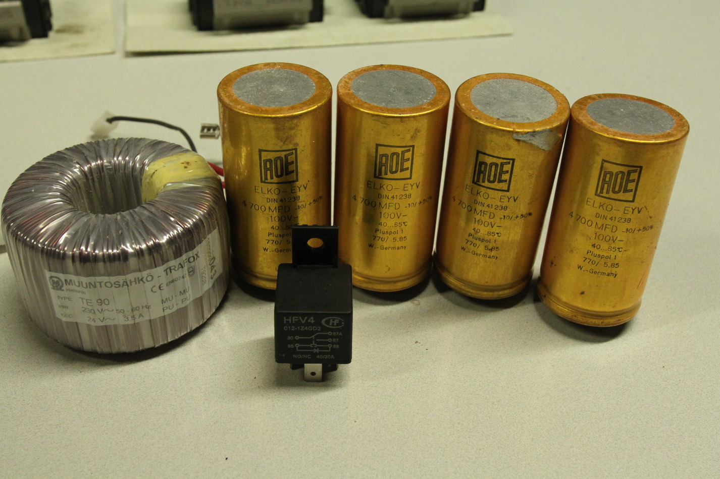
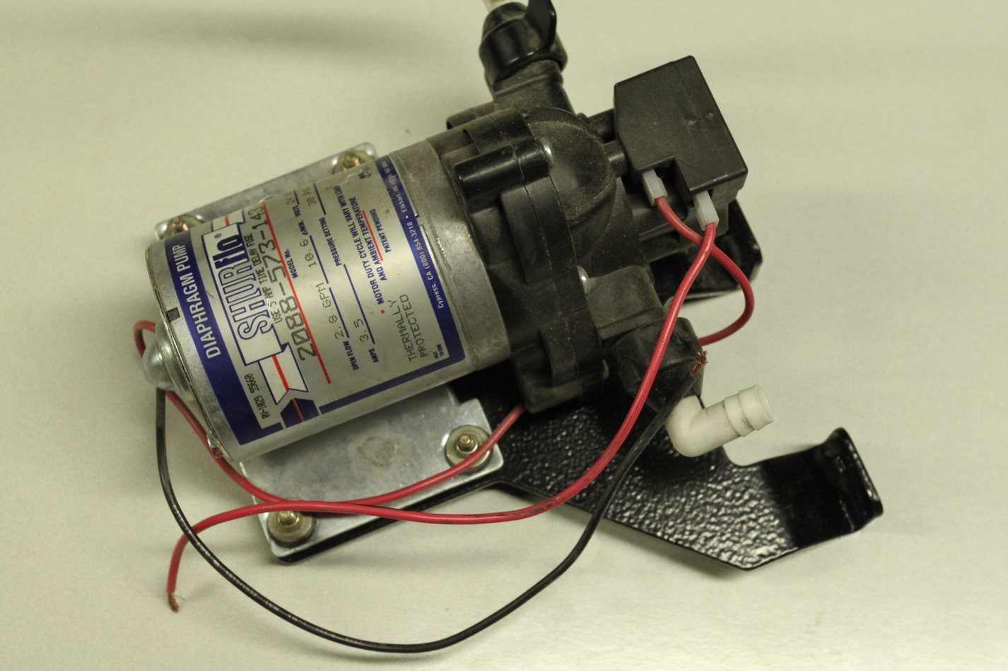
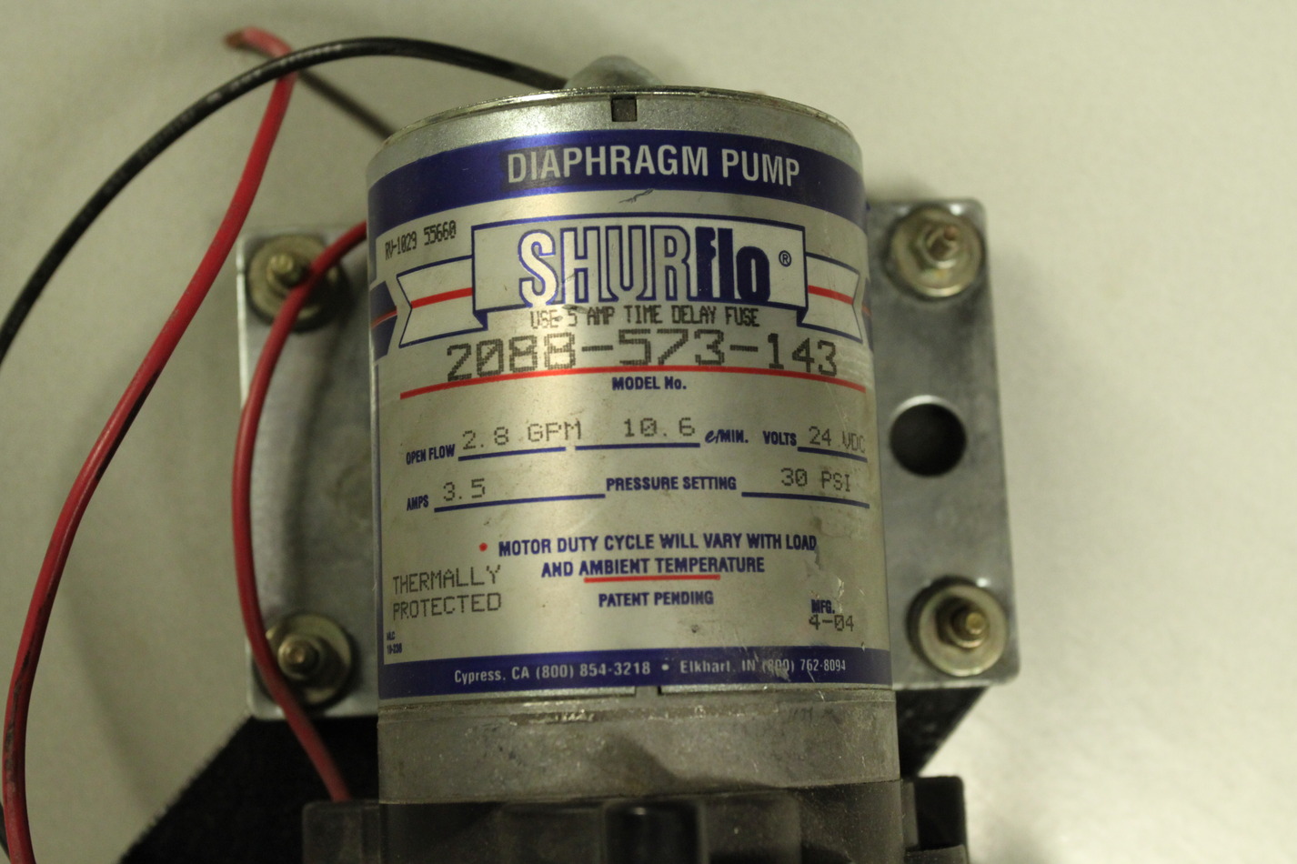
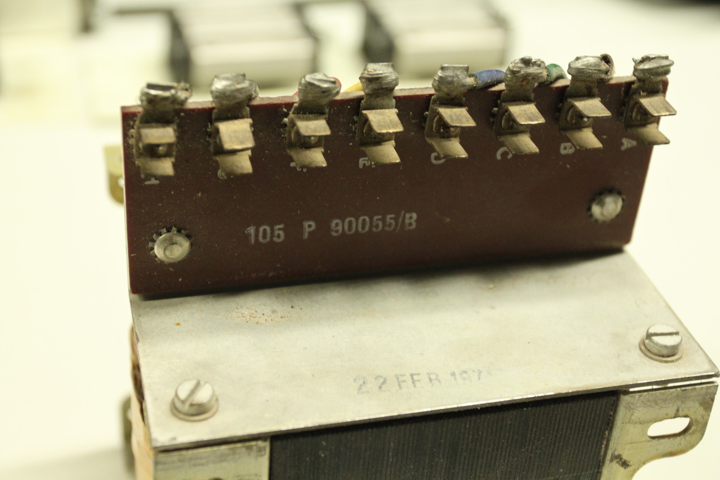
The coolant pump is rated as 24V/3.5A. There is a transformer with a 24V/3.5A secondary for powering the coolant pump.
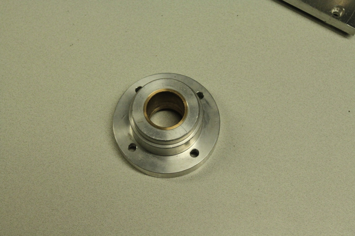
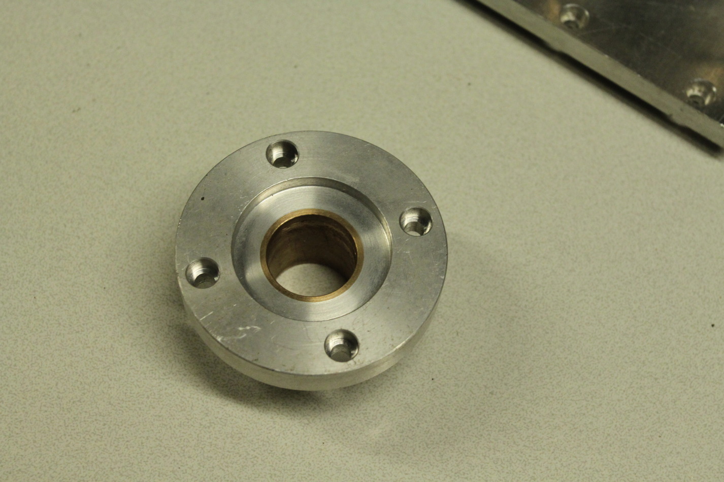
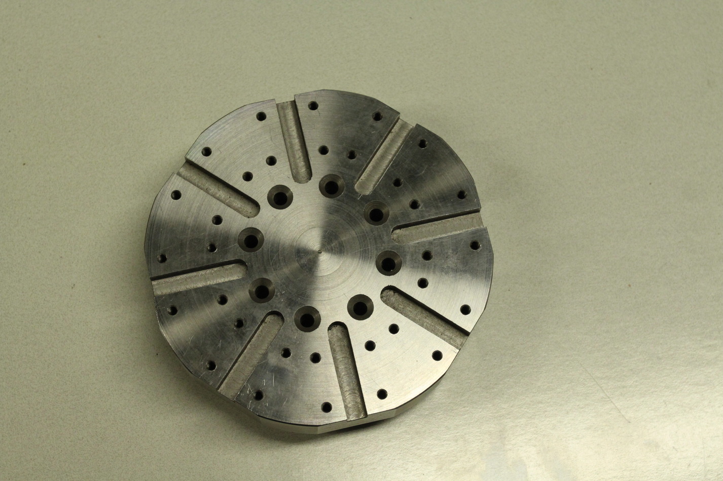
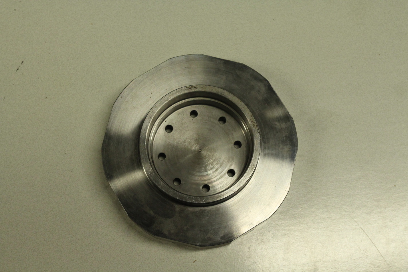
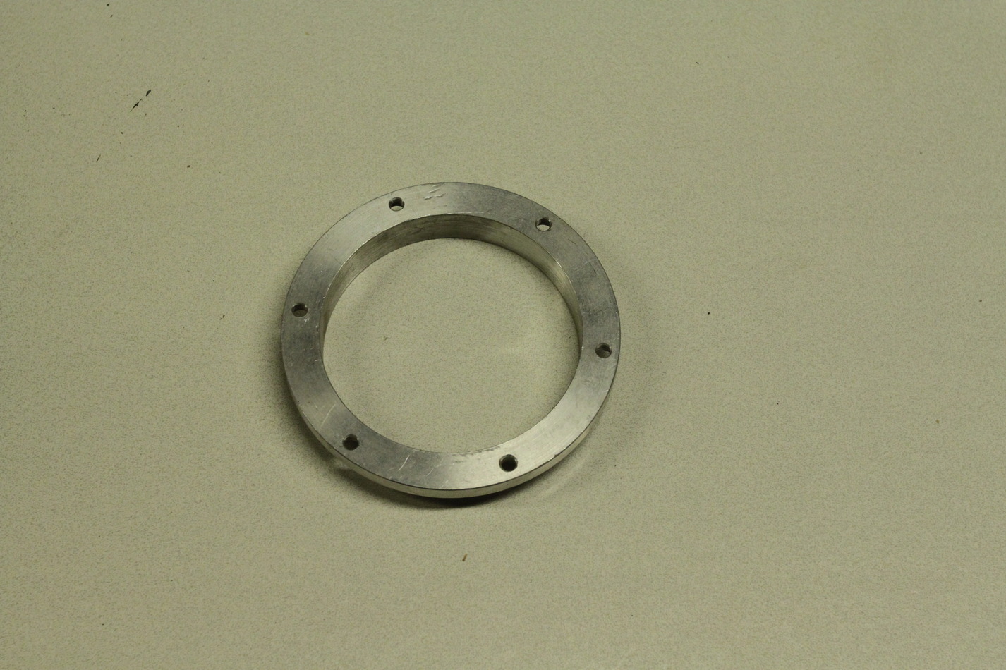
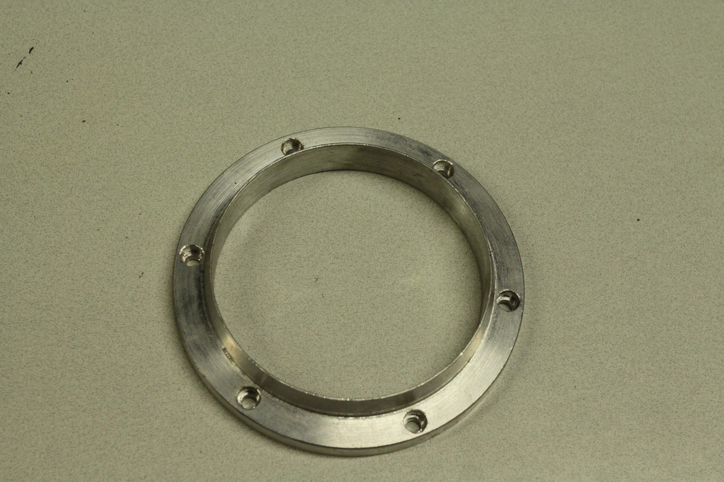
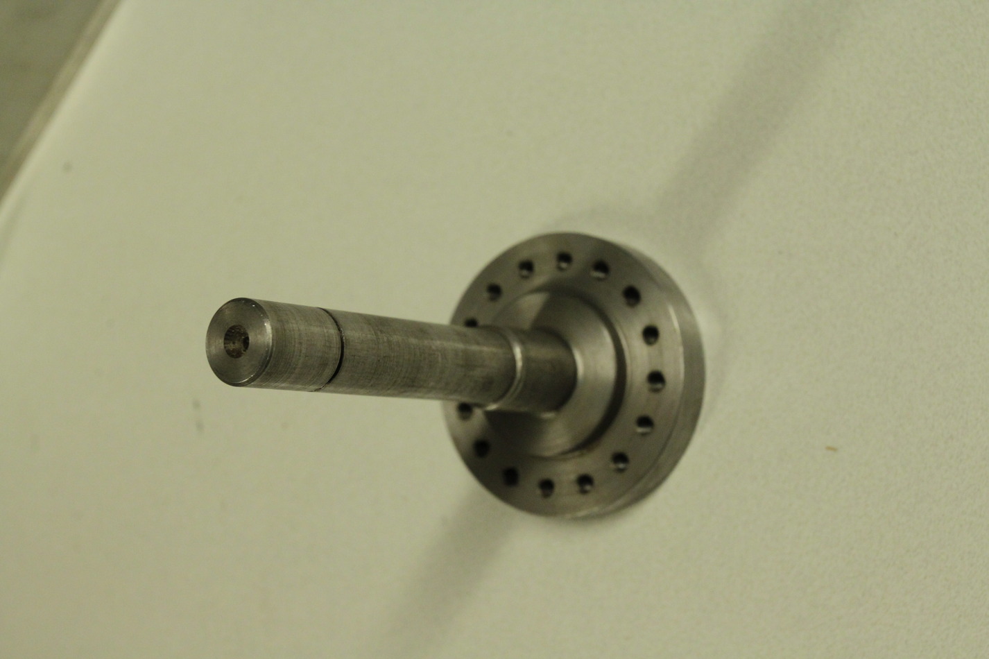
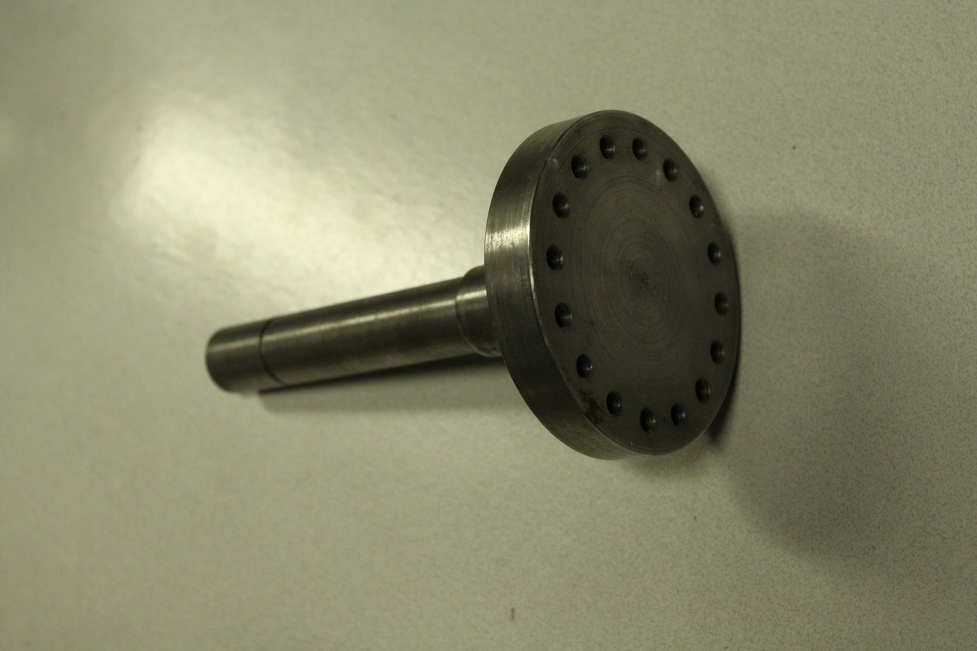
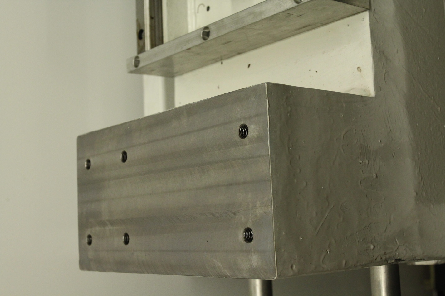
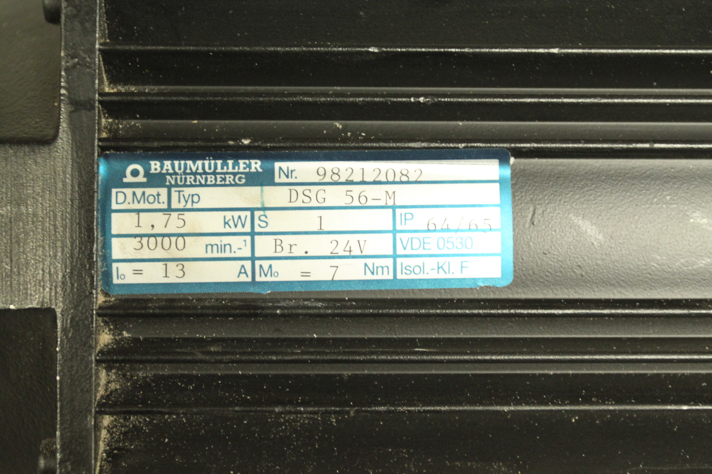
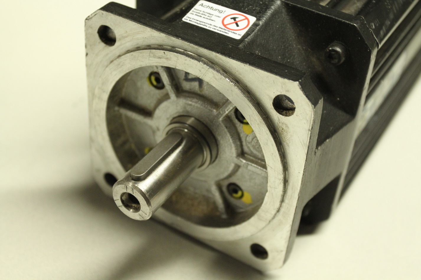
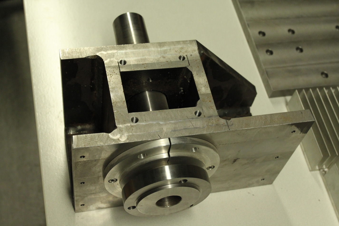
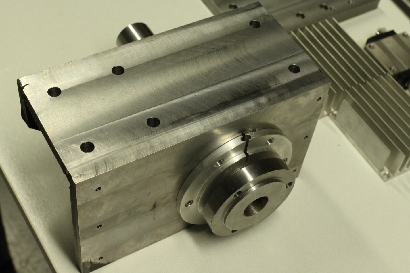
The spindle servo is rated at 1.75kW, 3000rpm, 13A, and 7Nm. The spindle servo axis is 19mm in diameter and ca 35mm long. The spindle itself is 45mm in outer diameter where the pulley for the belt-drive should attach. The chuck-holder is 100mm in diameter.
These images are also on picasa: http://picasaweb.google.fi/anders.e.e.wallin/JHQLathe2009_11_21#
Links - 2009 Nov 19
- Mandelbulb formula… -
- 11/16/09 PHD comic: 'Buzzwords' -
- Leaked: Lenovo ThinkPad T410s coming January, minor upgrades -
- Clouds and more clouds - Even J-P who has multiple APODs is getting a bit frustrated!
- Trapping double negative particles in the ray optics regime using optical tweezers with focused beams -
- Highly birefringent vaterite microspheres: production, characterization and applications for optical micromanipulation -
- Design of a NURBS interpolator with minimal feed fluctuation and continuous feed modulation capability -
- Astrophotography with a Canon Telephoto -
- Plastic Boat: The Building of a High-Tech Eco-Stunt - Plastiki
- "Mandelbulb," a 3D Mandlebrot Construct, Discovered - OMG. check these pics!
- Design of a NURBS interpolator with minimal feed fluctuation and continuous feed modulation capability -
- LACERTA M-GEN Stand-Alone Autoguider -
- More Next-Level Musicmaking on YouTube: The ‘Crowdsourced’ Single -
- Underwater Glider Hunts, Records Cryptic Whales -
- High resolution miniature dilatometer based on an atomic force microscope piezocantilever -
- Multiple traps created with an inclined dual-fiber system -
- This hobby can be really dangerous. -
Sunday 8k

Any snow and ice that was on the streets is gone again and +4C with little wind is quite ideal for running. 8.10km in 54 minutes makes for a leisurely 6:46min/km pace.
OpenMP test on i7
Here's a simple piece of c-code (try zipped version) for testing how to parallelize code with OpenMP. It compiles with
gcc -fopenmp -lm otest.c
The CPU-load while running looks like this:

Looks like two logical CPUs never get used (two low lines beyond "5" in the chart). It outputs some timing information:
running with 1 threads: runtime = 17.236827 s  clock=17.230000

running with 2 threads: runtime = 8.624231 s  clock=17.260000

running with 3 threads: runtime = 5.791805 s  clock=17.090000

running with 4 threads: runtime = 5.241023 s  clock=20.820000

running with 5 threads: runtime = 4.107738 s  clock=20.139999

running with 6 threads: runtime = 4.045839 s  clock=20.240000

running with 7 threads: runtime = 4.056122 s  clock=20.280001

running with 8 threads: runtime = 4.062750 s  clock=20.299999
which can be plotted like this:

I'm measuring the clock-cycles spent by the program using clock(), which I hope is some kind of measure of how much work is performed. Note how the amount of work increases due to overheads related to creating threads and communication between them. Another plot shows the speedup:

The i7 uses Hyper Threading to present 8 logical CPUs to the system with only 4 physical cores. Anyone care to run this on a real 8-core machine ? 🙂
Next stop is getting this to work from a Boost Python extension.
Carbide-insert Lathe Tools

I got tired of sharpening dull high-speed steel tools, so tried some carbide-insert tooling today. Seems to work fine in brass and aluminium. Note ca 1.5 mm thick piece of PCB-material underneath tool which elevates the 12x12mm tool-holder to the center of the chuck (within maybe 0.1mm).

A set of five different tools with 12x12 mm holders. Not sure what all the different shapes are good for, but I'll find out eventually. Would still need a small tool that fits into a 12-13mm hole for internal turning.

Surface finish is better than before. The carbide inserts like high speeds, with our lathe that means running it at the max 1500 rpm for most of the time.