Norwegian Noux News

Steinar from Norway wrote to tell me about his Noux project. He started out building a planked wooden Noux (above), but it ended up too heavy, so instead a wooden plug was made (below)

Using this plug Steinar has now made a mould and moulded a few glassfiber Noux hulls. There's no standard deck solution for the Noux yet so Steinar has invented his own, with a central round hatch for access to the electronics.

CNC machined tiller arms

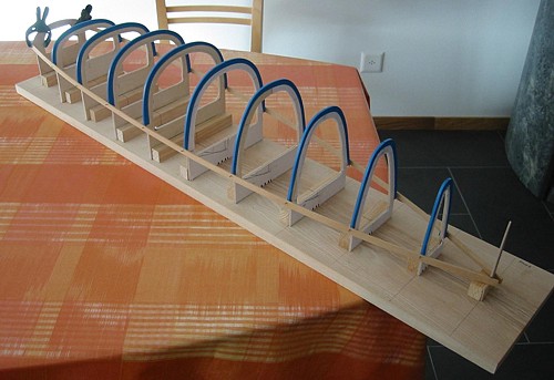
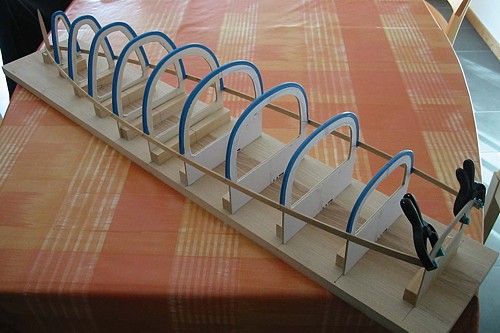
Jari sent me some pictures of tiller arms that he machined during the weekend.

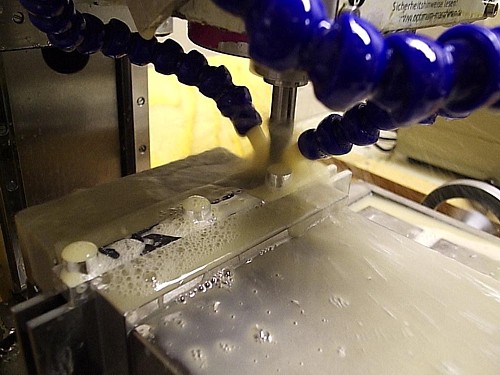
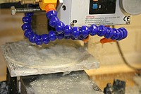
These parts need to be machined in three separate stages, here's stage 1 where the tillers are first roughed and then finish milled.

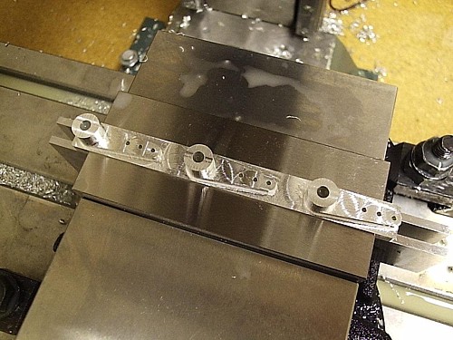
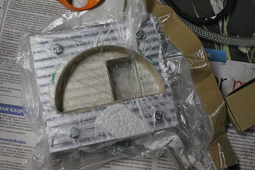
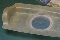
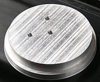
Here's what the parts look like after the first stage. After finishing the hole for the axle and three holes for the push-rod are drilled. In stage two the parts are turned 90 degrees and fixed using a jig. A hole can then be drilled and tapped for a set-screw that will tighten against the rudder axle.

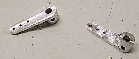
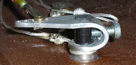
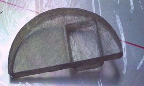
In stage three the whole thing is flipped over and the bottom of the stock material is machined off, which results in these completed parts.

These are still prototypes, for the Noux Mk2 I'd like to see two things: (1) assembly of the boat without tools, i.e. the attachment of the tiller arm to the rudder axle should not require any special tools (allen key, screw driver, etc.). This could be achieved with the current design simply by using a screw with a thumwheel. (2) a fixed relative position between tiller and rudder axle, i.e. when I attach the rudder I want to be sure it sits straight without having to check it everytime and possibly re-trim on the transmitter. A low-tech solution is to file or grind a flat part on the rudder axle onto which the set-screw pushes. If anyone has better ideas I'd be glad to hear about them !
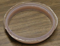
Update 2006 Dec 05:

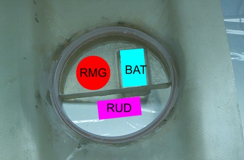
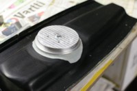
Johan Prak from the Netherlands sent me a picture of his homemade rudder fitting. A very simple design that anyone can make:

Noux Radio Installation

This is the shape and placement I finally settled on. Above is the mould, cnc milled from two 15mm thick pieces of aluminium bolted together. Very similarly to Craig Smiths Obsession I am going to mount the RMG winch on one side, and have a compartment for the battery on the other side. This is not the conventional way to do vacuum moulding, here I'm using only a bag, normally the laminate is followed by a release film, and the a breather (white fabric above), but I find all of this too complicated for small parts. Using just the bag works almost as well, an improvement is to use more of the breather around the laminate so the pressure spreads a bit more evenly. Vacuum bagging need not be high tech: the bag is a plastic bag used for selling fruit in a supremarket, and our pump is an old refridgerator compressor I got second-hand from a repair shop for about 5 eur...

Here's the finished part. Surprisingly stiff with three layers of 165g twill weave glassfiber - it must be all the shapes and angles that does it. Moulded with a vacuum bag (above) to ensure that the fibers follow all the 90-degree bends a bit better. In the picture the bottom of the battery compartment is still in place - the bottom will obviosly have to come off and I will fit some other support for the battery which is about 50mm deep. I didn't want to mould something that was a 50mm deep hole in one go, this part is hard enough to release from the mould as it is.

This is what the RC-tray looks like when mounted in the boat. Here we have first the pot-recess which is moulded into the aft-deck. Into that recess the rim of the rc-pot is pressed, and the rc-tray laminate fits into the pot-rim. I've indicated using colors and text approximately how the components are going to be installed. The tray will be fixed to the rim and deck using three M3 screws, which will thread into rivet-nuts that are epoxied to the aft-deck. The rudder servo will require its own mounting bracket - that's next on the design/build to-do list.

Temp controller for curing box

Curing epoxy mouldings typically requires elevated temperatures (+ 40 to 70 C) for 4-12 h. Previously we have done this in a cardboard box with a car-heater continuously blowing hot air into the box. By adjusting the number and size of holes in the box the temperature can be crudely varied.

Here's an attempt to create a better heater with temperature control.

Temperature controller with display and input buttons on the left. White temperature sensor in the middle. 200 W heater-blower box on the right.
Continue reading Temp controller for curing box