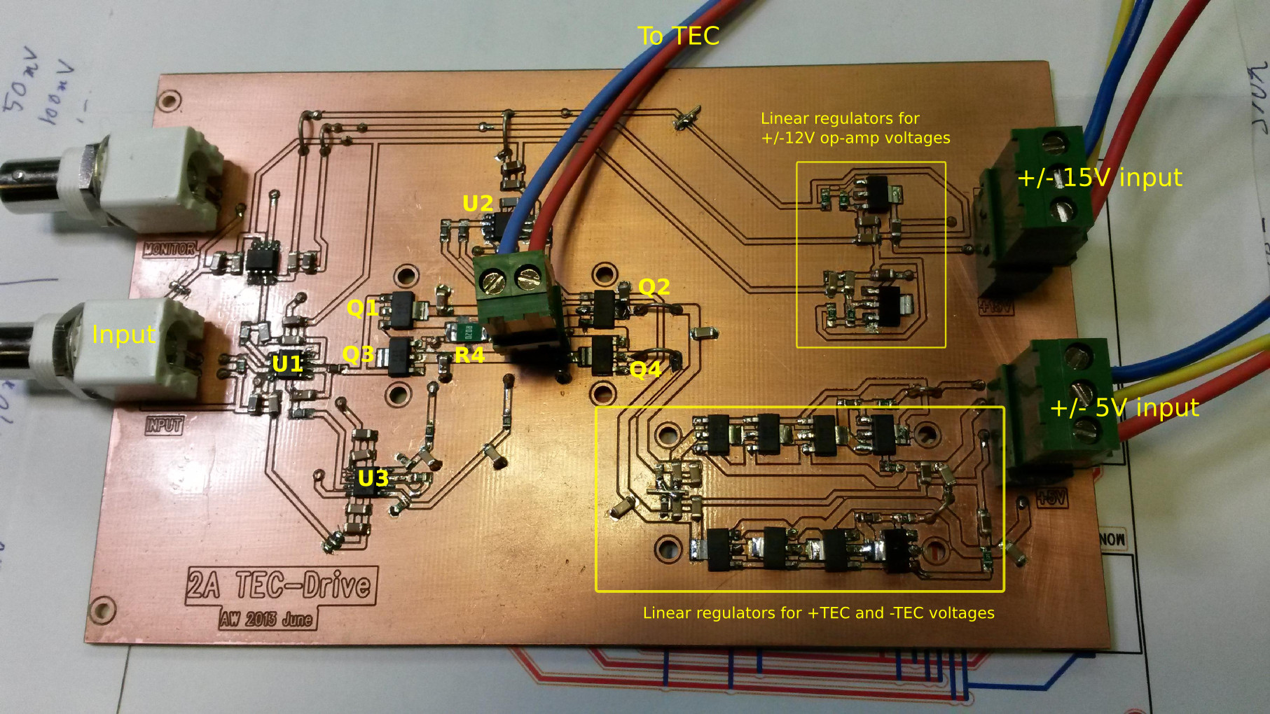
I've been assembling and testing this PCB over the past few days:

It's a linear +/-2 A voltage-to-current amplifier meant for driving a constant current through a Thermoelectric Cooler (TEC). The circuit is (loosely) based on a 2001 Burr-Brown/TI application note "SBEA001 - Optoelectronics Circuit Collection".
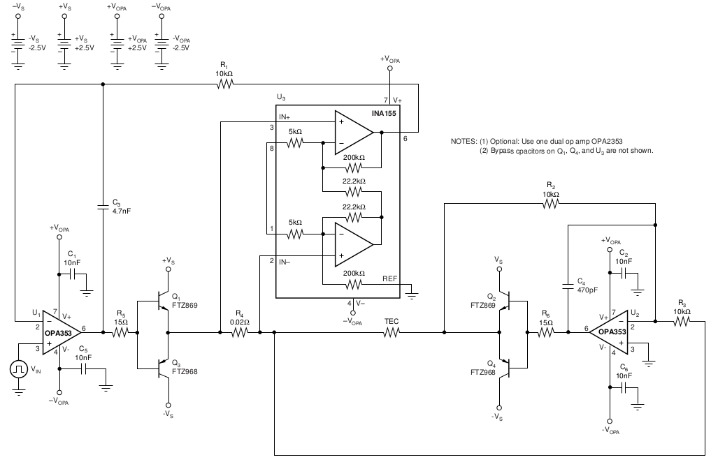
Description: U1 drives one half of the H-bridge (Q1 and Q3) based on a feedback signal which is the amplified (U3) voltage drop across a current-sensing resistor (R4). The other H-bridge half (Q2 and Q4) is driven by an inverting amplifier (U2) which forces the other end of the TEC symmetrically, inverted, to follow the output from U1.
Here's how these things look on the PCB:
After some assembly, bugfixing, and tweaking I measured a DC transfer function like this:
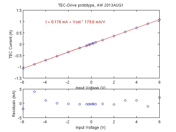
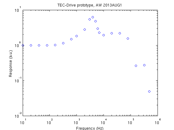
I am happy with the small offset of <0.2 mA and the linearity seems good. There is a rather large gain-error since the design-goal was 200 mA/V and the measured sensitivity is 179 mA/V. The AC frequency response is quite ugly with a high peak at a few kHz. In the time-domain this shows up as severe ringing when driven by a square-wave input. (aside: the SBEA001 application note shows a SPICE-simulated frequency response up to MHz frequencies - theory/simulation and practice differ a lot in this case!).
Things learned so far:
- The original design used OPA353 op-amps. I had assumed these will work with bipolar +/-12 V supplies and the output swing would be close to +/-10 V. Not so! (the OPA353 is a single-supply op-amp). I used TL071 op-amps instead and they seem to work.
- Bypass capacitors close to the collectors of Q1-Q4 are essential (but not shown in the circuit-diagram!). The feedback loop would go mad with oscillations without 1 uF caps placed close to Q1-Q4.
- Q1-Q4 (and the linear regulators) will require heatsinking for >1 A currents.
- The current-sensing instrumentation amplifier U3 (I used an AD8221 instead of the INA155 in the application note) is probably the most sensitive part of this circuit. I added 200 Ohm series resistors on the inputs, as well as low-pass filter capacitors (100 nF) to ground on both + and - inputs. This seems to have a calming effect on noise/oscillation of the feedback loop.
- This kind of push-pull power stage shows significant cross-over distortion when the input signal crosses zero. Here the op-amp that drives the bases of the transistors needs to slew quickly either up or down in order to turn off one transistor and turn on the other one.
If all goes well this TEC-drive will be part of a temperature control system consisting of about five different PCBs or circuits:
- Digital controller. Talks over SPI to DAC and ADC cards. Runs PID and/or feed-forward algorithm on real-time OS to keep temperature steady.
- ADC-Card. Reads +/-10 V input voltage at 24-bit resolution and 1-100 samples/s speed.
- DAC-Card. Outputs +/-10 V voltages as input to TEC-drive. 1 sample/s speed is sufficient.
- Temperature-sensor frontend. Converts pt100 (or alternatively 10k NTC) resistance change into +/-10 V output for ADC. Previous blog posts here and here.
- TEC-Drive (this PCB). Converts +/-10 V input from DAC into a +/-2 A constant current through the TEC.
Elegant and low part count. Very nice.
Notes to self, if a second version is to be made:
- align all transistors so they can be heatsinked with one big (standard?) heatsink. Or use TO-220 regulators with standard heatsinks.
- proper connector for output.
- add a trimmer for adjusting the overall gain. This prototype showed 20% less voltage-to-current gain than designed
- add a trimmer for adjusting offset errors to zero. This prototype showed +1.8 mA of current at zero input.
Hej Anders.
Thanks for sharing.
I'm in the process of designing a simple thermostated cuvette holder for our student spectrophotometers, based on a circuit from the same application note (the linear TEC driver-2). I want to use the DAC on an STM32 microcontroller for input, but I'm having problems getting my head around how to connect it. Would it be possible to get a copy of your circuit diagram?
Tusen tack. Esben
I can try to dig up the old PADS-schematic for this one. IIRC it follows quite closely the app-note.
I also made a 2nd version of the TEC-drive based on a high-current op-amp: http://www.anderswallin.net/2014/09/tec-drive-v2/
Thank you for the quick reply. I somehow missed the 2nd version of your TEC driver. I took a second look at the application note and it's quite clear to me how to connect the input when opamps are powered from a dual supply, but less so when it's a single supply.
I don't have PADS, so even if you did find the old schematic I probably wouldn't be able to open it. I will try and simulate the circuit in LTspice, hopefully that will answer my questions.