Yellow Submarine

We are finding that different colour pastes result in gelcoats with widely different ability to cover and produce a nice finish. This means we'll have to do a bit of experimenting and then only produce boats with colours that are easy to work with.

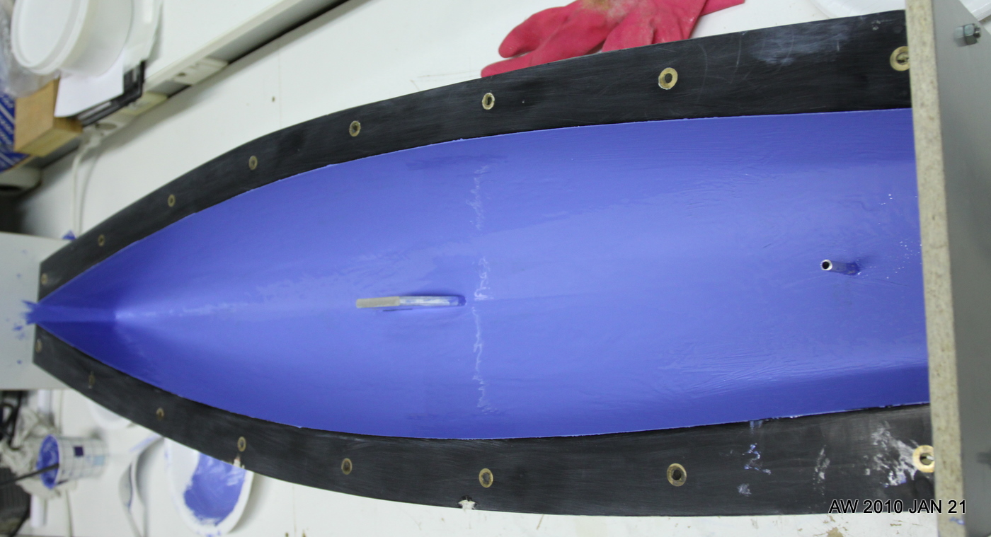
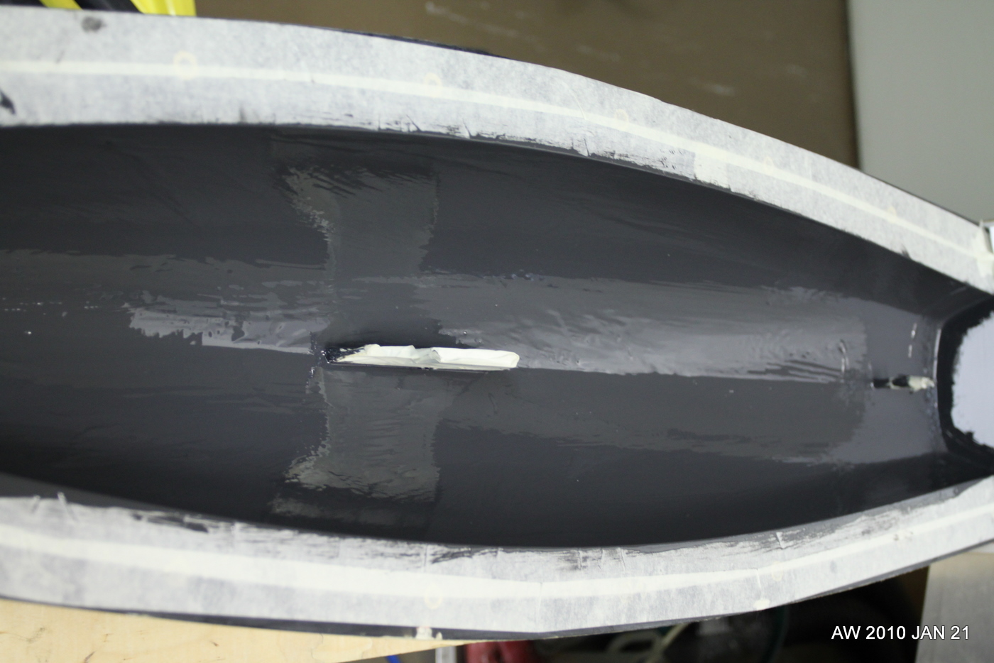
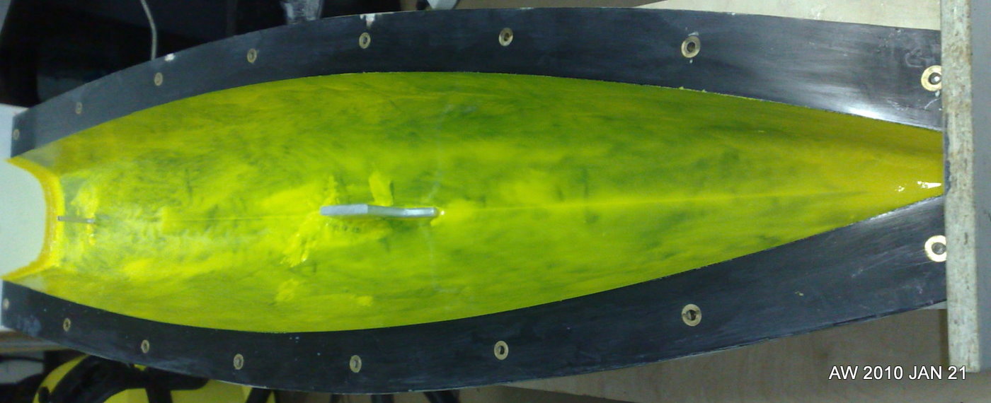
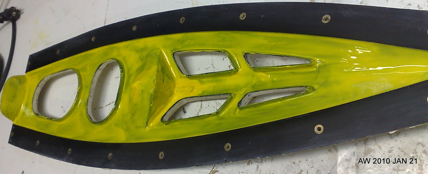
Hull nr. 3 "Yellow Submarine" was moulded last weekend and it will be interesting to see the result. Against the black of the mould-gelcoat the yellow doesn't seem to cover too well (compare to hulls 1 "sky-blue" and 2 "battleship-grey").

These pictures are taken just after painting the gelcoat into the mould. We make the gelcoat from the moulding-resin by adding colloidal silica and the colour paste.

Making hull nr3 was a 7 hour process:

10:00 arrive at workshop, do a bit of cleaning and preparation
11:00 start mixing and applying gelcoat to moulds, takes about an hour for deck and hull.
12:00 - 14:00 wait... gelcoat is in the mould and needs to cure. not much to do now(eat lunch, cut fibers, etc).
14:00 start moulding. The hull is fairly quick and only takes an hour or so
15:00 mould deck. This is more tricky with a lot of different small bits of fibers required, takes more than an hour usually
~16:00 fibers are in both moulds, close the moulds and start on the join between deck and hull
17:00 all done. Leave moulds and new boat to cure.

Connectors

Drilled four holes for AMP-connectors and used a hole-punch to make cut-outs for eight 25-pin D-connectors. The four motor-connectors will provide 3-phase power to the spindle-servo, the X- and Z-servos, and a high-speed live-tool spindle. The servos have three Hall-signals and three(single-ended) or six(differential) encoder signals which will enter the cabinet through the D-connectors. I'm using these since I'll use 25-pin printer-cables for the Hall/Encoder signals. There are eight D-connectors just to provide some room for expansion. Three will be in immediate use for the three servos, one for limit/home switches, and one or two will be used for a jog-pendant.  That still leaves three 25-pin connectors unused (tool-changer? tool-length probe? etc.)

Also mounted the breakout-boards inside:

Mesa 5i20 breakout boards

In 2006 I made optoisolator cards for the cnc-mill project, but now with the lathe I am using servo-drives and a VFD which mostly already have optoisolated inputs, so I will use these very simple breakout boards instead. There are two pitch-standards for the screw-terminals, an imperial one with a pitch of 5.08 mm (i.e. 0.2 inches), and a metric one with 5.0 mm pitch. These boards are for 5.0 mm.

Pads logic and layout files: 2010_01_16_m5i20_breakout_board

Etch-mask (PDF): etch-mask


Mast partner

Update: here is Jari's "fork" design for the mast-partner:

The forward hole could be made a bit bigger so a 4mm acetal-rod with a small central hole for the jib-sheet will fit. There could be an M3 or M4 threaded hole added for the mast-ram, and finally some holes for a U-shaped bent wire which forms a deck-eye through which the no3 jib is sheeted.

Here's the glassfiber version I was first thinking about:

The way we mould the deck and hull in one go we don't get an overhanging foredeck which would support the mast. One solution is this kind of "mast partner" which is glued/bolted to the foredeck and provides sideways support for the mast. If the slot is made say 16 mm wide the mast will need a sleeve of metal/plastic that fits this 16 mm slot accurately. There is room for a ca 18-19 mm diameter thumbwheel(red) on the mast ram.

Here's a photo of a SAILSetc 10R (or M?) which uses this idea:

Radio install idea v3

radio
Here's another idea for the PIKANTO radio-installation. The yellow parts are 1.5 mm glassfiber boards (PCB-material) which are glued to the finbox and the mainsheet post. They would provide two or four mounting holes for M3 bolts that secure the main radio-plate (not shown) to the boat. If this is rigid enough I think no support to the sides of the hull or to the deck is required.

Jib support mould

fokkatuki
This jib-support part which goes into the bow of the boat has about three or four different purposes. First, it stiffens the forward deck to take the loads from the rig, second it provides a 6 mm i.d. tube for a dyneema-thread type no1 rig swivel, third it provides a 3mm wide slot for recessed steel pins for the no2 and no3 jibs, and fourth it holds a block for the sheeting system. Here I'm trying a home-made block made from a 24 mm diameter 3 mm wide acetal-wheel (yellow) which is designed to rotate around an M2 bolt through the sides of the shaped jib-support.

Lester Gilbert's PIKANTO-page has pictures of how the SAILSetc equivalent parts look like. With an RMG winch there is no need for the 1:2-gearing in the sheeting-system, and a block is placed at the very front of the boat (see SAILSetc part 67RMG).

SAILSetc has a downloadable drawing with the sheeting systems: http://sailsetc.com/downloads/2006/67G.pdf

Jari has cnc-milled the positive moulds for this part:

IMGP1913-1
Stock is a 200 mm length of 100 x 10 mm aluminium bar. There's a  2 mm hole in the moulds for the block-axle.

IMGP1909-1

Next follows the negative moulds.