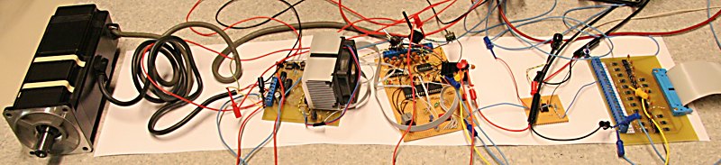
Today I got the whole motion control chain from EMC2 on the pc through the Mesa m5i20 servo-card, homemade optoisolator card (far right), PWM to analog filter (small board on the right), servodrive (middle), powerstage (middle left, with heatsink), through to the motor (left, a Sanyo P5 1kW servo) working !
This is truly Open Source cnc: EMC is obviously an OpenSource project, but also the FPGA configuration on the m5i20 is published under the GPL, and my servodrive code will be available when it fully works.
The picture might seem messy with a whole lot of wires - but I can assure you that it's all very organized... 🙂
 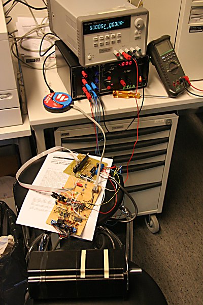
I actually got the servodrive working, in the sense that it was spinning the motor, a few weeks ago but did not have time to blog about it then.
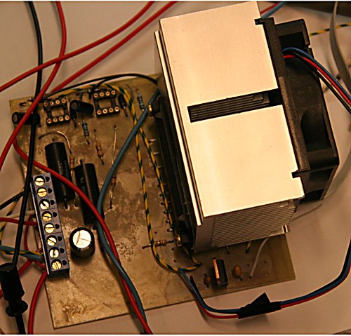
Here is the setup from 28. May. Motor in the foreground, then servodrive, then powerstage which at that point did not have the heatsink+fan. The logic +5V and the +15V that the powerstage logic requires is taken from the fixed outputs of the lower powersupply. The upper powersupply powers the motor, it only goes to 50V so I am not reaching full rpm or power, but this is enough for testing. No-load current drain seems to be as low as 0.2 A for the 1 kW motor.
Â
Â
Â
Â
Â
Â
Â
Â
Now let's take a look at the boards in the chain from the top picture:
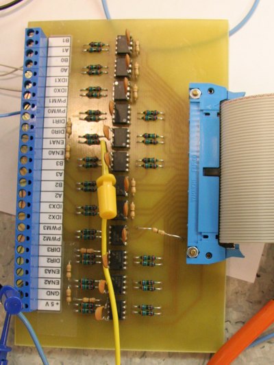
This is an optoisolator card for the 50-pin ribbon cable from the m5i20 pci-card. It has 12 HCPL2630 two-channel optoisolators, six configured for the outputs, and six for the inputs. This connector from the m5i20 has the motion control signals, so for each axis there is an encoder input (A, B, Index) and a DAC output (PWM and DIR). There's also an amp-enable signal for each axis. If you look closely you can see that I forgot the decoupling capacitors (100nF ceramics between Vcc and ground), so I had to solder them directly to the IC legs... well it's supposed to have a home-made feel to it anyway !
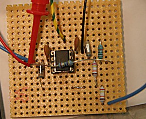
This small test-board filters the PWM output from the m5i20 to an analog voltage between 0 and 5 V which will be used as a speed command for the servodrive. It's a two-pole VCVS filter with a designed -3 dB frequency of 5 kHz and uses a TL071 op-amp (copied the design from Horowitz & Hill). I will need four of these for the mill. A bit of a hassle is created by the fact that the op-amp needs bipolar supply voltages, in the test setup I used +/- 12 V.
The informed reader will at this stage note that it is somewhat dubious to first have a digital servodrive card that outputs 0 or 5 V digital signals, then output a speed command using PWM with this card, filter it to smooth it out into an analog voltage, and finally digitize it in the servodrive back to a digital number.
A smart way would be to use some kind of fast serial digital protocol between the m5i20 and the servodrive to directly transfer a precise digital speed command to the servodrive. However life is short and at this stage I don't feel like I have the time and energy to learn how to program the FPGA, come up with a good protocol, program the dsPIC to receive this protocol, and finally test, debug, and re-test the implementation. So an analog voltage command will have to do for now. I'm hoping it will not degrade the overall performance of the servo system noticeably. If anyone has any comments on this I'd be glad to hear them!
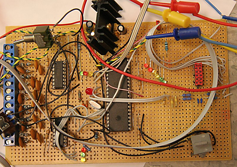
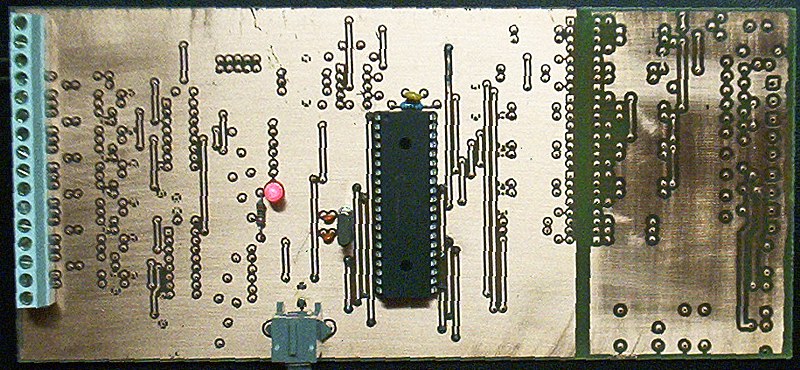
Then comes the servodrive itself. I chose the Microchip dsPIC30F3011 because I had some previous experience with PICs, and the dsPIC included encoder and pwm-generator peripherals on-board. Differential encoder and hall signals come in at the left. They are filtered and converted to single-ended signals by two DS3486 ICs (Quad RS-422/423 Line receiver) and then fed to the dsPIC. Otherwise there is very little interesting on this board. A regulator at the top provides +5 V, LEDs in the middle (Encoder at top, status in the middle, Hall at the bottom) show the inputs to the drive, and LEDs at the right (45 deg row) show the PWM output signals. I program the dsPIC with an ICD2 through the modular jack in the right bottom corner.
Finally the powerstage. This is an International Rectifier IRAMS10UP60B. I've mounted a heatsink and a fan, probably meant for a P4 processor, which means I can run the drive as long as I want without overheating the powerstage - at least for now when there is no load on the motor. At the top there was a place for current sensing amplifiers (the black big cylinders are current sense resistors), but now I think it makes it unneccessarily complex to have current sensing in the servodrive so I am probably going to omit that in the next version.
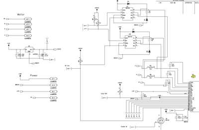
The IRAMS powerstage requires very few components around it to work. Click the schematic for a pdf file.
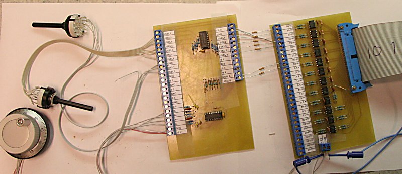
Another thing I've been hooking up to the m5i20 is a jog-pendant. It will feature a jog-wheel (left bottom. Micronor 100ppr from ebay), one three position rotary switch (left middle) for selecting the jog-increment 0.1/0.01/0.001 mm, and one six position rotary switch (left top) for selecting jogwheel function (X/Y/Z/FO/RPM/?). There will also be push-buttons for speed-hold, program step, spindle on/off, and coolant on/off. The jog-pendant is connected through another 50-pin cable to the m5i20, again optoisolated (rightmost card), and to reduce the number of IO pins I've decoded the differential signals from the jogwheen with a DS3486 to single-ended signals, and I've encoded the state of the six-position rotary switch into a three-bit value with a 74HC148 (8to3-line priority encoder).
Â
Update 2006 June 14:Â
Mk 2 has just passed the obligatory blinking-LED test:
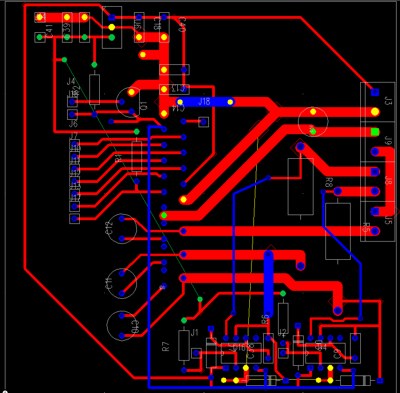
Mk2 integrates the powerstage and microprocessor one one 'long-eurocard' (i.e. 100x220mm pcb). I've also included the pwm to analog filter, and I got a bit scared by the amount of noise the powerstage generated - so the powerstage is now optoisolated (division-line at the right). The board is now populated with the bare minimum that the dsPIC needs: a Crystal with two small caps(center left), a pullup resistor for MCLEAR (top), and a decoupling cap for Vcc (top). The ICSP programming socket is the grey thing below/left of the dsPIC.
Hi etla,
looks very cool, I am working on a simalr project for my 300watt versions of the same motors.
I am interested in the powerstage for your motor. Are you using the circuit from the irams datasheet?
Perhaps you could post a link to the schematic. Catch you later on #emc
cheers
Really cool
Hi Lawrence,
There are now two more pics with the schematic and the pcb for the powerstage. If you click the schematic pic you can download a pdf schematic.
Great Work! Can you please upload whole schematic and PCB in zip? And please include the references in it if possible.
Thank you in advance.
Hi Jitesh,
The schematics, PCB, and software for Mk2 of the servodrive will be available when I have had to improve the software to do sinusoidal commutation and test that it really works well with EMC and the Mesa servocard. It might take a few weeks.
Anders
could the solution is used with the Brushless AC Servo Motor 100W?
H Trungsy,
As long as your servo motor has Hall sensors (three TTL signals, either single-ended or differential) and a quadrature encoder (again either single-ended or differential), it should be possible to use this drive.
You will need to check what voltage your motors are rated for and build a powersupply accordingly. The powerstage is rated for a very high voltage (600 V I think) so there should be no problem there. Choose a powerstage (6/10/16 A) according to how much current you need.
There is no current-feedback in the drive yet, only overcurrent protection which will shutdown the drive at the rated current.
I have been busy with other things but the idea is to publish Mk2 real soon now including code for encoder based sinusoidal commutation.
AW
Hi Anders,
Great effort, I was interested in your comment of how noisy the Irams units are. I also have a Servo drive here under development and have the same concerns, I have now fitted low esr bus capacitors (on board with the Irams module) and am currently playing around with snubbers on the Irams outputs. Like you I will also optically isolate the drivestage as even though my motion control communications are Rs485 noise is still a concern. Once again great effort and keep up the good work.
Kind Regards, John Kooloos
Hi John,
I'm afraid I don't know very much about EMI shielding and noise in power circuits. My mk2 boards seems to work OK although looking at the control signals (an analog voltage + a TTL dir signal) with a scope there is a visible difference between having the powerstage on/off. A glitch appears everytime the pwm swithces, i.e. at twice the PWM frequency. I am hoping that perhaps additional analog filtering or digital filtering of the analog command will solve this problem.
Can you tell me more about the chokes you are using ?
On the mk2 board the biggest cap I have on the DC bus is 10 uF and then there are about five caps with about 5-10x step down in capacitance for each one. I don't know very much about EMI filtering but this was suggested to me as a rough rule of thumb.
I have not looked at the encoder/hall signals with a scope, they are differential and did not seem to suffer very much...
John, looks pretty good. i am using the m5i20 card also with emc2. i am also using mesa 7i33 card to do the pwm to +-v signal. it takes the first 50pin (P2) cable directly from the m5i20. unfortunately it does not have any optoisolators so i am quite interested in yours opto board. i wish to opto all the on/off type io's. i am also very, very interested to see your jog pendent setup. it looks like in the photo that you are again through an opto board. which of the m5i20 50pin headers is that hooked up to? number 3 (P4)? anyway, good luck.
Hi Noel,
When using the m5i20 in the Hostmot-4 configuration (the one that comes with emc2) the motion is on one 50-pin header (i think P2), and the two others are identical (P3 and P4), 8 outputs and 16 inputs per header.
So it makes little difference to which header the jog-wheel is connected, there's just some modification to the HAL scripts neccessary.
The jog-wheel ofcourse consumes only inputs, 2 for the wheel, 5 for the two selector switches, and 4 for the pushbuttons, that's 11 in total which still leaves the 8 outputs and 5 inputs free on the header used for the jogwheel.
I've got the HAL script for jogging X/Y/Z with a varialble increment 0.1/0.01/0.001mm ready.
I still want to be able to adjust feed-override, Alex Joni says it will be in halui "real soon"...
Then I want to adjust spindle rpm with the jogwheel also, that will go through the iocontrol pins also.
When those two additions (FO and spindle) start working my plan is to post a blog entry with some pics of the complete jog-pendant and also the HAL script.
The optoisolator boards are fairly simple, I'll post some details about them when I get the mk2 servodrive working properly - hopefully it won't take many weeks from now.
Anders
thanks for the quick reply. any chance i could use your schematic for the opto board you use on the io 50 pin connection? i am pretty much strictly mechanical, so electrical/electronics are difficult at best. i've tried doing an opto schematic, but i am not sure if it is worth the paper it's on.
The optoisolators are now described at
http://www.anderswallin.net/2006/08/optoisolator-cards-for-mesa-5i20-servocard/
Anders,
Is it possible for you to send me or publish on your website your HAL
files. I am particularly interested in how you have done your jog box.
Thanks,
Dave.
Dave,
It's been a long time since I've done anything to the servodrive and/or the jog-wheel. I'll try to dig out the jog-wheel HAL for you and post it here as a comment.
AW
Dave,
some notes, text, and a HAL file for my jogwheel now at:
http://www.anderswallin.net/2006/11/jogging-emc2/
Hi ,
I do not know much about cnc servo control,so I want to see complet schematics for cnc servocontrol using PC ( step/direction) driving software.I will try to create cnc mill,I am not setisfied with stepmotion.
Regards,
Alex
Hi Alex,
I don't have a complete schematic for step/dir servo control. Tero Kontkanen is working on something like that, but as far as I know his project is not open-source. see: http://www.students.tut.fi/~kontkant/servodrive.php.html
I found the motor control tutorials at http://www.microchip.com quite useful, if you don't know much about motor control you should probably read them.
AW
Thank You Anders for usefull info.
Alex
Hello, interesting project, congrats!
otherwise for capturing a PWM signal on a PIC you've got capture/compare inputs 😉
No need for a analog pin input.
Max
Hello..
im trying to program a dspic30f3011 with an icd2 but its not recognising the chip .is there a way to program them.please do reply or email me please
dear.anderswallin
i want to know did u finish this project and software for dsPIC brushless
servo .
if so where can i get it
great thanks
sherif
I never did finish this project...
With the prototype I got the motor to spin in both directions and also to respond to external pwm/dir commands.
The software was in C for the dsPIC and was based closely on the similar application note from Microchip. I think you are better off by starting from the Microchip example code rather than looking at my buggy code.
IT IS A GOOD PROJECT AND I ALSO DOING A DS30F3011 BASED MOTOR CONTROLLER PROJECT CAN YOU UPLOAD A CODE FOR ENCODER INITIALIZATION ..........
THANKS
Sorry I don't have any code left from this project. You should consult the microchip application notes, they are usually quite good and I am sure there is example code for the encoder.
Hi ,
Could you please share your code for dspic3011, I am also trying to build a small home CNC.
Thanks
saneesh
Sorry I do not have the code for this project available anymore. It was closely based on Application Notes from the Microchip website - you will be able to find code for PWM-generation, 3-phase commutation, and PID-loops in the application notes.
Anders
Hi ,
Could you share the filters used in input capture pins , did you used any Hardware buffers for this.
Since the low speed velocity estimation is very annoying. also how you are deriving feedforward velocity from quadrature signals from Linux CNC.
Rgds
Saneesh