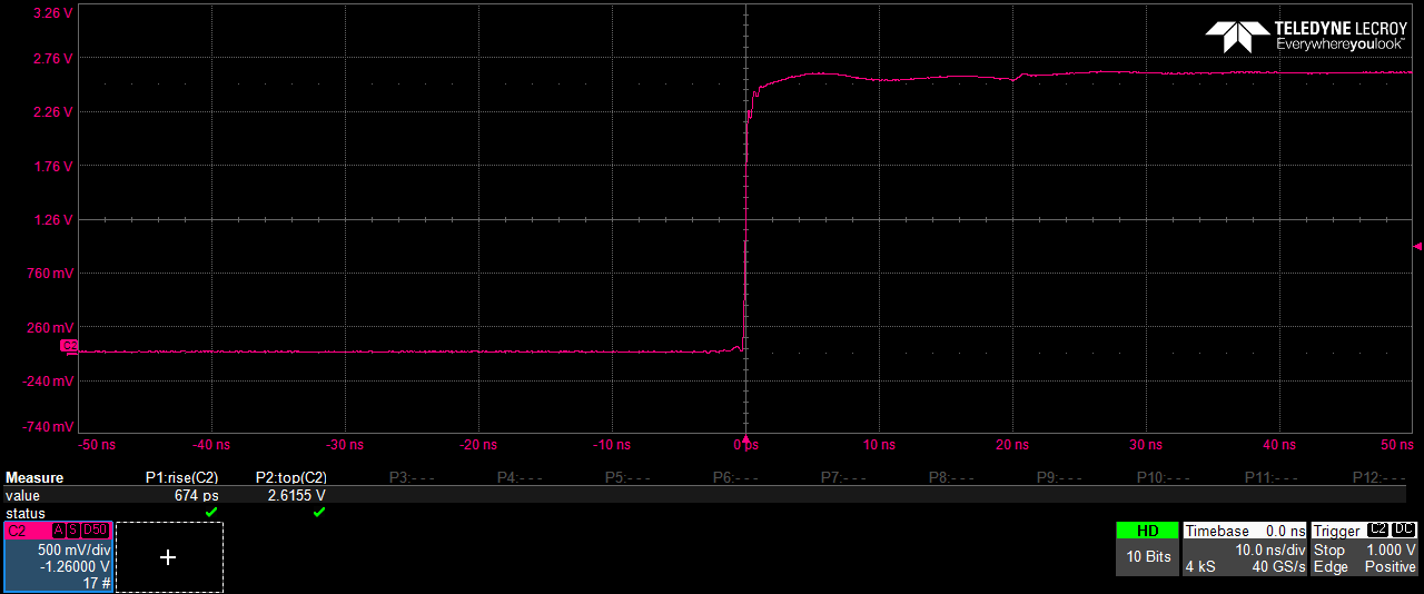
With a longish BNC-cable between a PDA-output and a 4 GHz oscilloscope we see a 10%-to-90% rise-time of <700 ps.
With a longish BNC-cable between a PDA-output and a 4 GHz oscilloscope we see a 10%-to-90% rise-time of <700 ps.
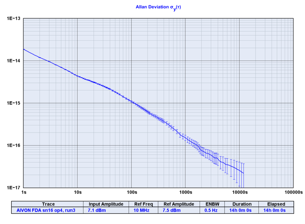
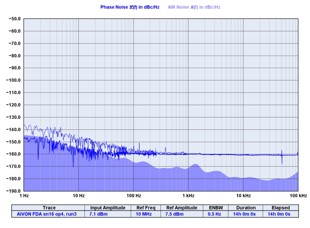
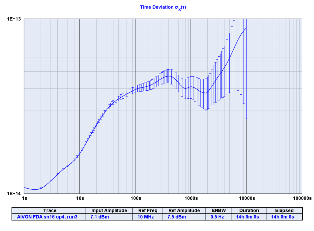
Update2: Here's the 14-hour data together with a 14-hour noise-floor run. The ADEV and TDEV results are more or less instrument-limited. Only for phase-noise above 100Hz offset is the instrument floor significantly below the result for the distribution amplifier.
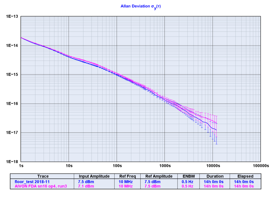
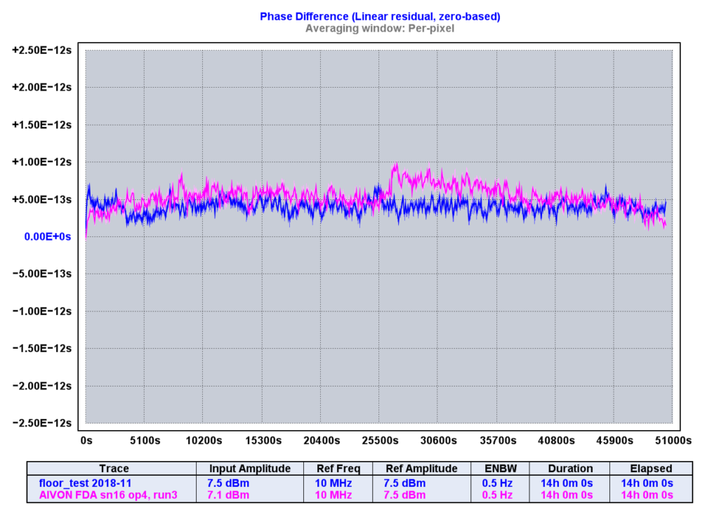
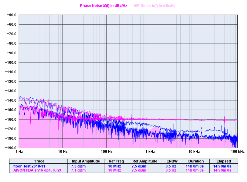
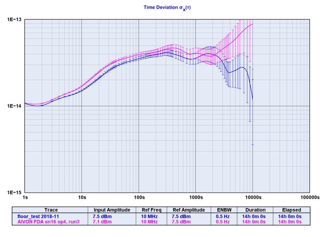
Update: Here's a 14 hour run of the residual phase noise, ADEV, and TDEV, as measured through the frequency distribution amplifier. Instrument is a Microsemi 3120A phase-meter.
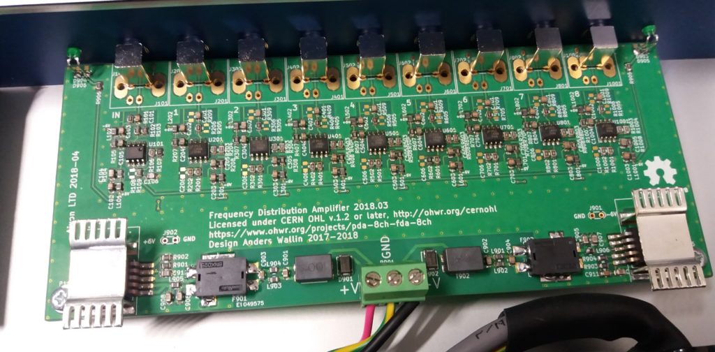
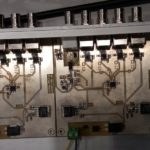
Aivon has now produced around 16 of these distribution amplifiers.
There's a new op-amp which might be interesting to try for the FDA board: THS3491. It has a grounded pad under the op-amp, so we need a new EP-variant of the PCB.
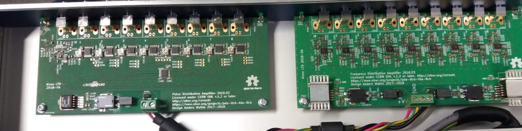
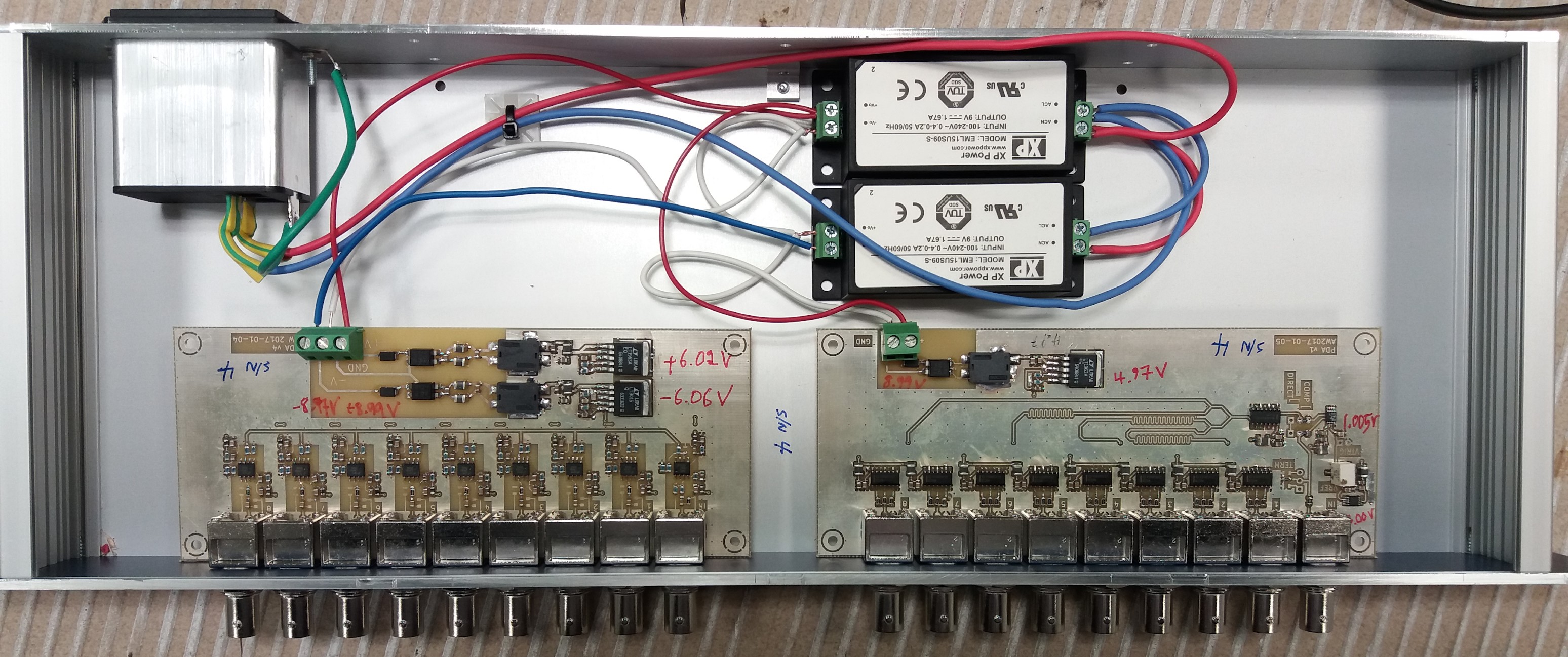
My open-hardware design for a 1:8 pulse and frequency distribution amplifier is now available from Aivon LTD.
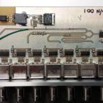
For isolated 1PPS distribution I made this distribution board.
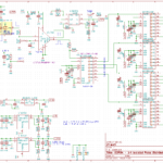
The input is a TLP117 (or similar) optoisolator driving a LT1711 comparator with a 1.0 V trigger level. An output LED-blink is provided by LTC6993. Outputs are driven by IDT5PB1108 buffers.
In jitter measurements with a HPAK 53230A counter the jitter between two 1PPS pulses (from masers) seems to degrade slightly through this amplifier: from RMS 16-19 ps directly on the maser-outputs to between 21 and 26 ps RMS from the outputs of the ISOPDA. Maybe a faster optoisolator would be better?
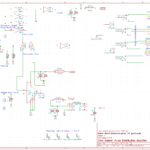
KiCad sources available on request.
Despite length-matching traces between a distributor-stage and the individual output-stages on my pulse distribution amplifier there remains a 2-300 ps peak-to-peak output skew between the channels.
Here's a test where a 50 pF or 10 pF trimmer-cap is added just before the input of the output-stage. I found that tuning the cap results in a variable delay of 60-80 ps/pF, so if initially the channels are within 300 ps of each other the 500 ps tuning-range of the 10 pF trimmer-cap is sufficient.
As a test I first tuned all channels to within 20 ps peak-to-peak, then verified this the following day and got 52 ps peak-to-peak. BNC-connectors might not be the greatest for picosecond level repeatability.
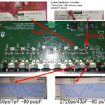
Here is the measured output delay skew from four of my "PDA 2017.01" designs, based on LT1711 comparator driving a 74AC14 schmidt trigger which in turn drives eight 74AC04 output-stages.
Also included is my earlier measurement of an Ettus OctoClock.
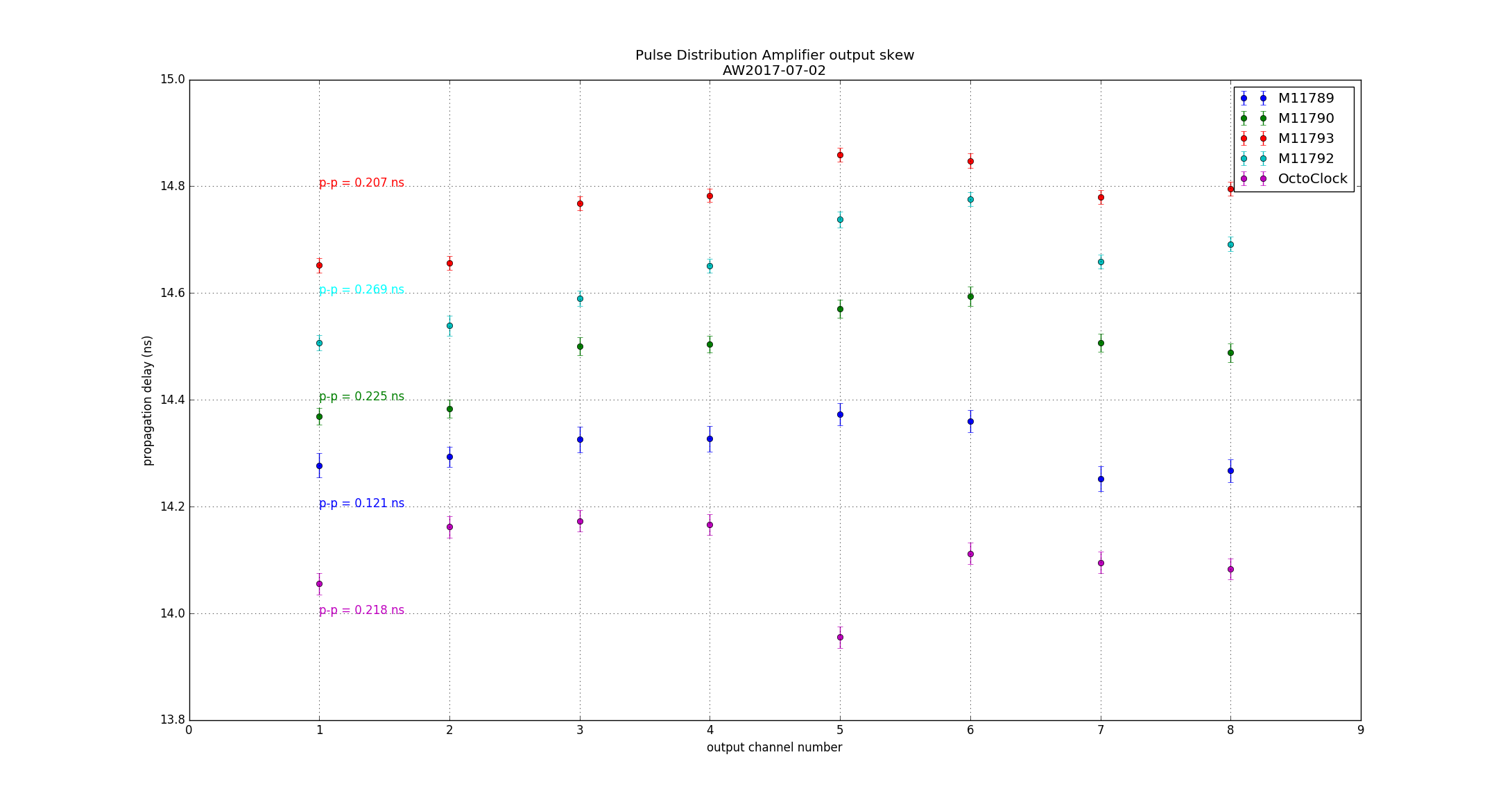
Although the PCB was designed with equal-length traces for the output stages it appears that channels 3-4 and 5-6 are consistently late, and some shortening of the traces would improve things. I tried this on one PCB (blue data points) with moderate success.
Measurement setup: 1PPS source to 50-ohm splitter. One output of the splitter drives CH1(start) of a time interval counter (HPAK 53230A), the other output drives the input of the pulse distribution amplifier. Outputs wired to CH2(stop) of the counter and measured for 100 s or more (delay is average of 100 pulses). Counter inputs DC-coupled, 50 Ohms, trigger level 1.0 V.
Assembled another distribution amplifier today. S/N 004. Measurements to follow at some point.
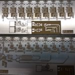
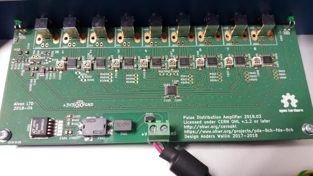
A new pulse distribution amplifier for 1PPS distribution.
The input is fed to a LT1711 comparator triggering at 1.0 V (set by reference ADR423). This edge is buffered by 74AC14 before 1:8 fan-out to output-stages with three 74AC04 inverters in parallel driving the outputs.
Preliminary measurements show around 200ps channel-to-channel propagation skew - to be improved on by further trace-length matching or tuning. More measurements to follow.
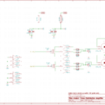
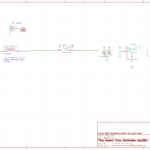
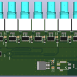
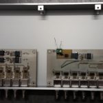
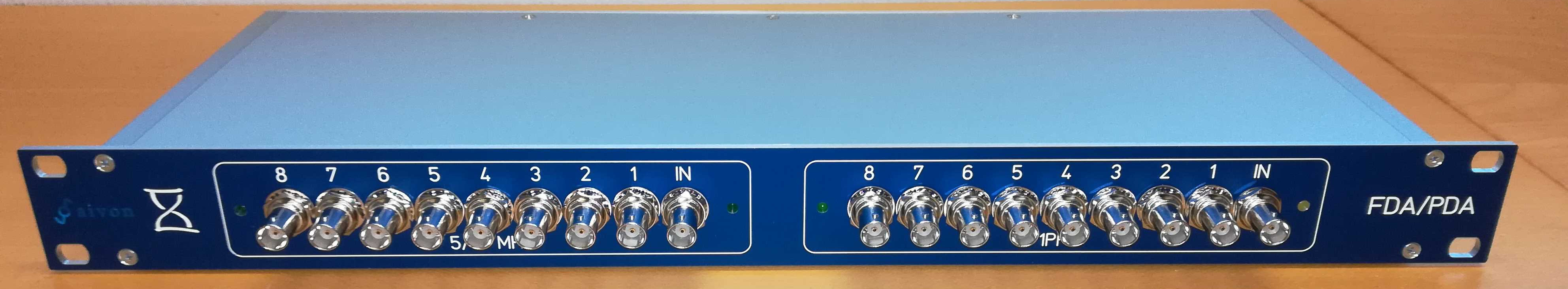
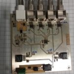
A new distribution amplifier design featuring a 1PPS pulse distribution amplifier (PDA) and a 5/10 MHz frequency distribution amplifier (FDA).
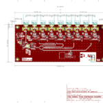
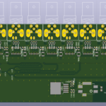
1U 150mm deep rack-enclosure from Schaeffer. Prototype PCBs without soldermask or silkscreen from Prinel. Both the FDA and PDA boards have 1:8 fan-out with 9 BNC (optionally SMA) connectors spaced 16mm apart. The boards fit comfortably side-by side on a 19" rack panel. Some funky BNC-cables with unusually large connectors may not fit side-by-side 16mm apart - a price to pay for the compact design. The plan is to use an +/-12 AC/DC brick power-supply (not shown) which fits in the back of the enclosure.
Detailed posts on the PDA and FDA boards to follow.