Lathe electronics

IMG_0764

Most of the electronics I've ordered for the lathe has arrived by now. Still waiting for the servo-drive for the main spindle.

Bottom left are three switched-mode power supplies: 5V 3.5A (logic etc), 12V 3.3A (brushless amps, E-stop chain, etc), 24V 1.3A (spindle brake)

Bottom right are two Chinese 350W 48VDC 7.3A power supplies for the X- and Z- servos. Bought on e-bay from one of the Chinese sellers that has free worldwide shipping, and these were not caught by the local customs, so I paid around 28 euros/supply!

Mid row: on the left a Siemens Micromaster 420 0.37 kW VFD which will be used for a future live-tool spindle, and on the right two pico-systems brushless servo-amps.

Top: limit switches, Mesa 5I20 PCI-card, 180W Brushless servos for X and Z, CUI encoders, Amphenol connectors.

Spindle servo encoder shaft

enoder_axle_before

The 1.75kW spindle-servo for the lathe only has resolver and hall-feedback. So I need to mount an incremental encoder with index pulse on it myself. The rotor for the hall-sensors attaches to the main motor shaft with an M6 bolt. Here I'm making my own M6 bolt with a long 'head'/shaft that will extend outside the back lid of the motor. I cheated a bit by starting with a 0.5" rod which already had an internal M6 thread. An M6 set-screw will form the bolt-part of the shaft, and is also used here to hold the part in the lathe. This was then turned down to ca 11mm to fit the hall-rotor, and 8mm for the part of the shaft that extends outside the motor and to which the encoder will mount.

Encoders are on order from digikey so they should arrive next week.

encoder_axle_after

By taking it slow and measuring a lot the 1949 Schaublin makes parts with tolerances approaching 0.01mm!

Spindle servo Hall-signals

motor_back resolver_and_hallsensors rotor hall_1 hall_2

Figured out the hall- and resolver-signals on the spindle servo today. There are two scope-pictures but the hall signal corresponding to the third phase is also OK, I just didn't save the screenshot. The pinout seems to be:

1: resolver a+
2: resolver a-
3: resolver b+
4: resolver b-
5: resolver c+
6: resolver c-
7: Hall A
8: Hall B
9: Hall C
10: +5V
11: GND
12: PE/case-ground

The Hall outputs require pull-up resistors, this test was with 1 kOhm resistors. If I install a normal A/B/Z encoder on the motor myself I should be able to drive it with a stock standard Brushless servodrive.

Lathe Spindle and Z-rail measurements

(the dial indicator reads in metric, with 1um resolution)

radially the spindle chuck-flange shows ca 14-15 um of runout.
Axially there is more wobble, ca 20um.

The Z-rails are very accurately aligned in the X-direction, I measured ca 6um error.
Measuring in the Y-direction, there seems to be a 40-50um jump around 10cm from the chuck. I'm not sure if that is important, since the rail-blocks don't make contact with the rail top surface. I think I need a way of measuring this again with the machine assembled.

Lathe spindle servo

info art-nr power-connector brake back-open U_V_W enc-connector resolver

A closer look at the spindle-servo today. Googling for the model number does not immediately yield a datasheet, although I found a few similar-ish model numbers. The high-power connector is simple with U, V, W phases, Protective Earth, and +/- terminals for the solenoid brake. The brake opens at 24V and 0.67 A. The back can also be opened but doesn't reveal much more than an October 2001 manufacturing date. Hooking the scope to U, V, W and rotating the shaft with an electric drill produces some nice sine-waves. I'm not at all sure about the pinout of the encoder-connector, but looking at pairs 1/2, 3/4, and 5/6 seems to give something that could maybe be a resolver?

JHQ Lathe

I've bought a cnc-lathe!
Well, it's not complete, more of a cnc-lathe project.

A fellow Finnish cnc'er "JHQ" started this project a few years ago, but as he now has a 5000 kg professional cnc-lathe and his own company, he hasn't had time/money to complete this project. There are many project logs out there with details of how the machine was designed and built:

http://cnczone.com/forums/showthread.php?t=27031

http://www.cnc-tekniikka.com/CNC-forum1/index.php?topic=121.0

http://www.robosota.fi/foorumi/viewtopic.php?t=935

http://www.devonparkour.com/ukcnc/forum/viewtopic.php?f=6&t=9

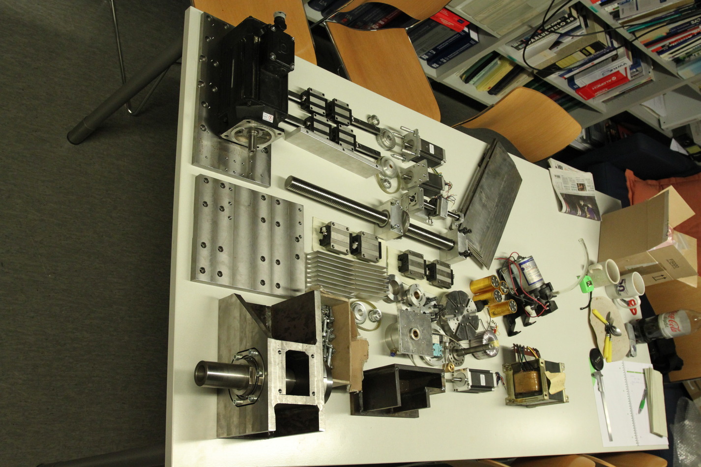
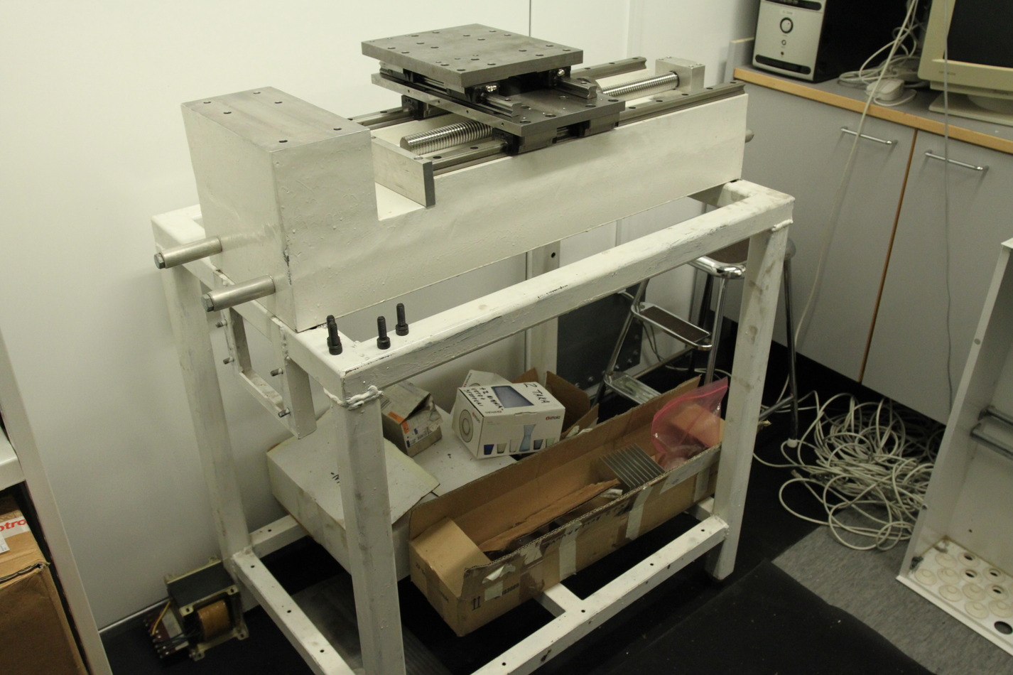
Some notes of my own, as I unpacked everything today.

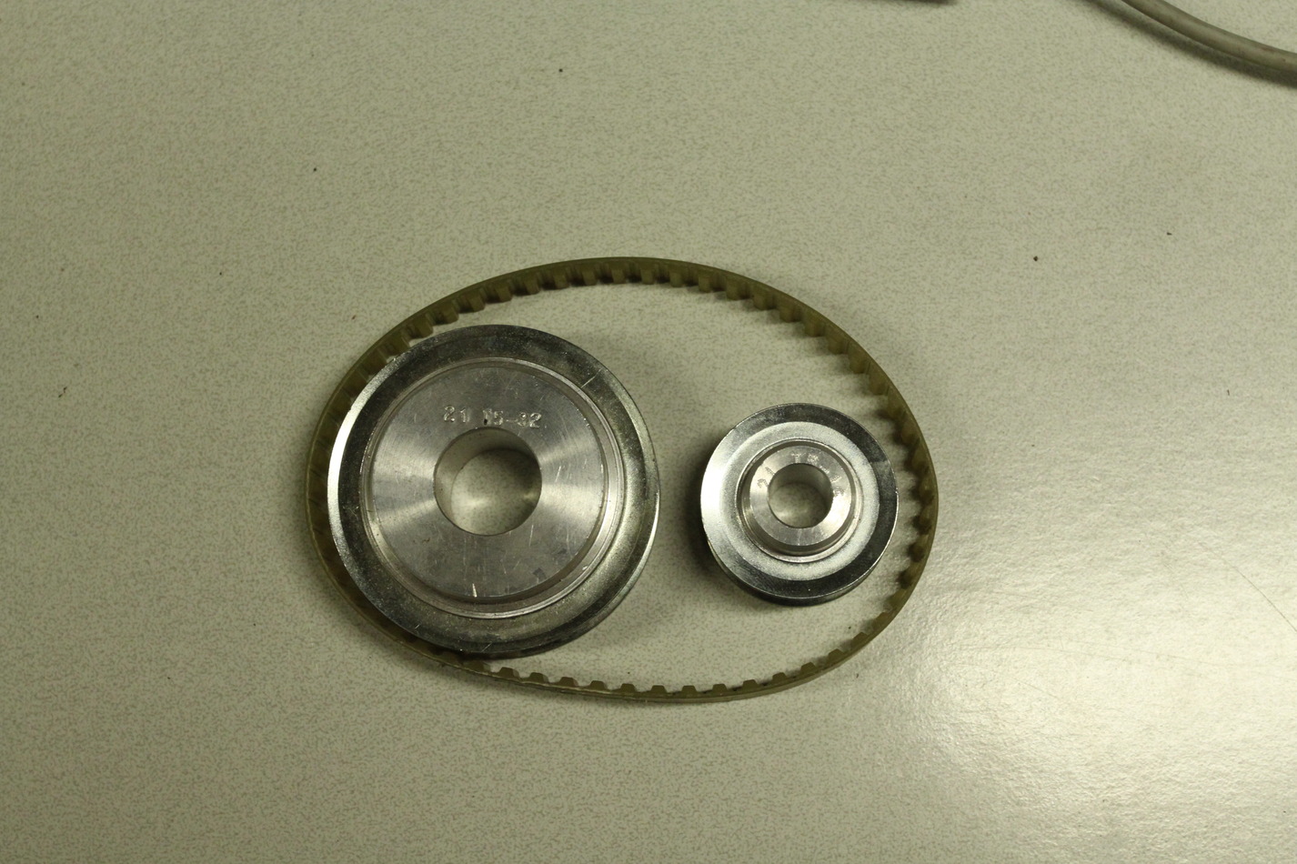
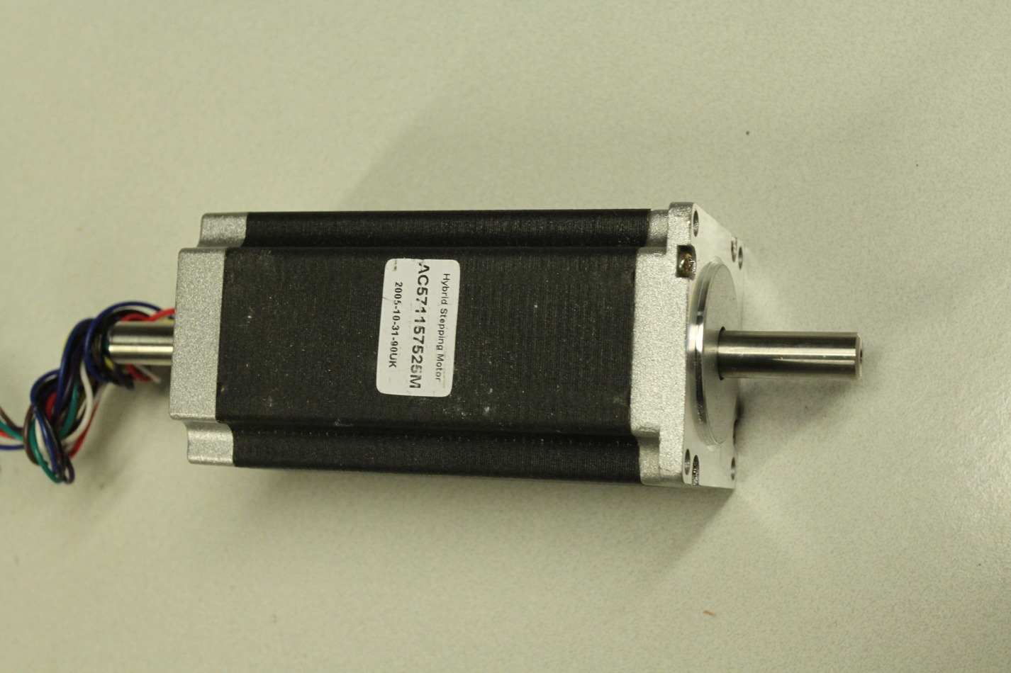
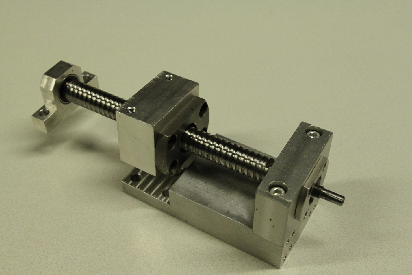
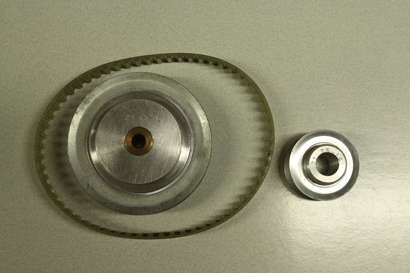
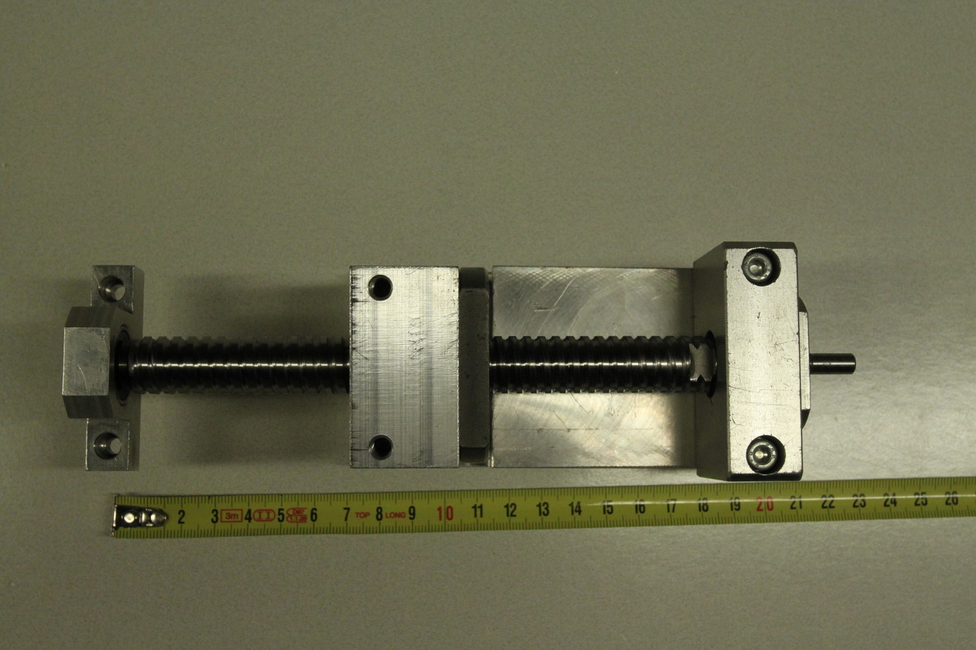
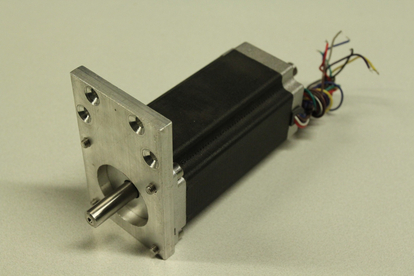
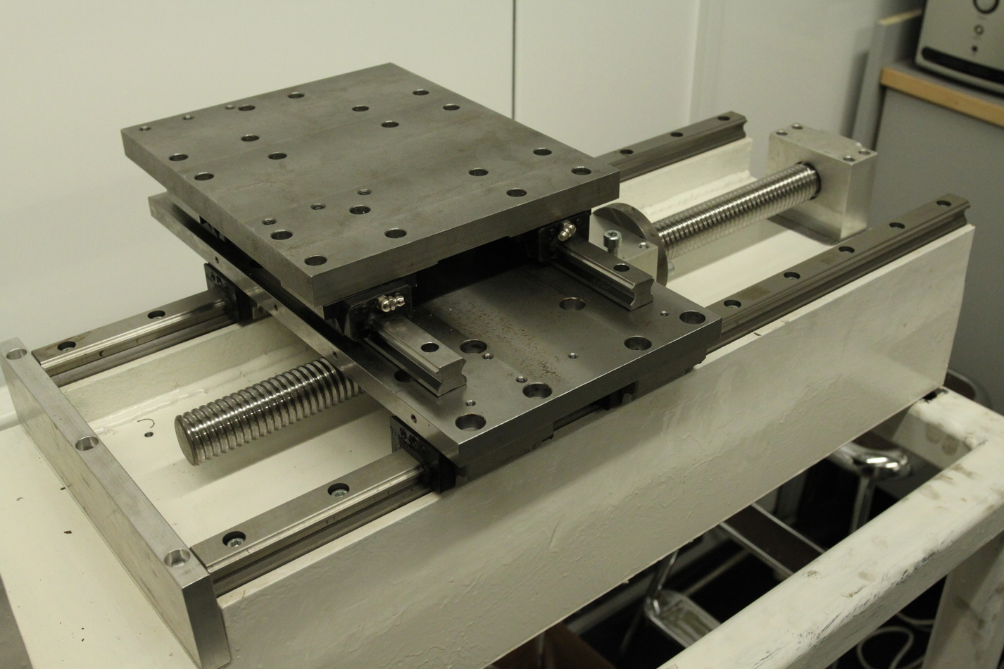
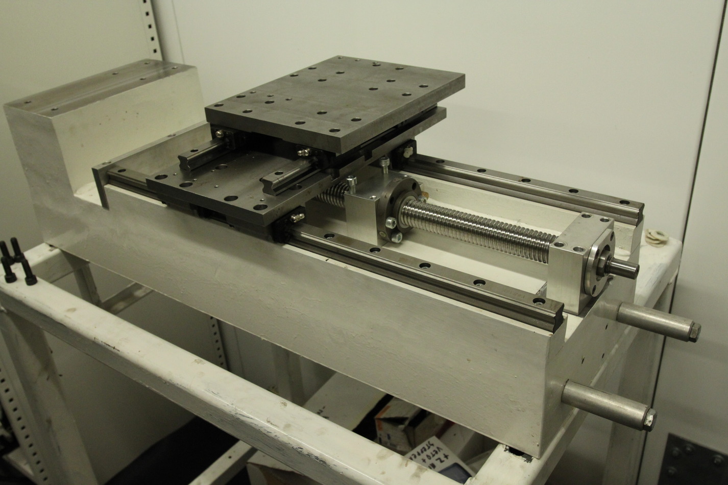
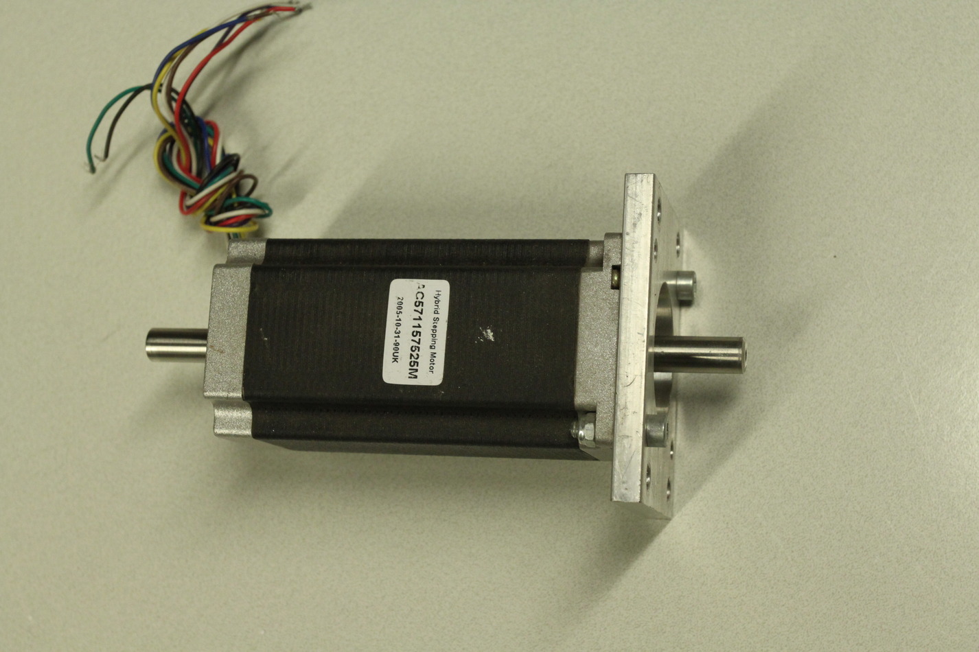
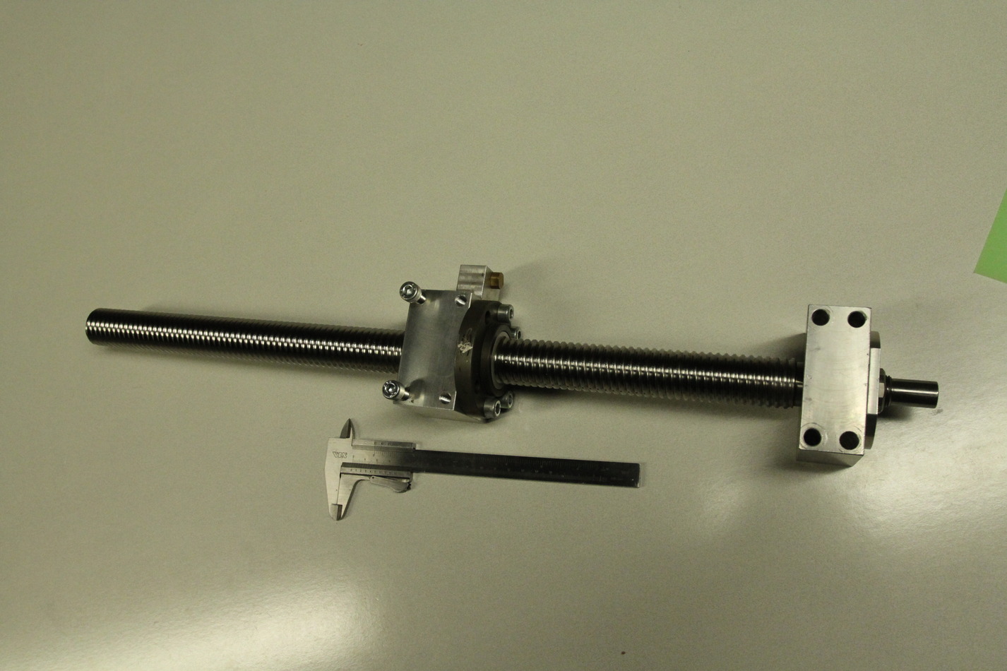
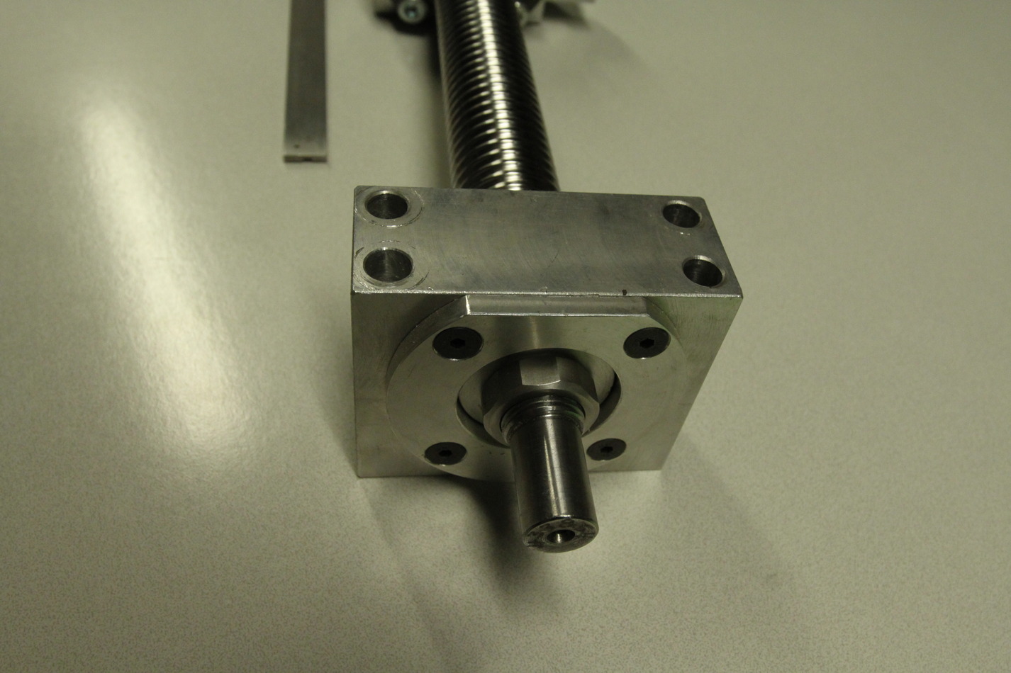
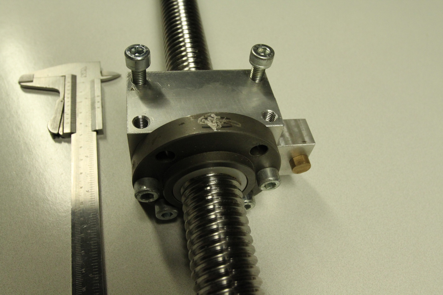
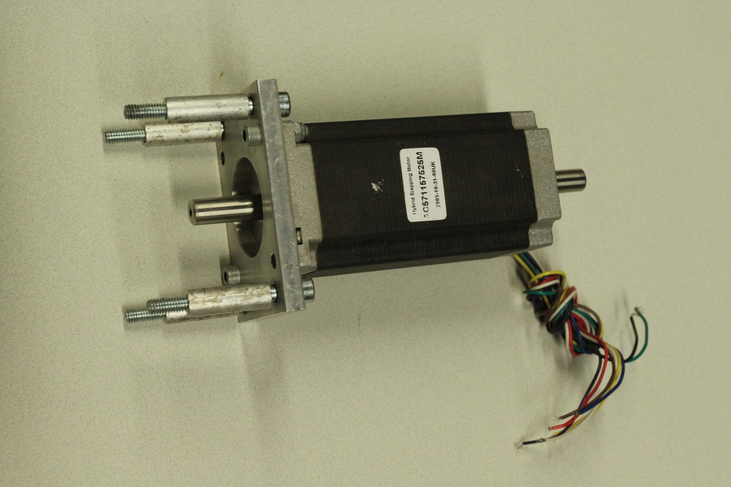
Stepper motors are NEMA23 size with 10 mm diameter shafts (ca 20 mm long). I will most probably not use stepper-motors but NEMA23-size brushless servos instead. The X-ballscrew is 16mm diameter with 4mm lead. It is 158mm long while the nut is 37mm long. That makes for a theoretical max travel of 121mm (enough?). The timing belt pulleys for both Z- and X-axes are type 21T5-36 and 21T5-21 or 21T5-16. That makes for a 1:1.7 or 1:2.25 reduction ratio. The Z-ballscrew is ca 30mm diameter with a 5mm lead (might be 0.2" also). It is 545mm long, the nut is 63mm long, theoretical travel 482mm.

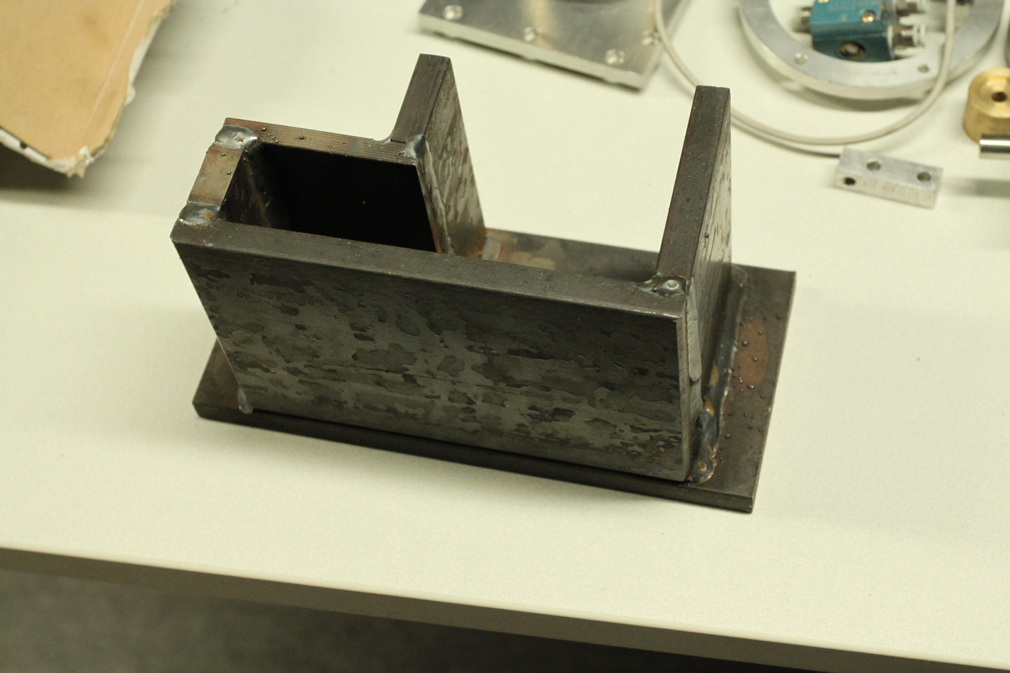
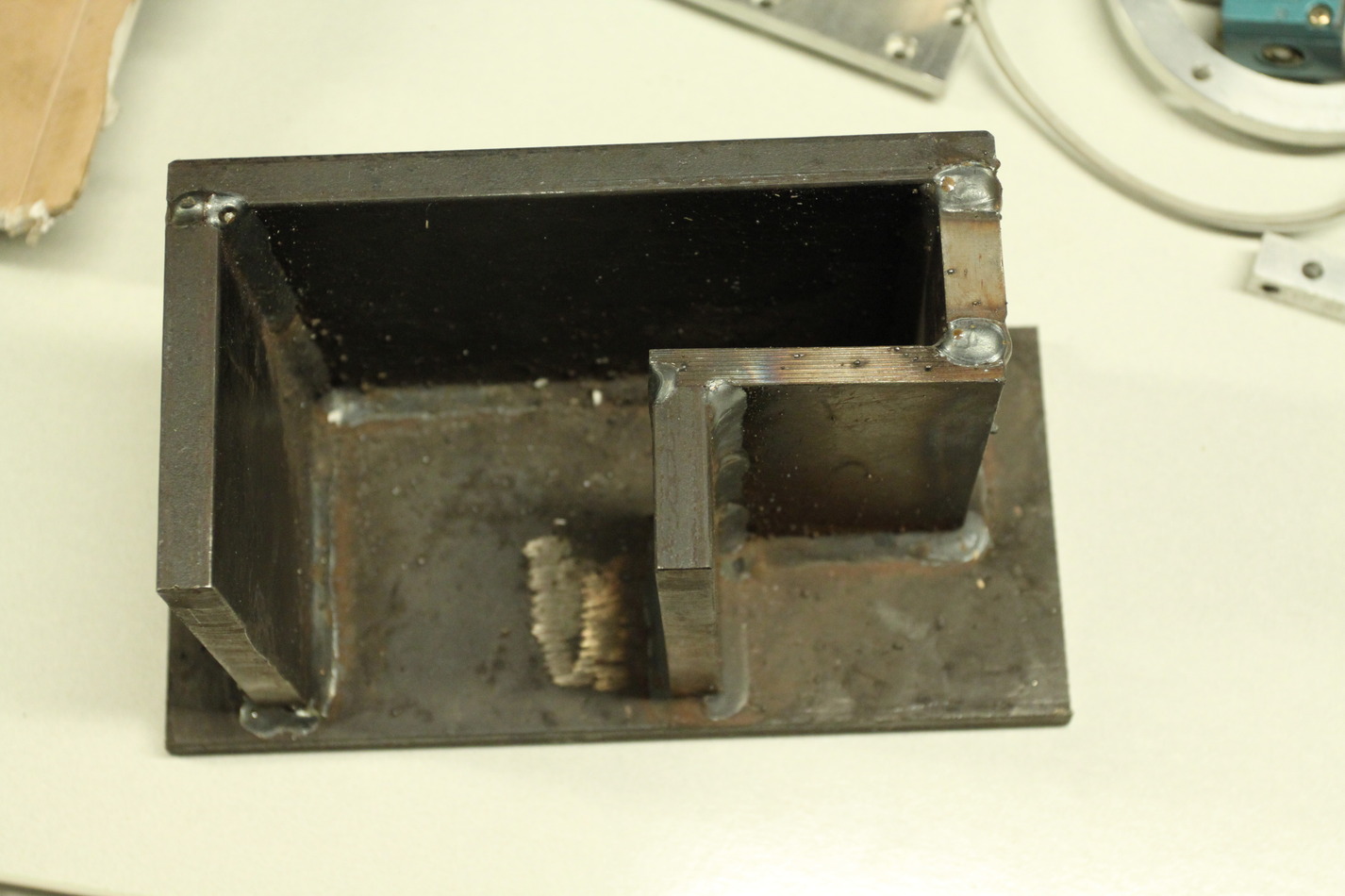
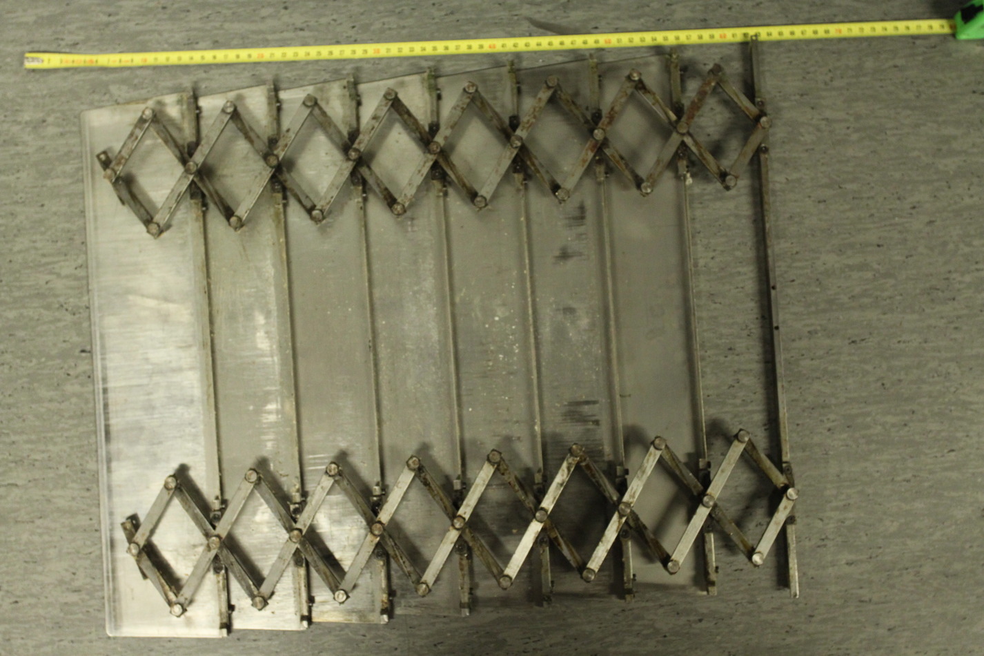
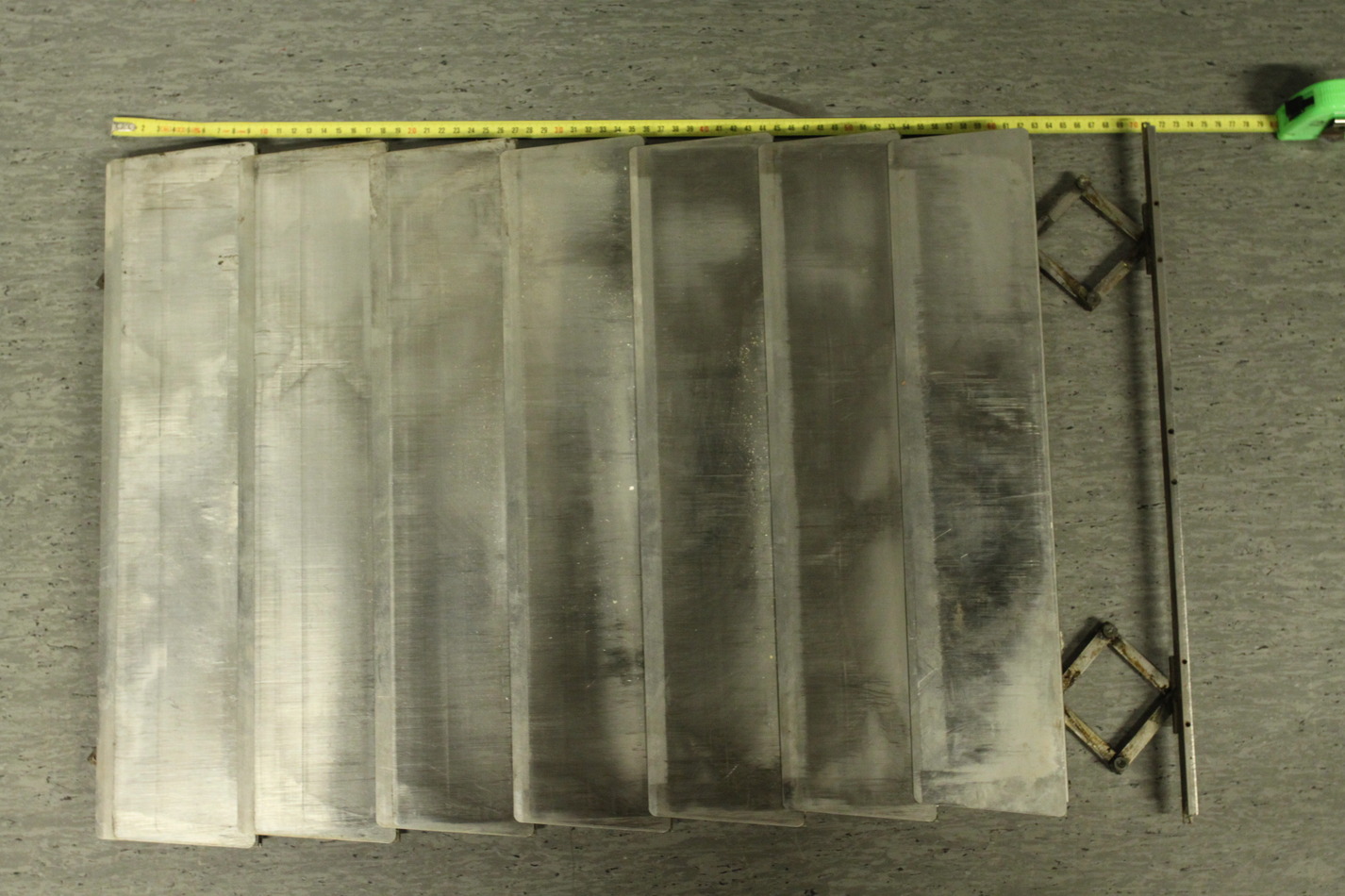
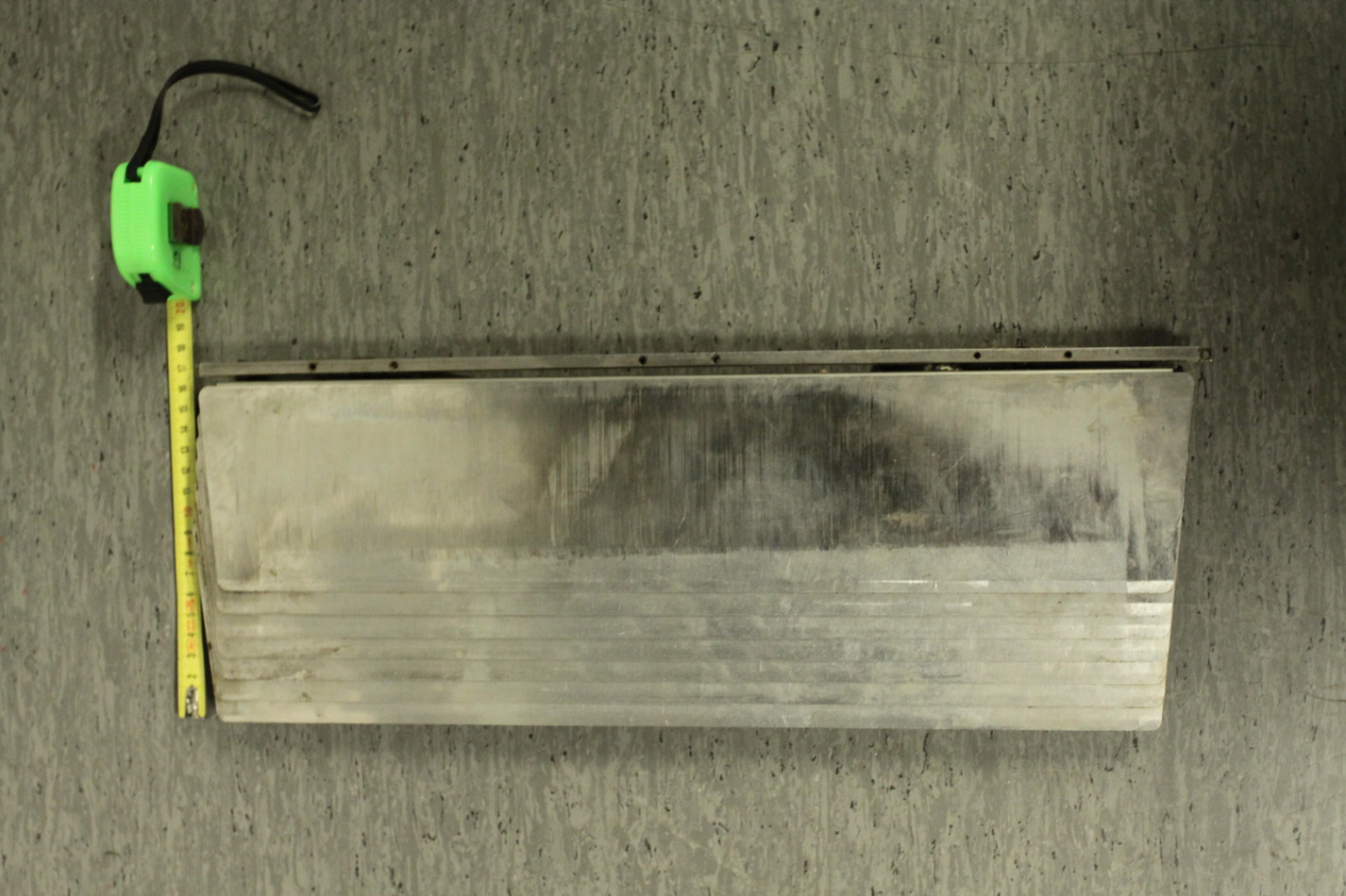
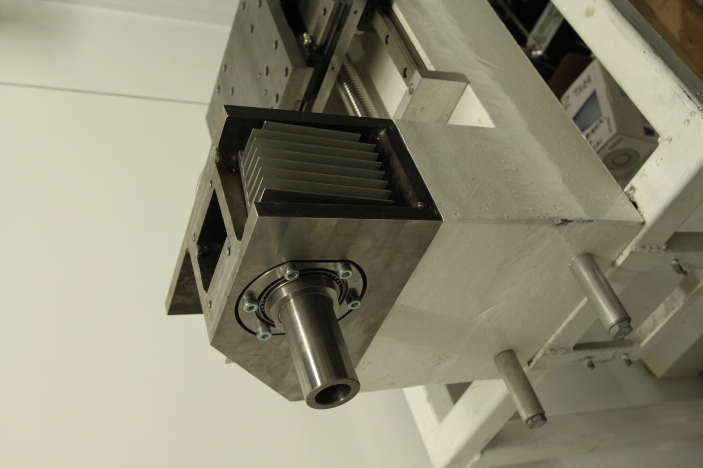
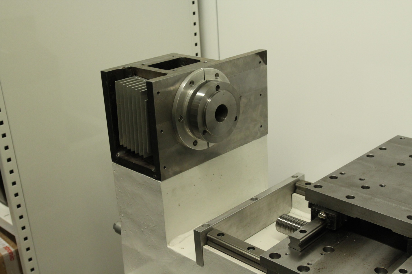
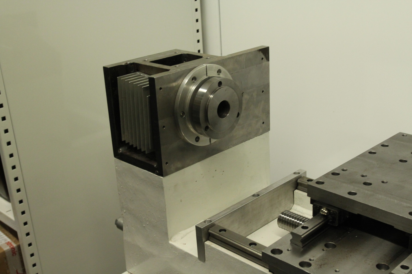
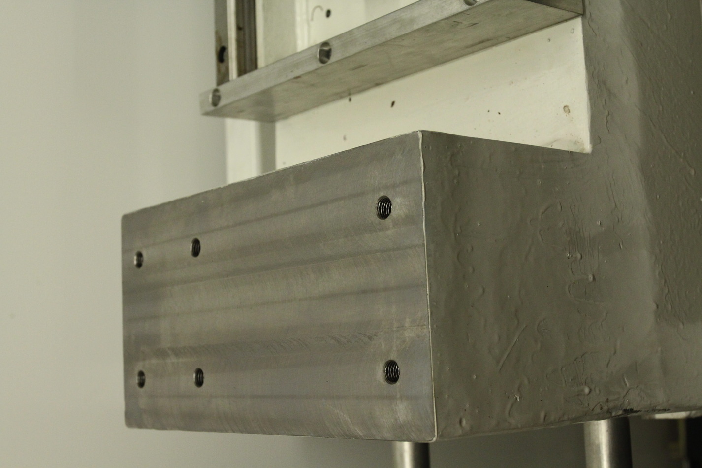
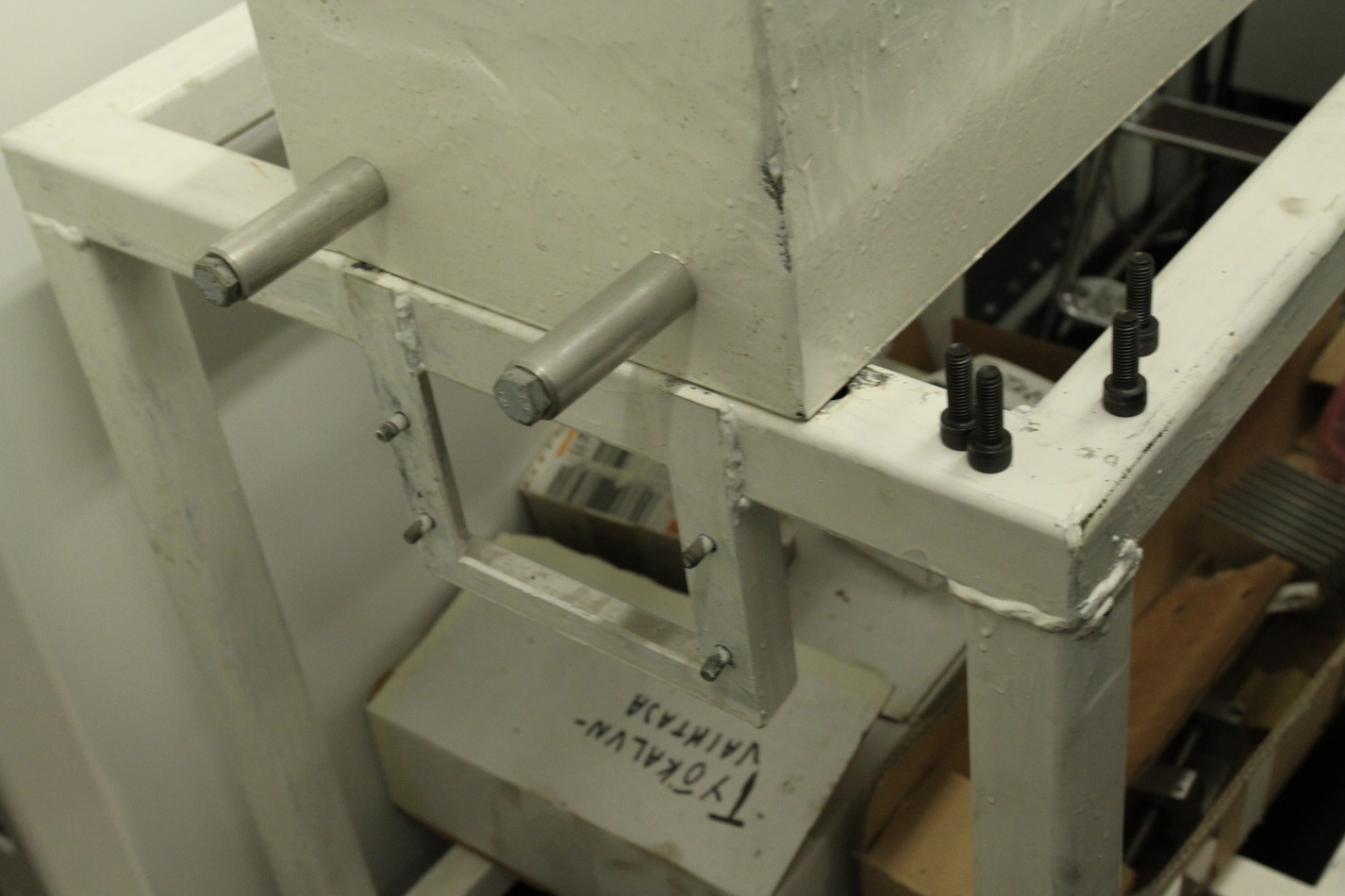
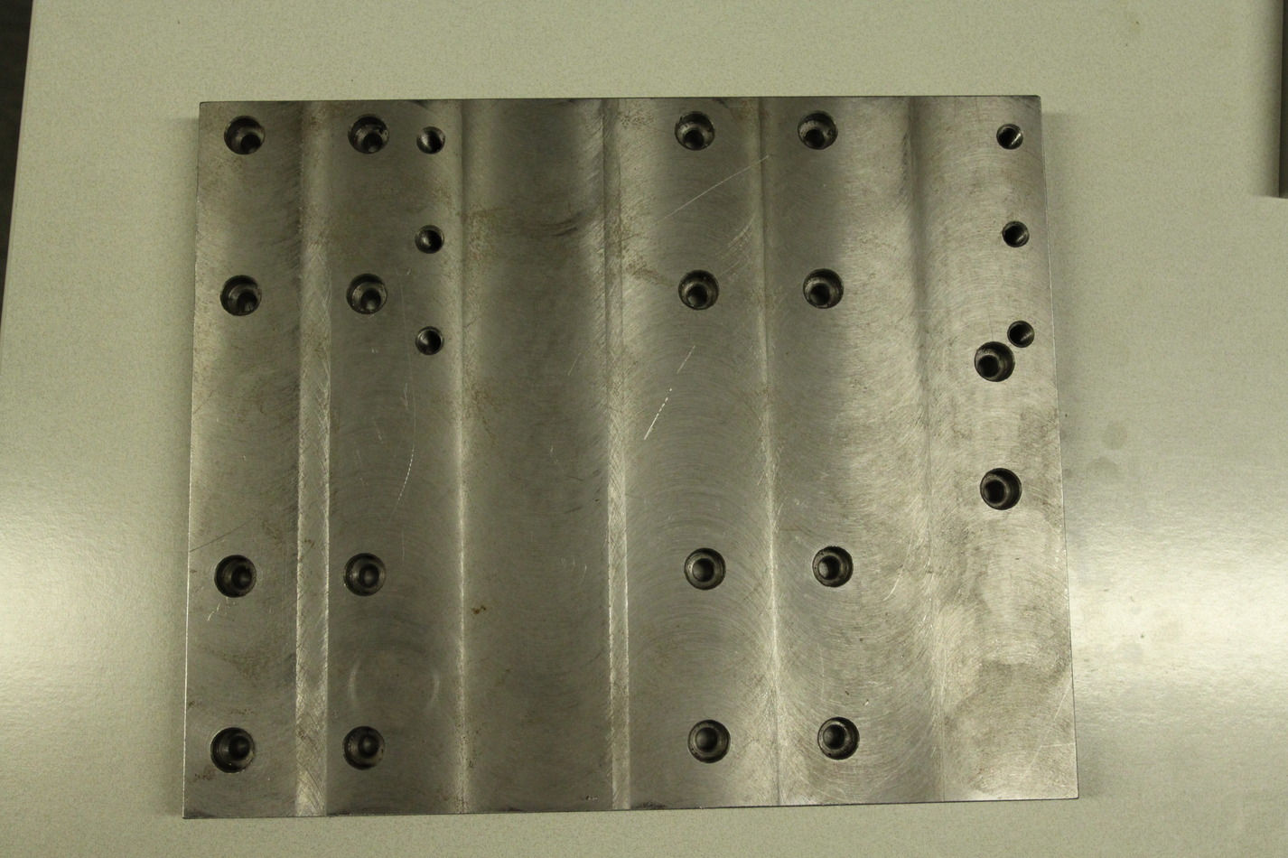
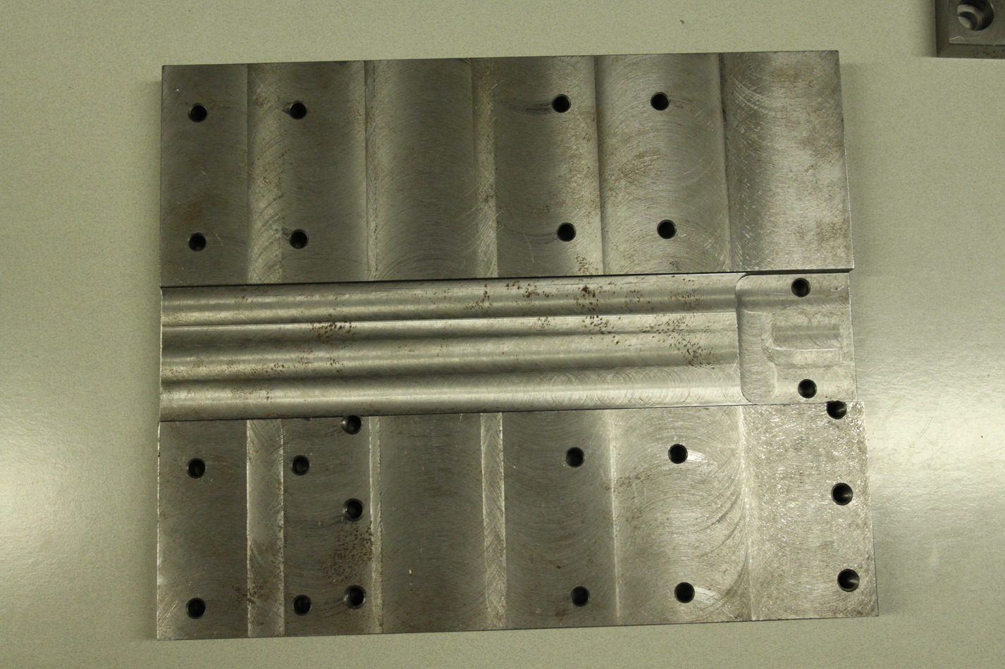
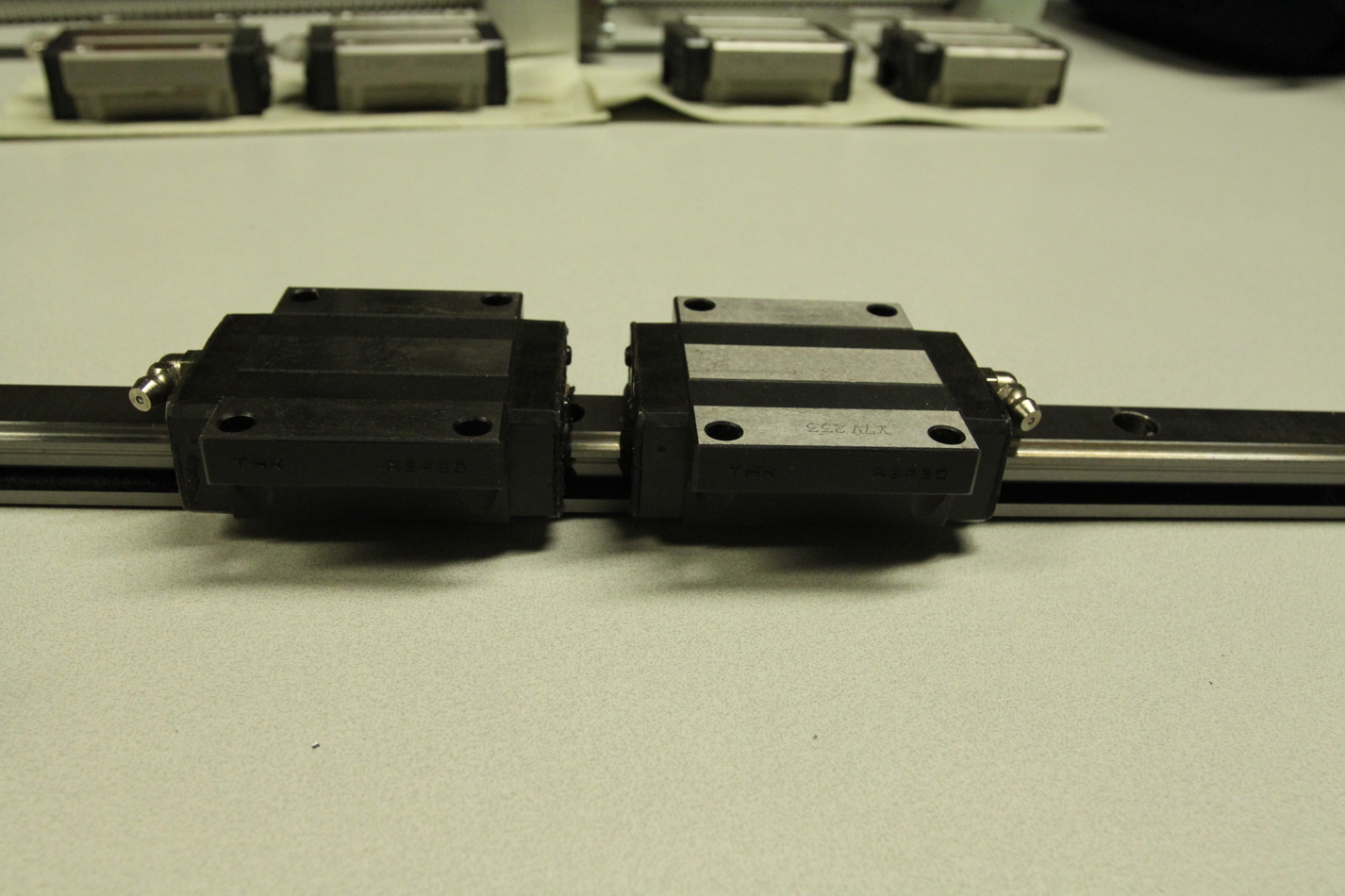
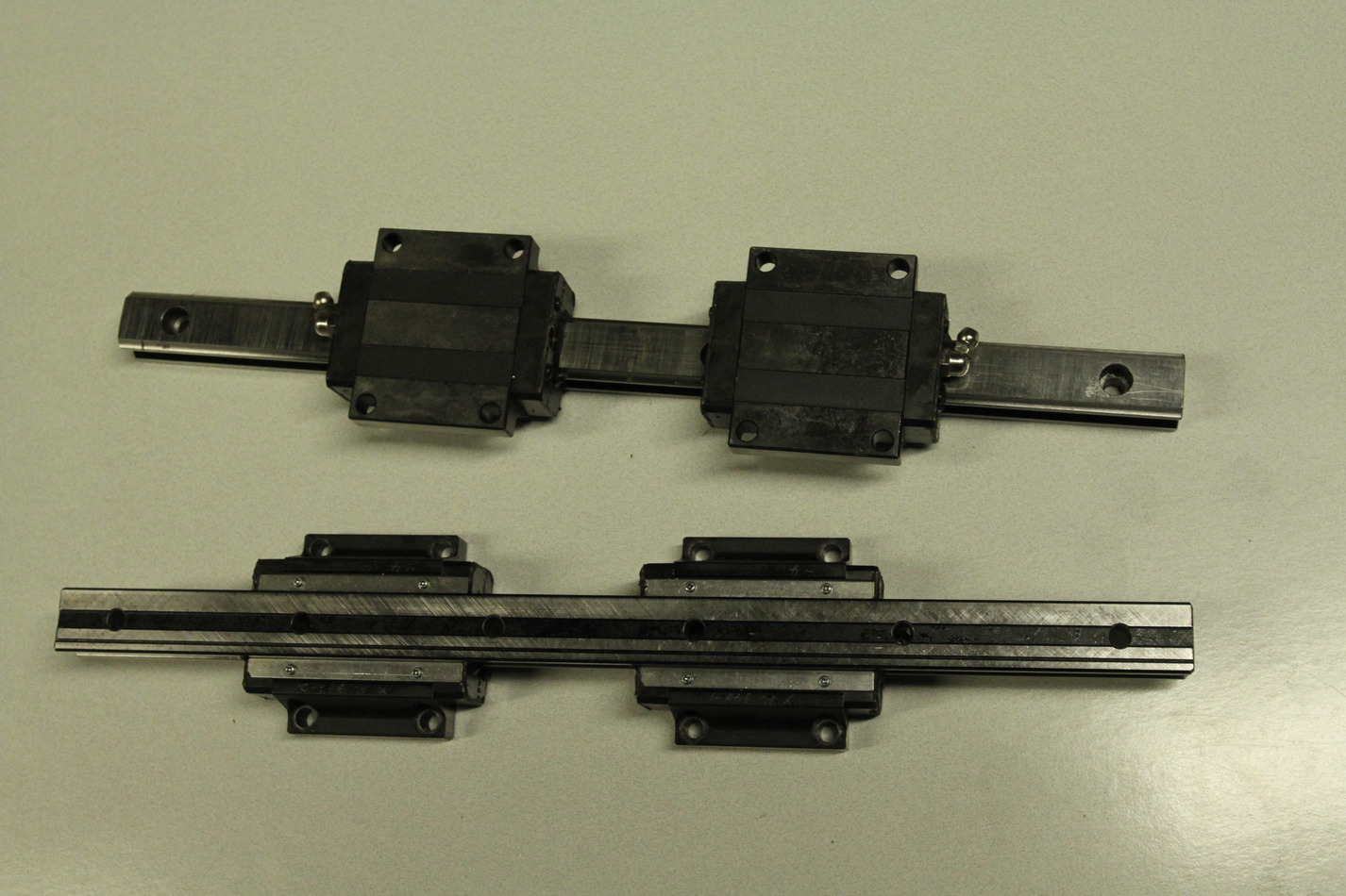
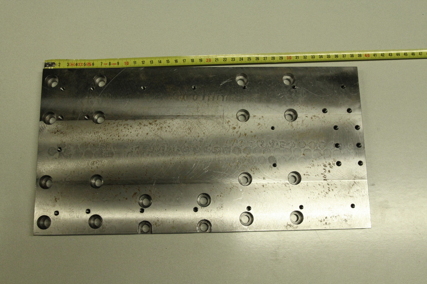
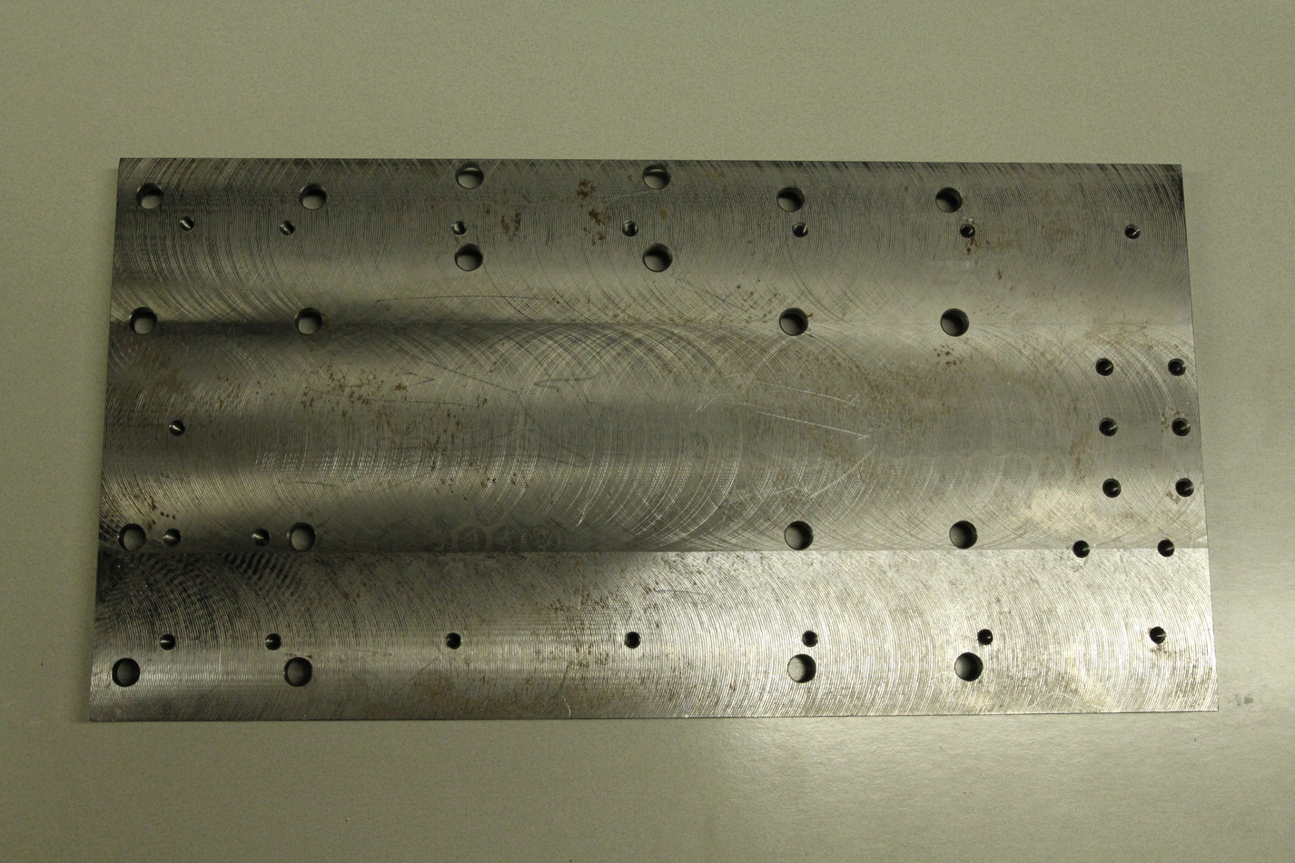
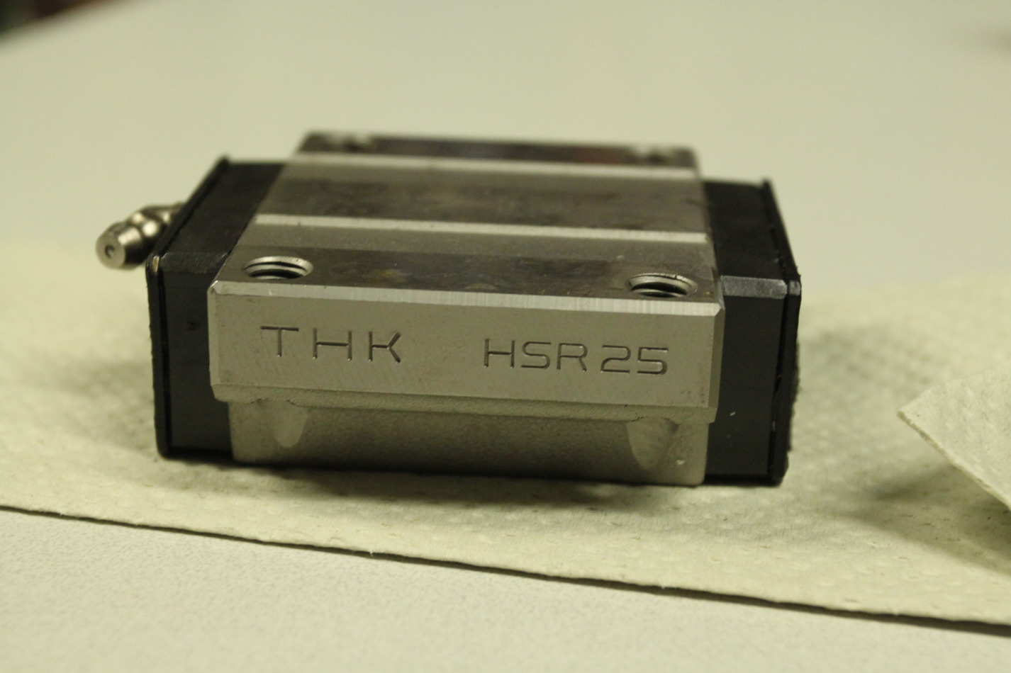
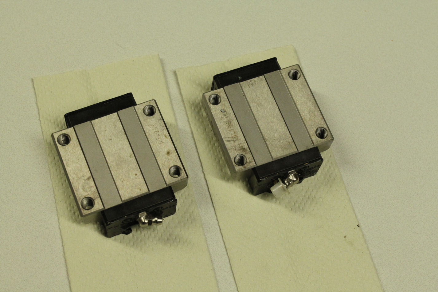
The chip-guard is ca 450-460mm wide and around 185mm long when fully compressed. It extends to much longer than required. The Z-rails are HSR25 type and the X-rails are HSR20 type (length 340mm). The Z-saddle-plate is 380x195x15.3mm. The X-saddle-plate is 275x227x20.4mm.

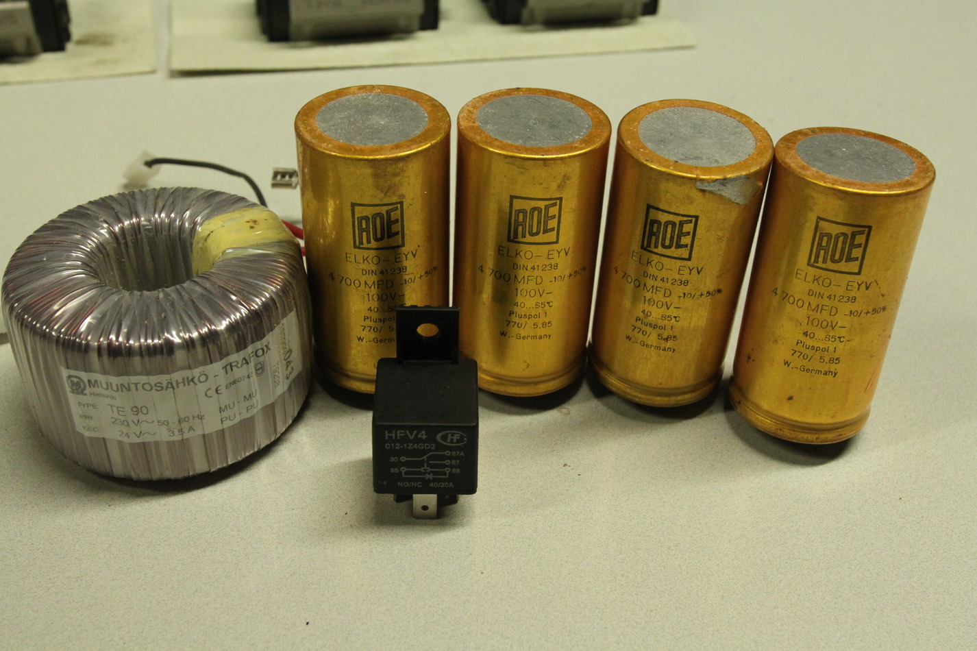
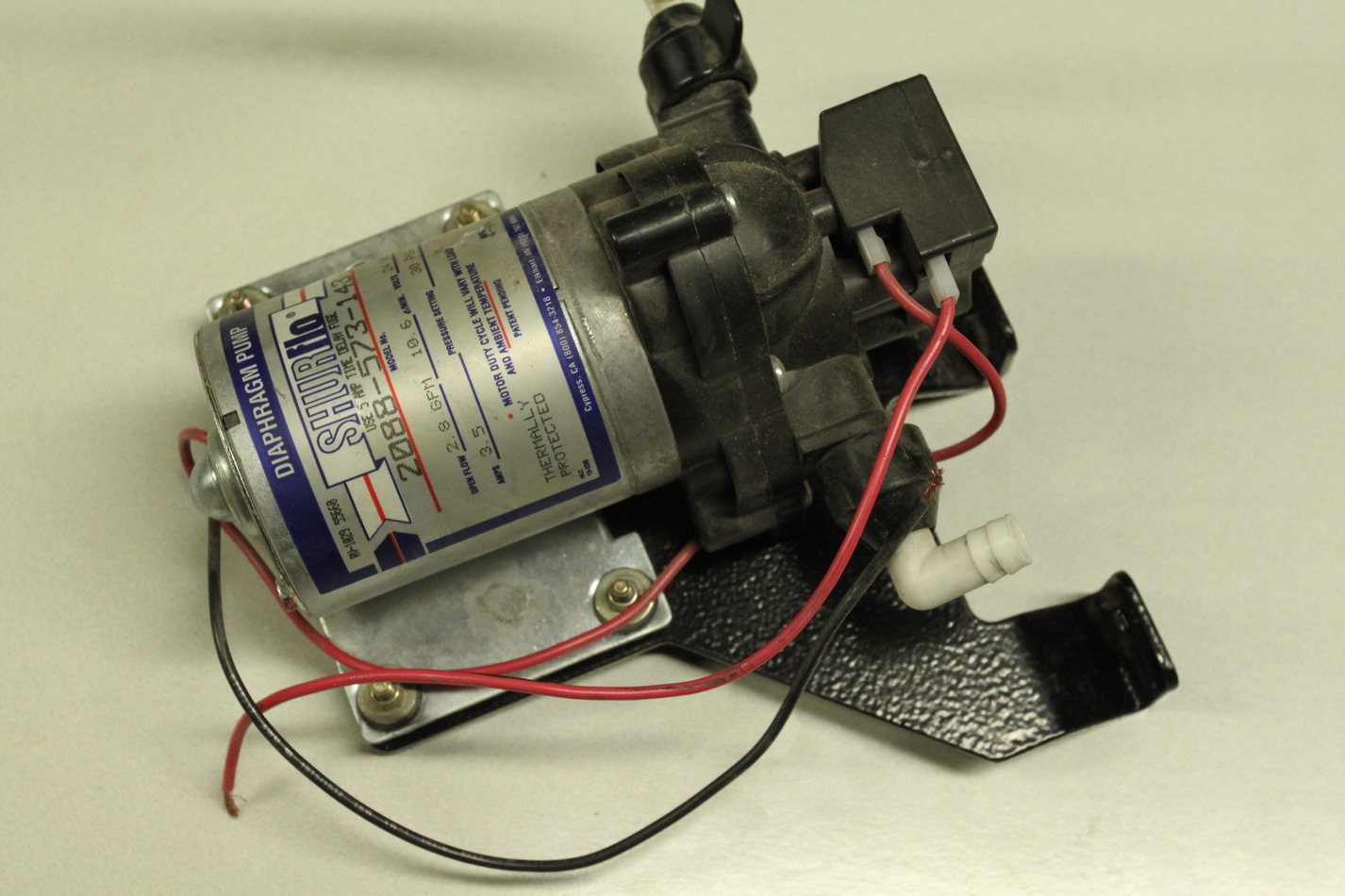
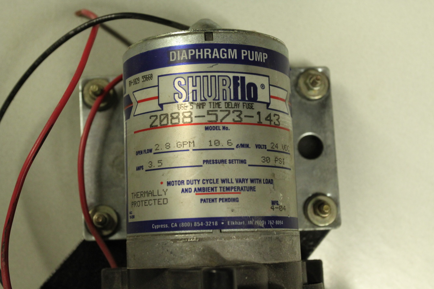
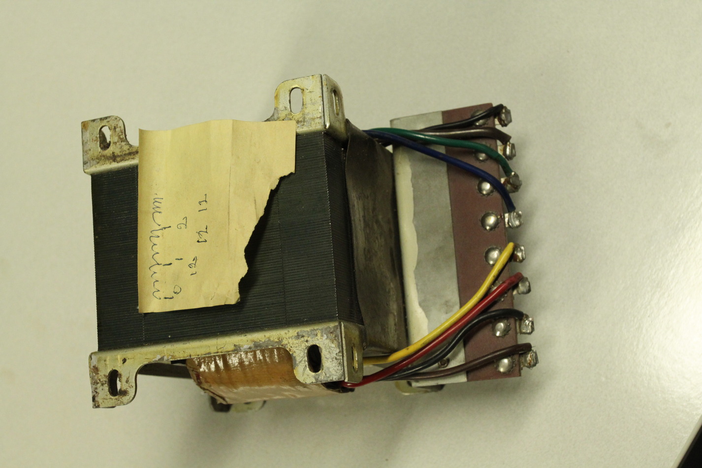
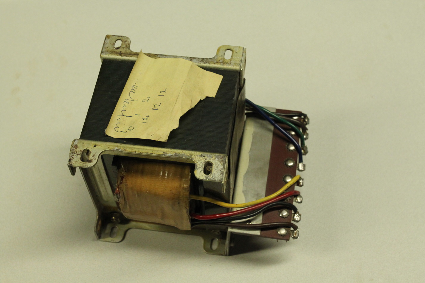
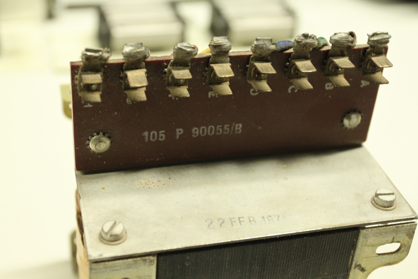
The coolant pump is rated as 24V/3.5A. There is a transformer with a 24V/3.5A secondary for powering the coolant pump.

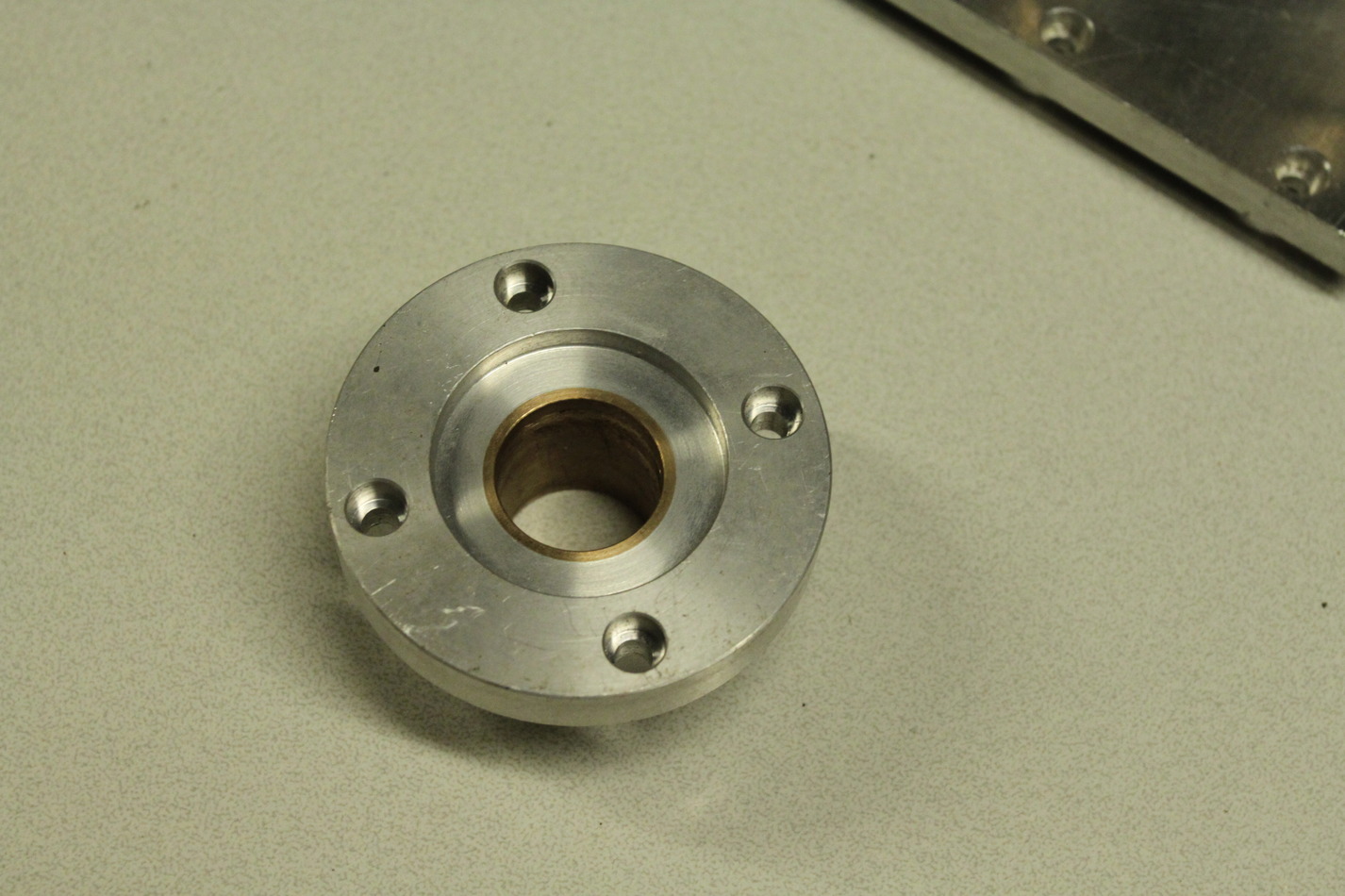
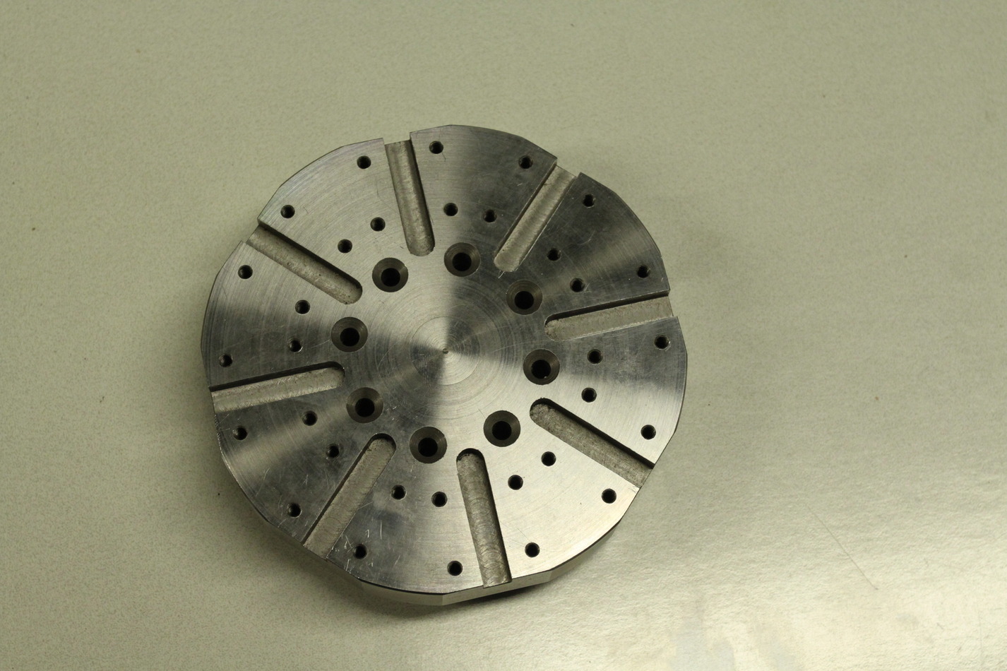
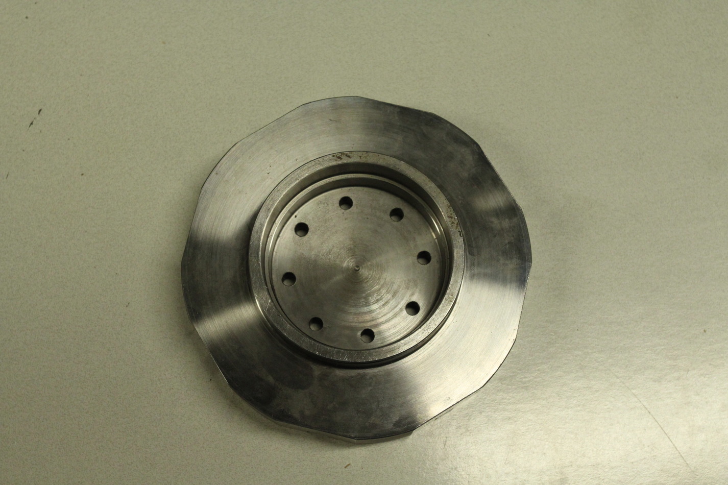
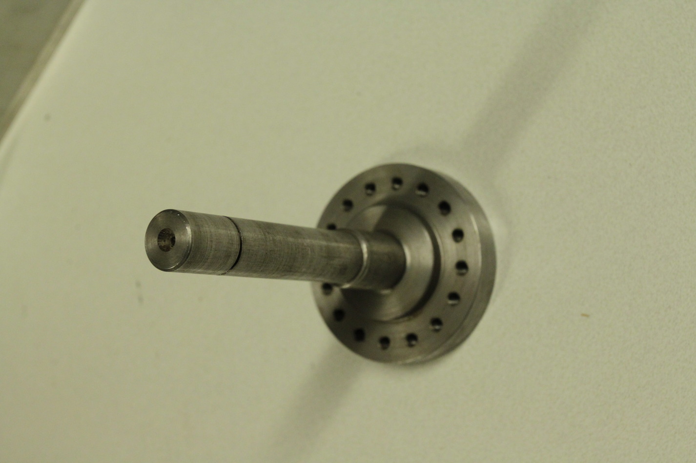
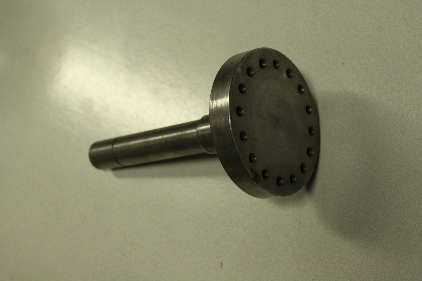
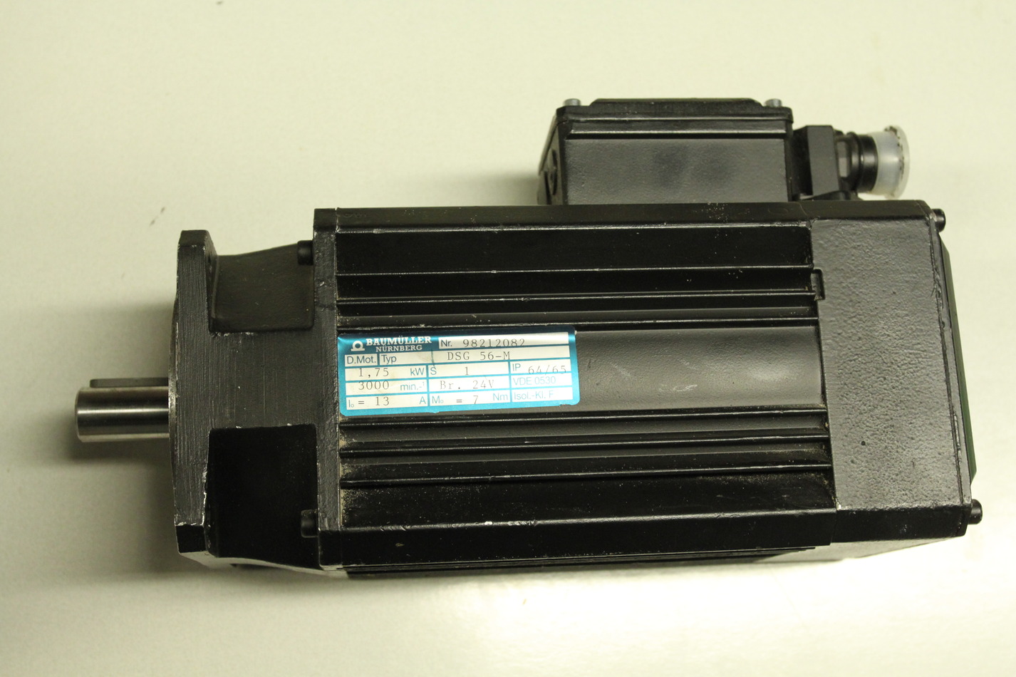
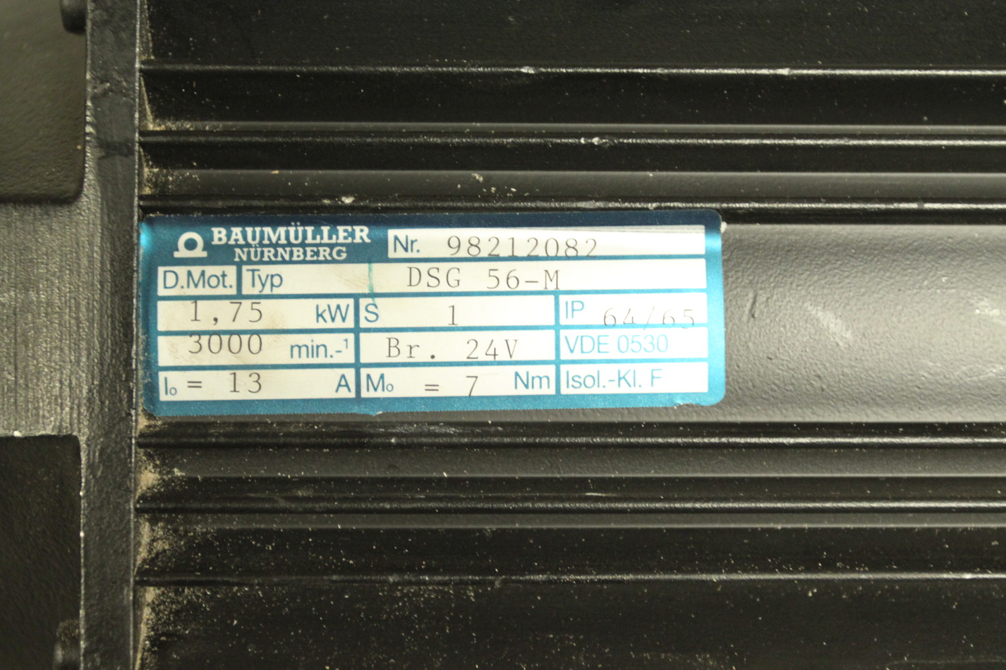
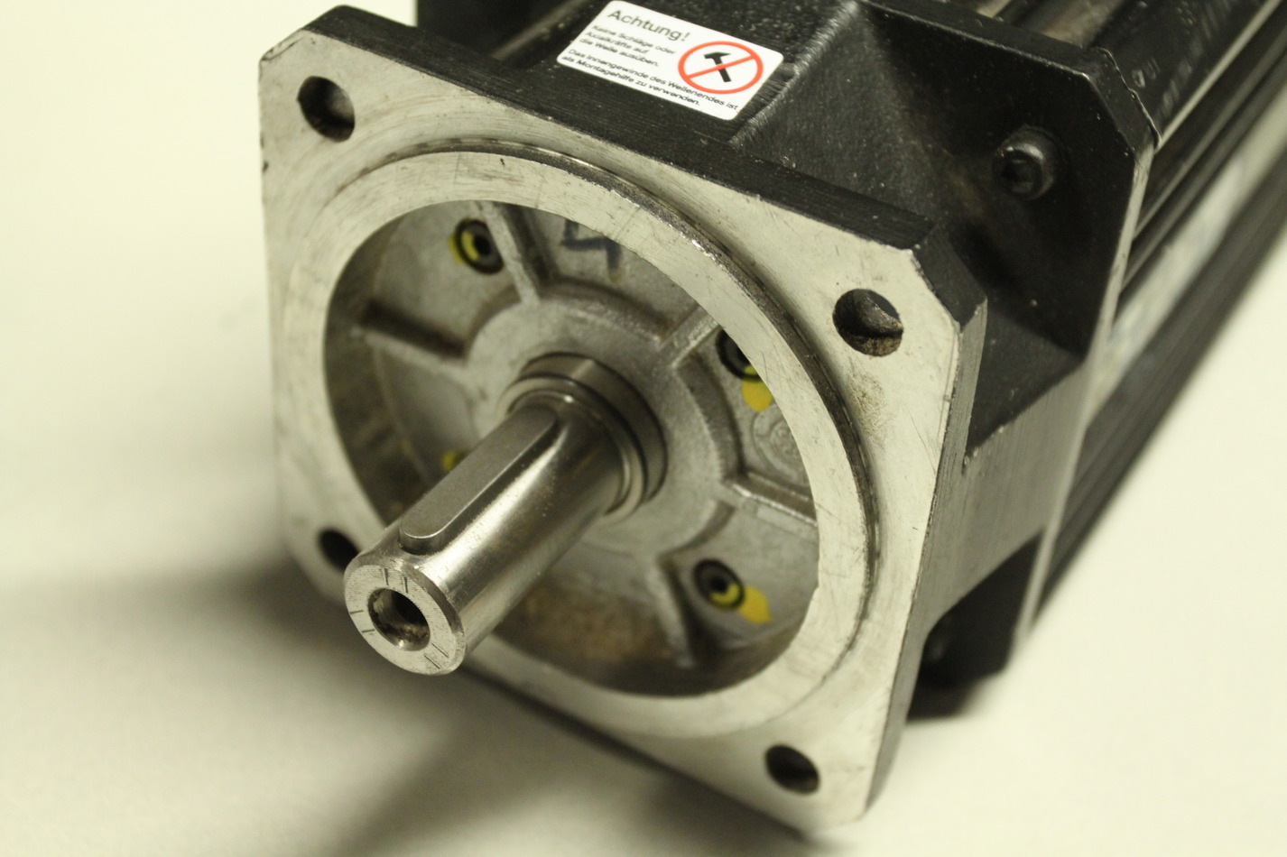
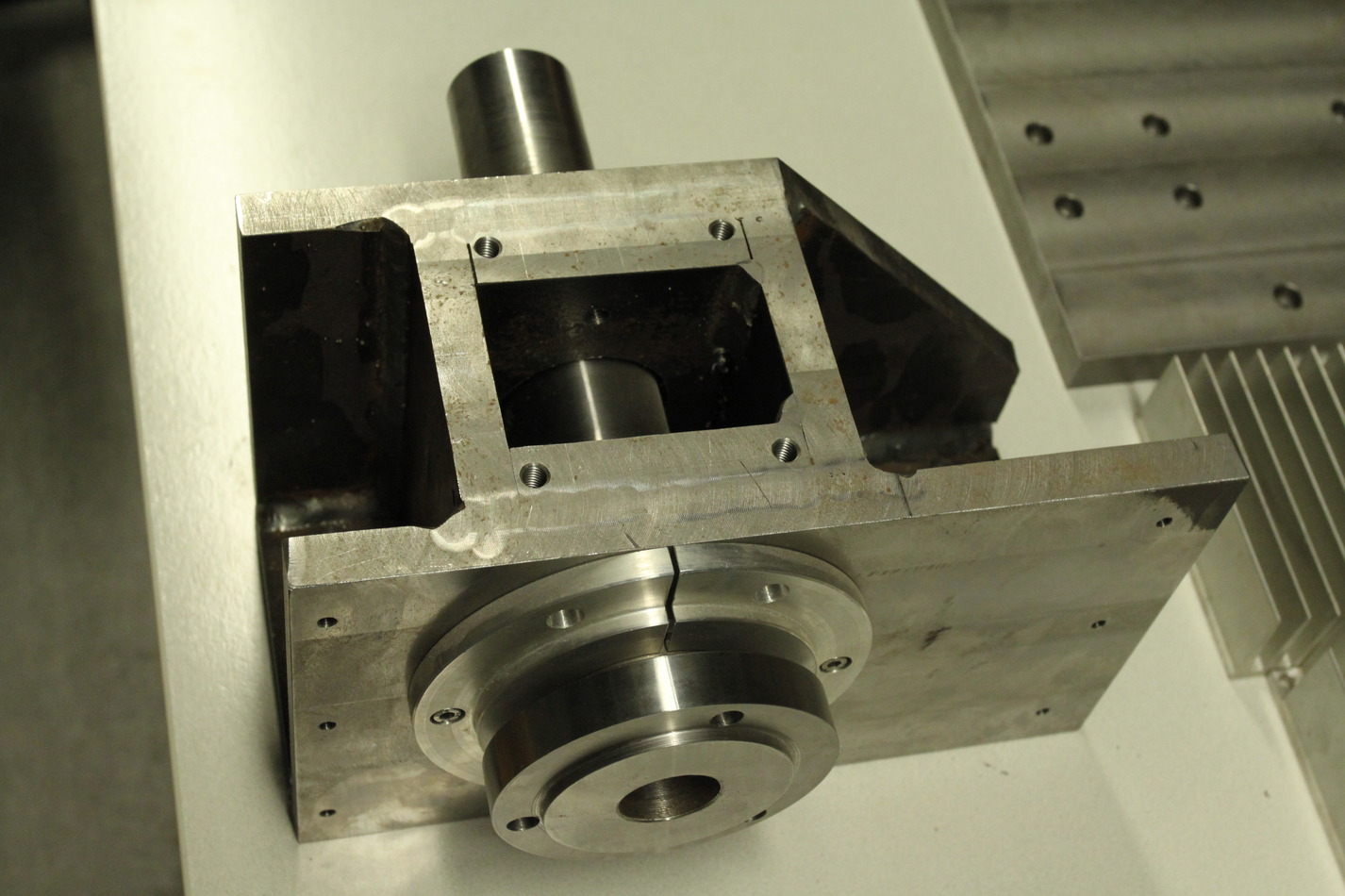
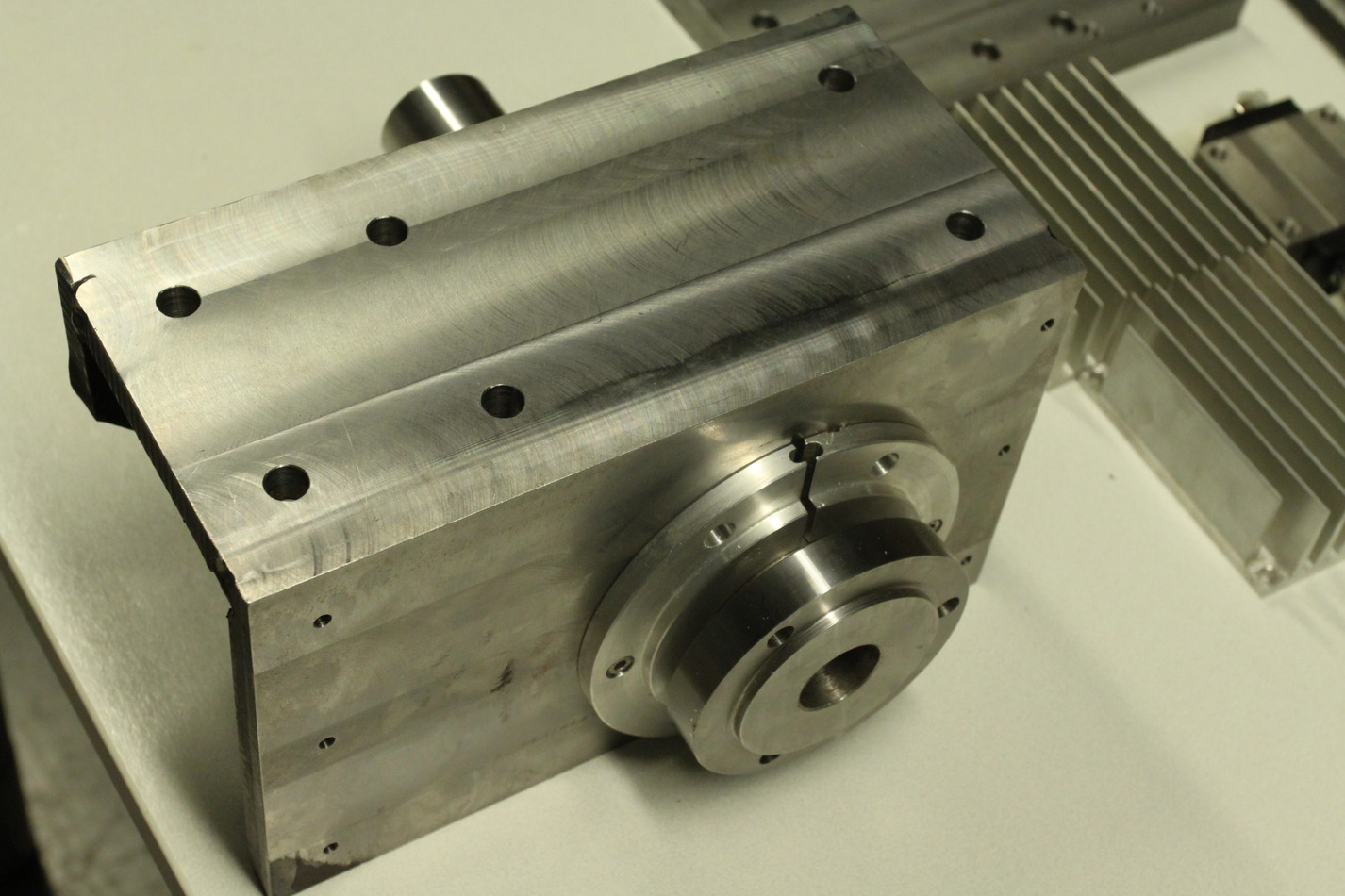
The spindle servo is rated at 1.75kW, 3000rpm, 13A, and 7Nm. The spindle servo axis is 19mm in diameter and ca 35mm long. The spindle itself is 45mm in outer diameter where the pulley for the belt-drive should attach. The chuck-holder is 100mm in diameter.

These images are also on picasa: http://picasaweb.google.fi/anders.e.e.wallin/JHQLathe2009_11_21#