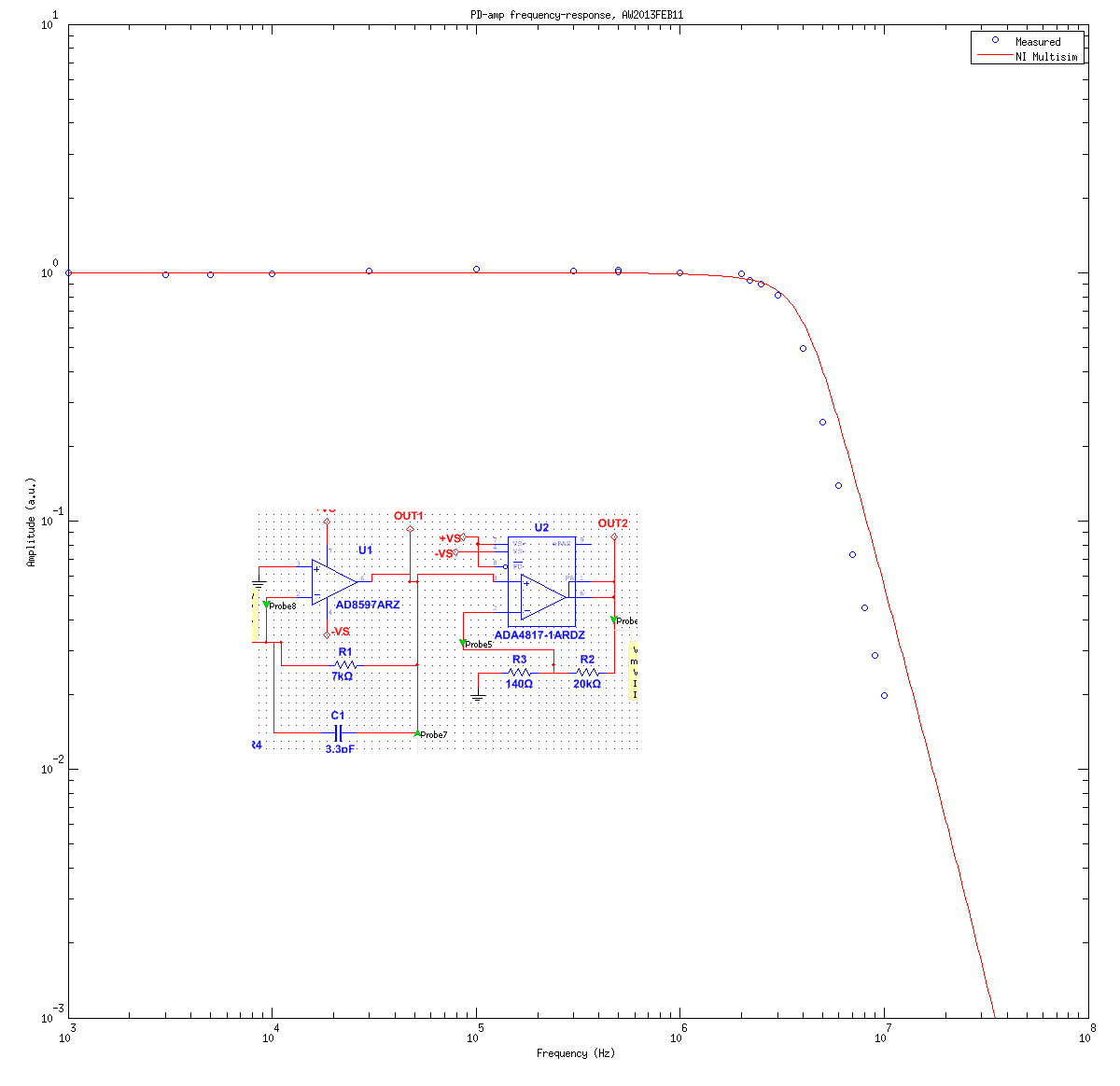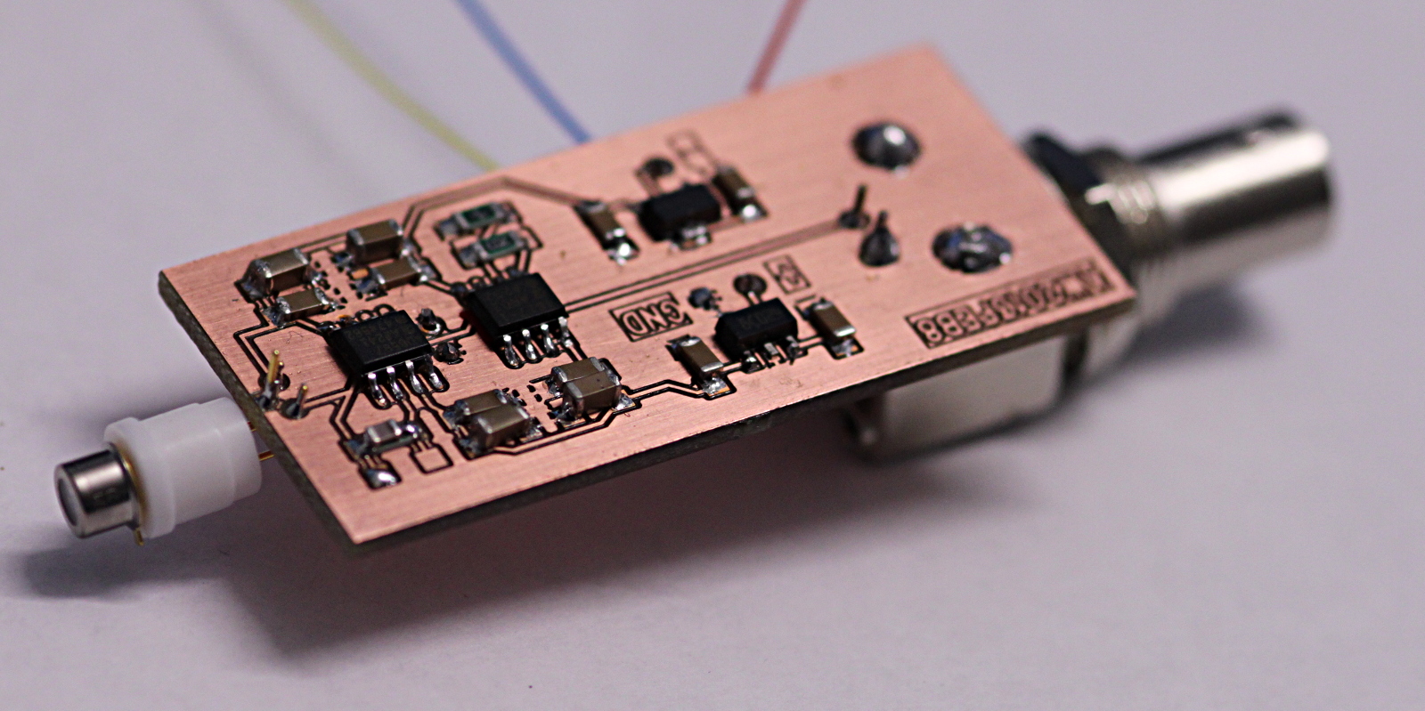
I assembled and tested the latest photodiode-amp today. I tested the frequency response using a red LED driven directly by an Agilent function-generator with an offset of 1.2 V and a 600 mVpp sine-wave. The LED datasheet doesn't specify a rise-time or bandwidth, but I'm hoping it is fast enough to test this 2-3 MHz receiver. I do have some small VCSELs that should be very fast and suitable for testing photodiode receivers up to 500 MHz and beyond.
The signal from the LED caused a 3 V output swing, which explains the slightly lower observed (large-signal) bandwidth compared to the simulated (small-signal) bandwidth. Some of the difference between the simulated frequency-response and the measured one is probably explained by stray capacitance which slightly lowers the bandwidth.