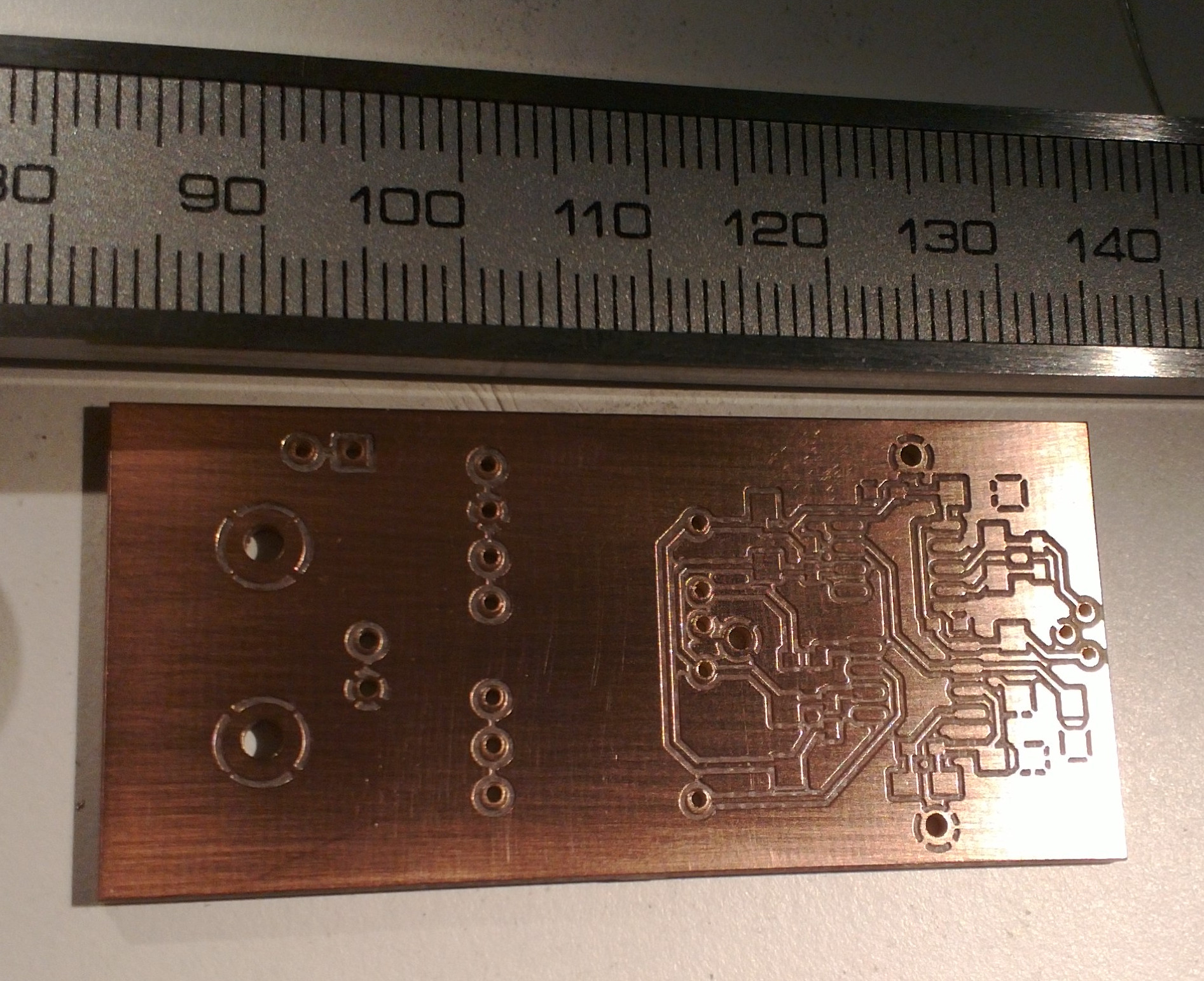
I made this PCB for a second photodiode amplifier today. This one is designed for higher light-levels and higher bandwidth. I will post the schematics along with measurement data when I've tested the circuit.
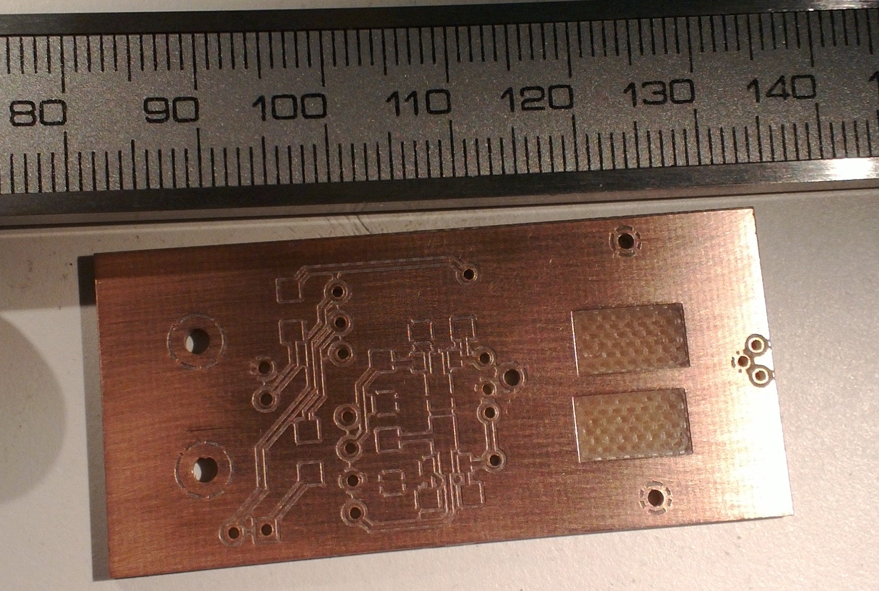
The V-cutter is designed to cut a slot that is nominally 8 mils (0.2 mm) wide, but the actual cut-width depends on how the z-axis is adjusted. Removing the ground-plane copper from under the high-speed op-amps is supposed to minimize stray capacitance.
I would have removed more of the copper to further reduce capacitance. Just removing the copper from under the chip ignores the traces and the fringing between them.
OK, but what about RF-shielding? If you remove a lot of copper around the amp, would you put a separate RF-shield some way away from the underside of the PCB?
Or is it OK to just house the PCB in an aluminium box?
You built the whole thing inside of a metal tube. Why not just ground the tube? It is the capacitance formula that makes distance king here.
The thing is you picked a photodiode with very low input bias current which is good but with this layout I doubt you will really make the best use of it. In fact depending on the dark current of your diode is might not even matter. How large is you feedback resistor and what is your target bandwidth?
I haven't finalized the design for this yet.
I'll build two of these, one for about 2MHz bandwidth, and the other for 300 MHz.
For the 300MHz (a beat-frequency measurement between two lasers) there will be 500 uW or more optical power available, so making the amplifier shot-noise-limited should be possible.
At 2 MHz (for PDH-locking one of the lasers to a cavity) there will be only 5-10 uW of light available, so it is harder to make it shot-noise-limited.
I have been looking at the ADA4817 op-amp for the transimpedance stage, and maybe an AD8000 voltage-amplifier after that.
For photodiodes I have Hamamatsu S5971, S5972, or S5973.
I have been reading Hobbs's book (Electro optical systems) and plotting the noise power-spectral-densities, maybe I will blog about this later. For a 2MHz bandwidth it may be overkill and bad for the amplifier voltage-noise to use a wide-bandwidth op-amp such as the ADA4817 with a GBWP of 410 MHz and a slower op-amp would be better.
Damn. Those are nice diodes. You are going to have to make to totally different designs for each device I think.
You will have a hell of a time trying to use a 410MHz GBWP opamp at 2MHz. Not just for noise reasons. The layout rules are totally different. The 410MHz part to avoid self oscillation and other nightmares with things like power decoupling requires you to follow the manufacture recommended layout. Typically I pull up the evaluation board layout and compare it to the guidelines in the data sheet to see how they expect things to be implemented.
Around 2MHz you can probably get by with out the reverse bias voltage on the diode. The 300MHz you almost certainly have to use it. That will drive your noise floor up more too. Avoiding reverse bias is nice because it also reduces stray currents on the input side of the transimpedance stage. The guard ring around the diode and opamp inputs is continuous.
I see from the photos that you are working on FR4. If you really need to go down in current you will have to change board material or not use a board at all. Down at really small currents we tend to build everything using old (1940's style) methods on teflon posts. FR4 just has too much stray current. This is why the diode socket is or at least should be made from Teflon.
http://portal.national.com/rap/Story/0,1562,4,00.html
http://portal.national.com/rap/Story/0,1562,5,00.html
I am not familiar with Hobb's but I have built a lot of voltage to current and current to voltage things.
Posted just because I really geek out on femtoamps
http://www.ti.com/general/docs/video/Gallery.tsp?bkg=dark&entryid=0_uv5g0wh6&lang=en
I really liked national semi before TI. They used to let you just download the video. I hate flash.