I mounted a servo on the x-axis of the mill today and did some PID tuning. The video shows a ca 300mm rapid move at 5500mm/min (217 IPM). Below some hal-scope views of what's going on in the PID loop during the move.
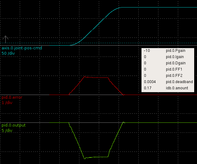
Here only P-gain is used and the machine needs to lag behind the commanded position (blue) a bit (slightly less than 1 mm, red trace) for the DAC output (green) to reach to reach the required level.
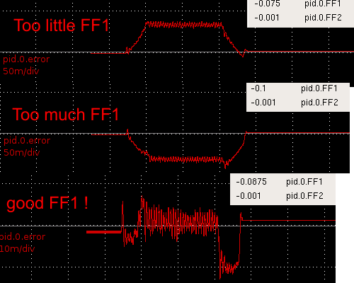
The lagging behind is curable with FF1, 1st order feed-forward. FF1 adds to the DAC output in proportion to the commanded velocity. With too little FF1 (top, note scale for red trace is 20x finer than in the first pic) the machine still lags behind. Wit too much FF1 (middle) the machine leads commanded position, and I figure the bottom trace has about the right amount of FF1 since the error is small and symmetrical around zero during the 'cruise'-phase (constant velocity) of the move.
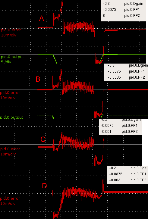
I found FF2 much more tricky. Note again the scale is finer than before (100x finer compared to the first pic!). FF2 is 2nd order feed-forward and adds DAC output in proportion to the acceleration of the commanded position. In A there is no FF2 and the machine lags during acceleration and leads during deceleration. In B I've added FF2 and the error during acceleration seems to be a bit better. C has more FF2 and both the acceleration- and deceleration-phase errors are better. Then in D it seems I've overdone FF2 since the acceleration-phase error gets much worse (machine is leading commanded position), while the deceleration error improves.
I'm confused. What could be asymmetric so that FF2 acts differently during acceleration and deceleration? I should add that I am using an m5i20 to generate PWM for pico-systems servodrives (basically a H-bridge). There is no motor current, motor voltage, or velocity feedback, only feedback from a 4000 pulse encoder. The ballscrews are 2.5 mm/rev so one count is 0.000625 mm. The peak error during acc./dec. in the FF2 figure above is around 0.01 mm or 16 encoder counts. During cruise-phase the error is smaller, maybe only +/- 8 counts.
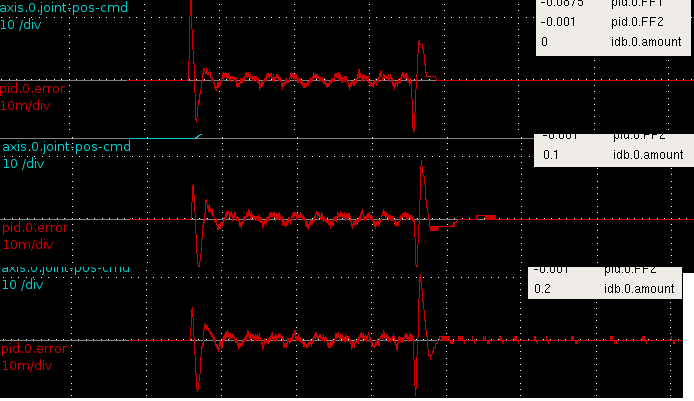
I then tested the inverse-deadband component which is supposed to linearise the DAC-motor system. I'm not sure what these results mean yet. The first error-peak is lowered, but there's an opposite effect during deceleration. This is a slower move and shows some periodic error during the cruise-phase, I wonder what that could be?
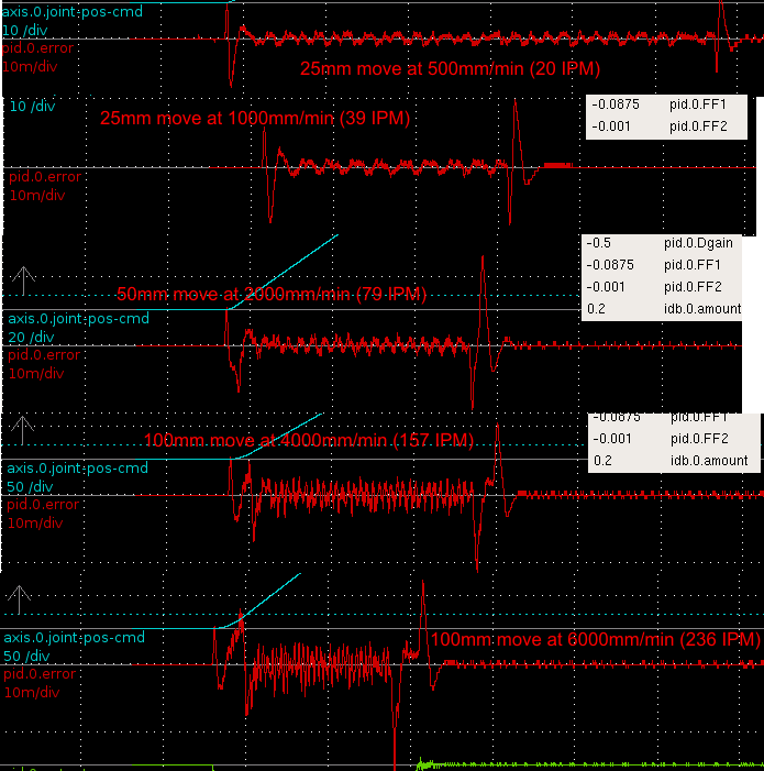
Finally some traces recorded with different length moves and different feed-rates. In reality 1000 mm/min is about the highest feed-rate used while machining, and everything higher than that is mostly for show only 🙂
Clearly higher feed-rates are more difficult for the PID loop. The acceleration/deceleration phases are still difficult, and there remains an asymmetry where with the current PID-parameters the acceleration phase works a bit better than the deceleration phase. I think with another choice of FF2 that could be reversed so that deceleration is fine but there is more error during acceleration.
I wonder if there is something peculiar to only torque-mode servo PID-loops that I should take into account? Something to do with the asymmetry between acceleration/deceleration...
The inverse deadband does it wrong. Dead band does not occur at DAC zero but at motor current zero crossing. So you would need at least current direction sensor to make it work properly.
Maybe this is the reason for asymmetry.
Moro!
Oletkos löytänyt vastauksen tohon FF2:n erillaiseen käyttääntymiseen kiihdytys ja hidastusrampissa?Itse painiskelin saman asian kanssa eilen. Mieleen tulee mekaaniset joustot, hihna, mekaaniset kuularuuvin välykset, "slip stick" ilmiö. Eli kuvittelee tilanteen jossa kaltevaa pintaa pitkin lasketaan takkaa köyden varassa. Takka ei lähde liikkeelle muutakuin pikkaisen tönäisemällä ja kun lähtee niin kiristää köyden kunnes taas pysähtyy. Eli eräänlainen kitkasta ja välyksistä johtuva värähtelyilmiö??
Terve, näistä testeistä on jo muutama vuosi, ja tämä servoilla rakennettu Otpi BF20 on kyllä toiminut hyvin niillä syöttönopeuksilla mitä käytetään koneistuksesta.
Teron kommentti saattaa olla myös oikeilla jäljillä, eli tällainen servo josa mitataan vain enkooderilla ja ohjataan PWM:llä jännitettä ei ole täysin ideaalinen. Paremmissa servovahvistimissa mitataan myös vaiheiden virtoja/jännitteitä ja päästään ehkä tuunaamaan paremmin vastetta.
Harrastelijabudjettiin sopivia servo-ajureita on nyt 2015 ehkä paremmin saatavilla kuin mitä oli 2008 jolloin valitsimme pico-systemsin PWM-ajurit.