Chris Radek made this very nice demonstration of how EMC2 controls a 5-axis machine!
Month: November 2007
Microfluidics test
I've been playing around with a microfluidic channel, to be used with optical tweezers experiments later. There's clear fluid coming in from the left in the wide (ca 30um) channel, and I've colored the fluid from the top red and the fluid coming in from the bottom blue. The top and bottom channels are narrower, ca 10um.
This page should have 3 videos, but I put them on Jumpuct and they have disappeared - sorry!
Here all the channels are on at first, then the red channel is switched on/off two times.
Here's the same thing, but switching the blue channel on/off.
Here the clear channel is switched off, and the main channel fills with red/blue fluid.
It's interesting to follow the laminar flow at these very small Reynolds numbers - the fluids effectively don't mix at all (they do mix by diffusion, but very slowly) and there's a clear boundary between red and blue. At the end the clear channel is switched on again.I'm using pressurized air to drive the fluid flow, similar to a product from French company Fluigent (nice videos here and here). Their product sells for around the price of a small car, so I'm thinking I can come up with a DIY solution for slightly less. Switching is by solenoid valves that switch either high pressure or ambient pressure to the fluid bottles (2ml Eppendorfs). The pressures required are surprisingly small, here I'm using the smallest pressure my regulator will output, 5 psi, but I have a feeling this is too much... so I'll need a pressure regulator with fine control between 0 and 5 psi, any ideas?The other option is using gravity to drive fluid flow, 0.5m H2O is around 5 kPa or 0.7 psi which could be OK. The problem is you then have to switch the fluid lines directly. I tried this with solenoid pinch-valves, and the valves create huge pressure transients when switching off - completely flushing the channel with rapid flow. So the gravity driven solution requires valves that open and close very gently.
Spektrum DX6 antenna mod.
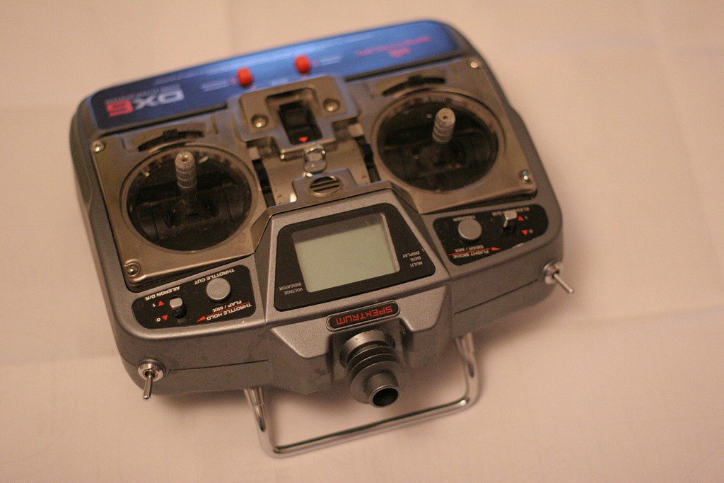
By popular demand, some notes on how I've placed the antenna of my Spektrum DX6 transmitter inside the case. I've been using the radio like this ever since I got it and provided that you hold up the radio more or less vertically and not hide behind large metal constructions or things like that the range is fine. The benefit of the internal antenna is that I don't have to worry about breaking it while sailing it or storing the protruding thing in the toolbox. When it rains it's nice to fit the whole transmitter into the rain-cover which doesn't have any (potentially leaking) holes (other than the two holes for my hands!). A plug for the antenna hole to prevent dirt etc. entering the Tx would probably be a good idea.
If someone has a feeling for what theoretically a 2-3 mm wall of plastic does to an RF signal at 2.4 GHz, let me know.
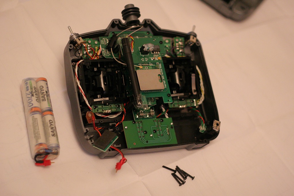
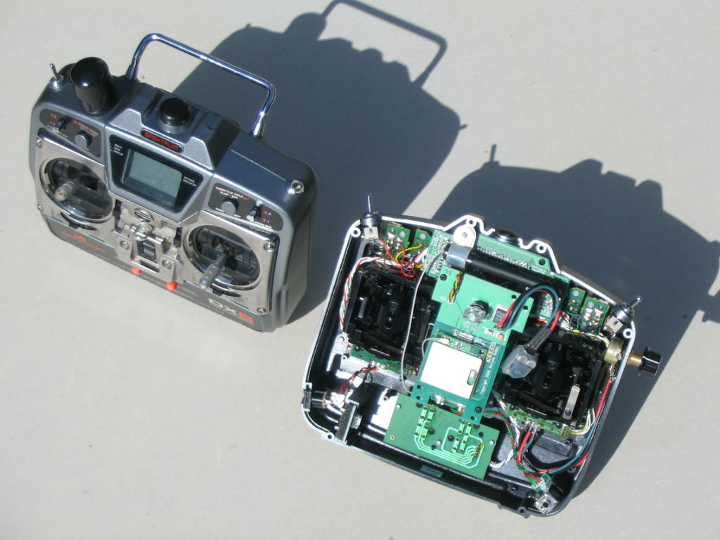
Here is the back cover and six screws that hold it removed along with the battery (I've put Deans connectors on the Tx battery to simplify charging). With a stock DX6 the antenna would be sticking out at the top and there would be a few extra pieces of black plastic supporting it. I remember I broke some of those black plastic parts when I disassembled the antenna - so proceed carefully if you think you want to go back to the stock configuration sometime. I didn't touch the electrical connection of the antenna at all, the thin grey coax that comes out of the antenna attaches to the RF PCB just like it does on the stock Tx.
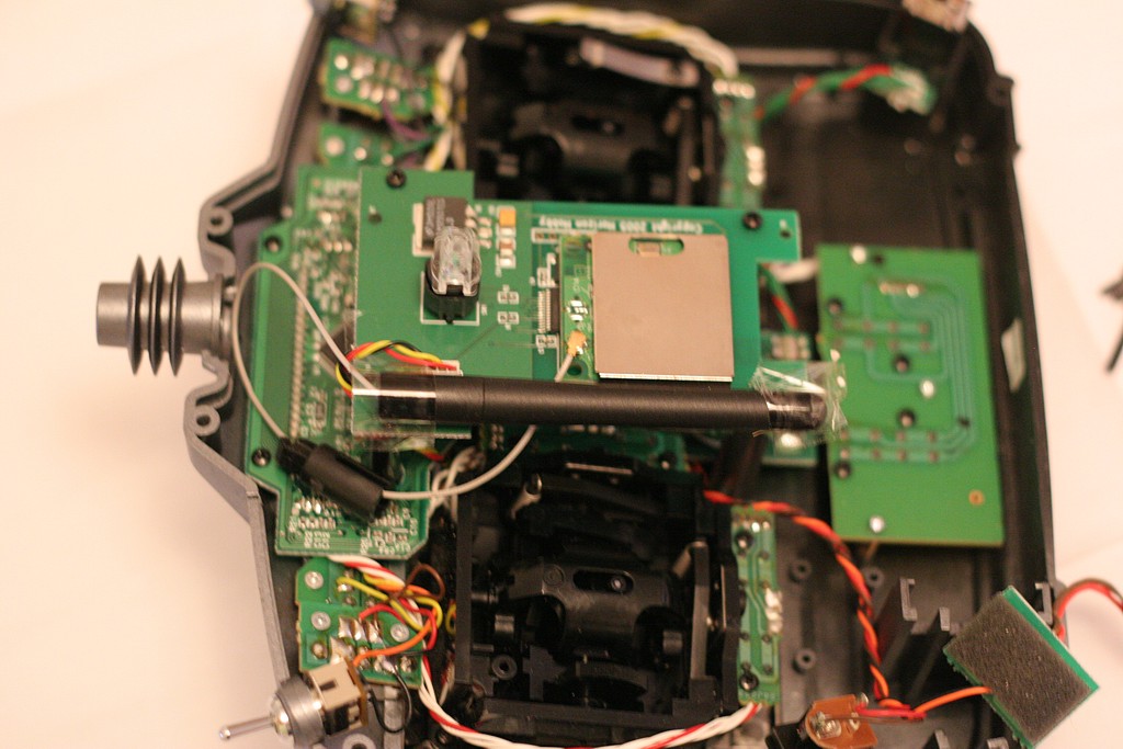
Here's a close-up of the antenna. You can see a part of the old antenna-hinge around the grey coax to the left (a bit dangerous to cut it away with a knife or pliers since you risk damage to the delicate coax). I've taped the antenna upside down to the RF board. There are probably other places inside the case the antenna could fit as well, but this seems to work OK.
If anyone has done something similar do let me know! I'd be happy to post pictures here if you send them to me.
Spektrum: I hope you are taking notes, I expect your next radio to have an internal antenna!
Talking about DX6 modifications, I did order the voltage regulator for the improved runtime modification, but the runtime with 2700 mAh NiMH's is just fine so I haven't installed the improved regulator yet.
Update 2007Nov17:
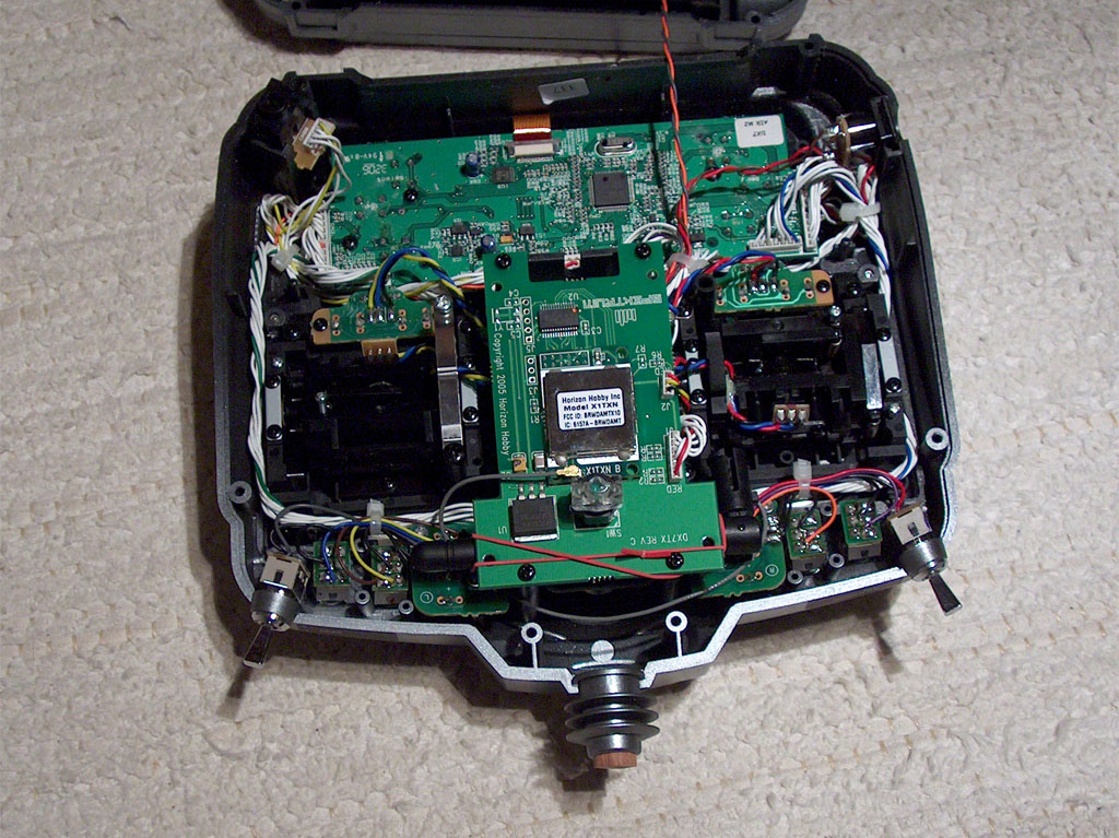
Olle Martonen sent me this pic of his modified Spektrum DX7. He mounted the antenna horizontally behind the regulator/switch PCB. Also note the wooden plug in the antenna hole. Not much sailing done with this system yet, but range-checking on the ground indicates there should be no problems.
I also got some observations be email on RF issues from a mobile-phone perspective: A few mm of plastic will not attenuate the signal measurably. Conducting materials are worse, like some mobile phone shells that are covered with carbon-containing paint, or your fingers on the back side of the transmitter. My placement of the antenna close to the RF-box (the metal square), and the PCB (also metal-coated), is not optimal, and could lead to an attenuation of 3-5 dB. A distance of 2-3 cm to the conductive parts would be better, so I'll maybe look for other places inside the Tx where the antenna could fit (Olle's example above is a bit better since the antenna is farther away from the RF-box).
Update 2007Nov22:
Winston Mathews sent me this picture along with a description: "Here are our modified DX6 radios. 2200 mAh batteries, new voltage regulator, jib-trim potentiometer and now "internal" antennae (mounted horizontally). Range is unaffected. Thanks for the idea and your help. I would advise to install the voltage regulator. We can sail for two days without recharging. " Photo by Jack Wubble, owner of the open radio in the pic. Discussion on this is over at the EC12 discussion forum.
Update 2007 Nov 23:
Some text and images on modifying a Futaba 2.4 GHz radio on the EC12 website.


Stretching DNA

Some promising results yesterday with trying to stretch DNA molecules. The molecule is attached between two microspheres, and we are actively moving the smaller sphere while the force acting on the bigger sphere is being measured. The image and video shows the view through a 100x microscope objective on the optical tweezers instrument I am building. Towards the end you can see the construct breaking in two stages, so that probably means there were two molecules of DNA between the beads and not one as intended. This is a control experiment and will hopefully set the stage for bigger and better things to come...
Spinning the DC Servos
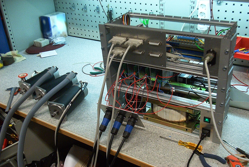
Some good steps towards driving our cnc-mill with DC-servos taken today. I got the pico-systems servodrives wired correctly, the new 50 kHz PWM m5i20 configuration loaded onto the fpga, and updated my pyvcp test panel a bit. I'm using three 19" rack enclosures. The lower one has a 1.8 kVA transformer, the middle one houses the servodrives, and the top one has differential encoder cards for the motors and optoisolator interfaces to the m5i20.
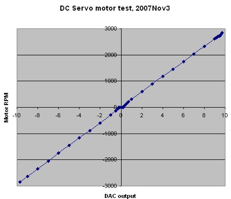
One small setback was that the servodrives wanted the PWM in reverse polarity compared to what I had available. There's nothing in the m5i20 driver to reverse the polarity of the DAC output PWM. Fortunately the drives have optocoupler inputs so instead of GND-PWM I wired them in a PWM-Vcc configuration and it worked OK. I did an open-loop no load test (below) where I monitored the RPM while changing the DAC output. There's a bit of dead-band in the middle where nothing happens between DAC values of about -0.2 and +0.2. After that the curve is pretty linear up to +9.7 after which the PWM pulse becomes unacceptably short for the servodrive and at DAC=9.8 or above the motors just jump and stutter. So eventually with EMC and PID control I need to limit the DAC range to [-9.7 , +9.7].
Next is probably trying out closed-loop PID control, and after that I need to look at the E-stop chain, home switches, a relay for the flood coolant pump, and controlling the VFD/Spindle.
IOMs on Blur.se
Swedish sailing blog Blur.se visited an IOM race in Gothenburg and did a report on the event and the IOM class.
The swedes now have about four boat producers, which will surely increase class numbers year by year: Meterboats (Khaa and Bagheera), Onemetrefun (Norlin-design), Azetone, and Sphincter,
Sepktrum DX6i, HiTec HSR-5990
Spektrum recently introduced an updated version of the DX6: the DX6i. Horizon Hobby also has an article on the new radio.
This one uses 'DSM2' technology which is described as giving 'full range'. Not sure what that means, but range should be better than with the first generation of 2.4 GHz radios, which at times was problematic (if you did something specific that cut down on the range).
I think the original DX6 was more or less a carbon copy of an existing JR transmitter, but the DX6i seems to be a new ergonomic design. Instead of buttons for navigating the menu it has a roller-device, and there's a new bigger LCD for programming.
The antenna still sticks out at the top even though nobody has had a mobile phone with an external antenna in years. I've mounted the antenna on my own DX6 inside the plastic case and it seems to work fine. I predict and hope that the next version in 1-2 years from spektrum will have the antenna mounted inside the Tx (no fear of breaking it, no problems with leaking rain-covers).
It's going to be in stores in December, for around $180 without servos, which is similar to what the 6-channel 2.4 GHz Futaba sells for.
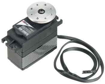
HiTec has replaced their previous robot servo (HSR-5995, now discontinued) with a new version called HSR-5990. The specifications are roughly the same as for the old model: torque is 24.0 or 30.0 kg.cm depending on if you use a 6 V or 7.4 V battery, but speed is down a bit from 0.15s/60deg to 0.17s/60deg (6 V). The gears are Titanium alloy, and as is visible from the picture the new servo adds a heat-sink to the casing.
Maybe this is the winch for my next boat? At a cost around $110, weight of 68 grams, and 'ludicrous speed', it looks like a strong alternative to a drum-winch. Anyone have good or bad experiences with the 5995 or the new 5990?