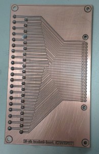
Making break-out boards is not exactly rocket science... Oh well, this one is required for a 10-channel temperature measurement which we do with pt100 sensors and a 4-wire multimeter. It's great however to have a working toolchain where you come up with an idea in the morning, spend a few hours designing the schematic and PCB, then go over to the PCB-mill and run the CAM-programs to produce the PCB, and assemble and test your circuit by the end of the day.

"It's great however to have a working toolchain where you come up with an idea in the morning... and test your circuit by the end of the day."
That does sound great 🙂
I have a CNC router controlled by EMC2.
What's (the rest of) the tool chain?
At work the toolchain is:
schematic - PADS PowerLogic
PCB - PADS PowerPCB
CAM - CircuitCAM
CNC - BoardMaster (which runs an LPKF PCB-router)
For DIY PCB-making I would guess getting the z-height of the tool right will be challenging. The LPKF uses a system where the spindle has a plastic ring around it which is pushed into contact with the PCB. The tool-length then determines how far into the PCB the tool reaches.
I've never owned a PCB-router of my own so I haven't really looked into an open-source toolchain. http://www.geda-project.org/ should go a long way. I'm not sure about the CAM-part, i.e. producing G-code from gerbers. My work on openvoronoi might be useful there..