Were stretching a 13 kb DNA-construct between two optically trapped beads. This isn't a video of the experiment itself, but of some entangled beads we found in an old sample. The beads are 3 or 2 micron in diameter, and we hold on to the middle big bead with the optical trap while moving around the microscope stage. Hydrodynamic drag stretches out the chain of entangled beads. Not much, if any, scientific value, but a fun video nevertheless.
Tag: video
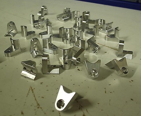
Aluminium milling video
As promised, the video of the roughing + finish operation on the finderscope-ring drilling jig.
Bulb Milling Videos
Jari shot some videos during the milling of the beaver-tail bulb. They now appear on YouTube.
For a mostly home-built cnc minimill of this size, this is pretty 'hard core' stuff...
Bulbs of Steel
As a first serious test-run for our now servo-controlled cnc mill we decided to make an IOM bulb out of steel. It ends up a bit bigger in volume when made out of steel compared to lead, but the difference isn't huge. Making it with a cnc mill allows designing almost any reasonable 3D shape you can imagine.
The mill worked fine during the whole run, about 3 hours of rough-cutting and 1.5 hours of finish cutting, but there was a slight operator error in the setup which means this bulb will likely not sail. The following error stayed low throughout the run, and the servos weren't even hot to the touch after the workout.
We used adaptive roughing paths and then a simple parallel finish path. Both operations are cut with an 8 mm flat cutter. The adaptive paths did seem to work, and on this size machine they are really handy since a slight over-cut will likely stall the spindle motor (1.5 kW and 5000 rpm, small by big-iron cnc-standards).
0:00 rough cutting begins. The stock is a 45 mm diameter steel bar, face-milled down on the sides so it can be clamped to the machine vises. Note the cutting feedrate which is 500mm/min and 'high-feed' in the (x,y)-plane when the tool is positioned for the next cut. When the tool lifts up to the clearance plane it does normal G0 (rapid) moves.
1:34 more rough cutting on the other end of the bulb.
1:58 still pics of the rough-pass almost ready
2:15 view of emc2 while cutting. Note pyVCP bar widgets showing commanded PWM to servo motors.
4:29 beginning of parallel finish cut. programmed feed 1500 mm/min which is attained briefly in the middle of the move.
5:00 more finish cutting, about 2/3 done.
5:50 another view of emc2 and the pyVCP panel. Note Y and Z motors working to position the tool. The following error for each axis is also shown.
6:15 still pictures of the finished bulb (well, one half of it anyway). Note at the front of the bulb we tried to run the program at 150% of programmed feedrate, but that didn't work at all and resulted in a poor surface finish. We did try to slow down also from 100% but that didn't improve the surface much.
Google video doesn't really do justice to the nice 640x480 video and 5 Mpix still-photos that come out of the N95, so if you've bothered to read this far, here's the original 100 Mb mp4 (I hope I don't exceed my bandwidth limit).
Trimaran on Foils
A fast but unstable way of radio-sailing.
Stretching DNA

Some promising results yesterday with trying to stretch DNA molecules. The molecule is attached between two microspheres, and we are actively moving the smaller sphere while the force acting on the bigger sphere is being measured. The image and video shows the view through a 100x microscope objective on the optical tweezers instrument I am building. Towards the end you can see the construct breaking in two stages, so that probably means there were two molecules of DNA between the beads and not one as intended. This is a control experiment and will hopefully set the stage for bigger and better things to come...
More milling videos
Jari upgraded the spindle motor to 1.5 kW and shot a few more milling videos.
movie 1:
movie 2:
movie 3:
movie 4:
Finished parts:
Opti-BF20 in action
Jari has made an enclosure around our cnc-mill, and that allows us to use a liberal amount of flood coolant. Here's a short video with some tests in aluminium.
Before you run to the shop and get an Opti-BF20 of your own please remember that our machine is seriously modified. We put a new table on it with linear guides, we're using ballscrews, and the stock spindle and spindle motor are replaced.
An emergent spiral
Most conventional CAM algorithms are geometry-based. They create toolpaths that are usually parallel to either the coordinate axes ('zigzag'-paths) or to the part contour (contour-parallel, or spiral paths). One problem with this geometry-based stuff is that you don't take into account the cutting forces. The algorithm has no idea about how much material is removed while the tool is moving. A quick patch is to run a cutting simulation after the path is created and adapt the feedrate for constant material removal rate (MRR).
Another option is to base the toolpath algorithm on a stock model. Then you know the shape of the stock at all times and you can control the MRR or cutter engagement angle. To quickly test how this could work I made a small test in matlab.
The cutter (green circle) is moved around by some rules, and cut's the red pixels as it travels over them. Cut pixels are drawn in blue. The cutter is moved around in discrete steps in some direction, and you're only allowed to cut a certain number of pixels per move. The tricky part is coming up with the rules for our 'lawn-mower' robot. Now I'm using a simple idea: If the past move was made at an angle alfa, try to take the next step in the same direction, but if that's not possible increase alfa until the MRR goes down to some preset value.
This idea will need refinement so that the robot can cope with walls, can do cutting in only one direction (climb vs. conventional) etc. etc., but this seems like a promising and fun start!
AOD Steering
I've worked on steering our Optical Tweezers instrument using Acousto Optical Deflectors. Here's an example of what it can do. We're trapping four 1 um silica microspheres in water using a single 1064nm laser that is time shared between the beads (it hops between them at a fast rate). Then we can program the AODs to steer the beads around in whatever patterns we want.