40-channel RF multiplexer

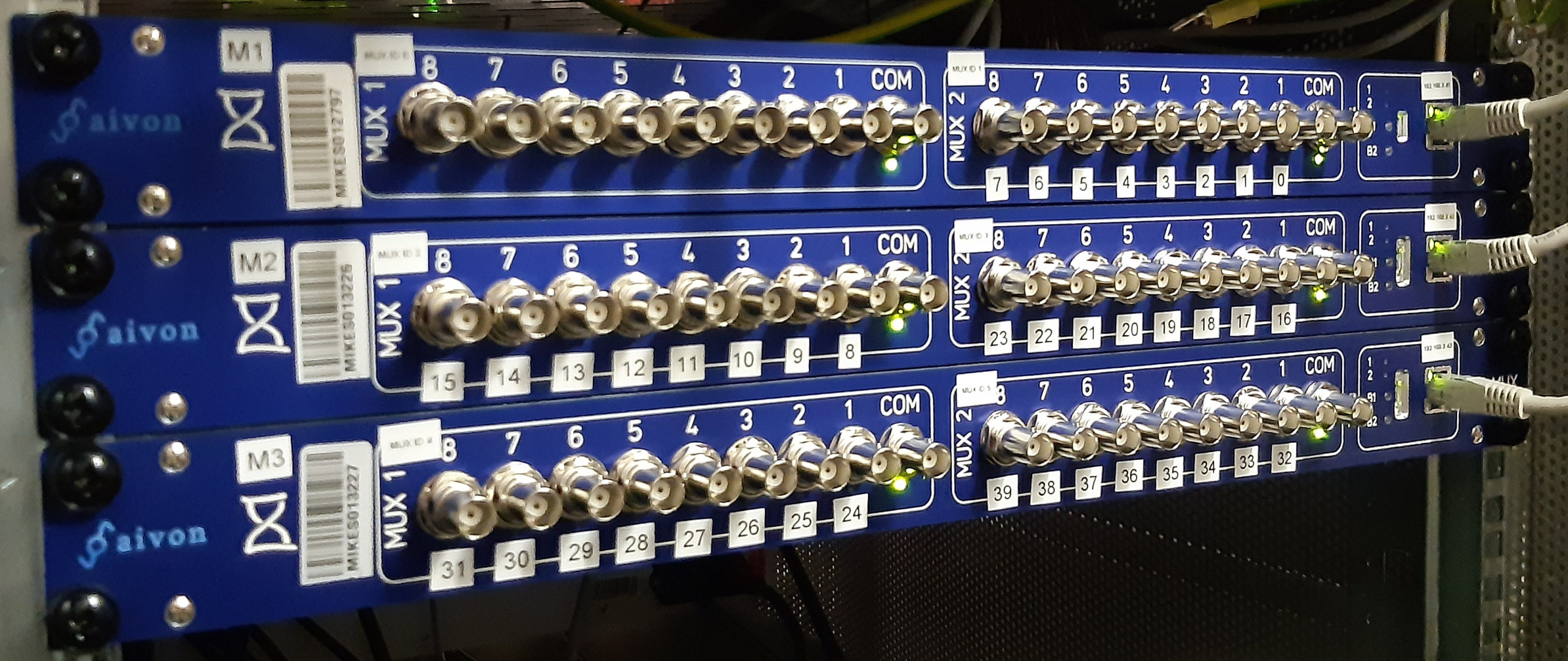
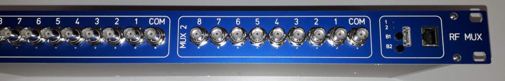
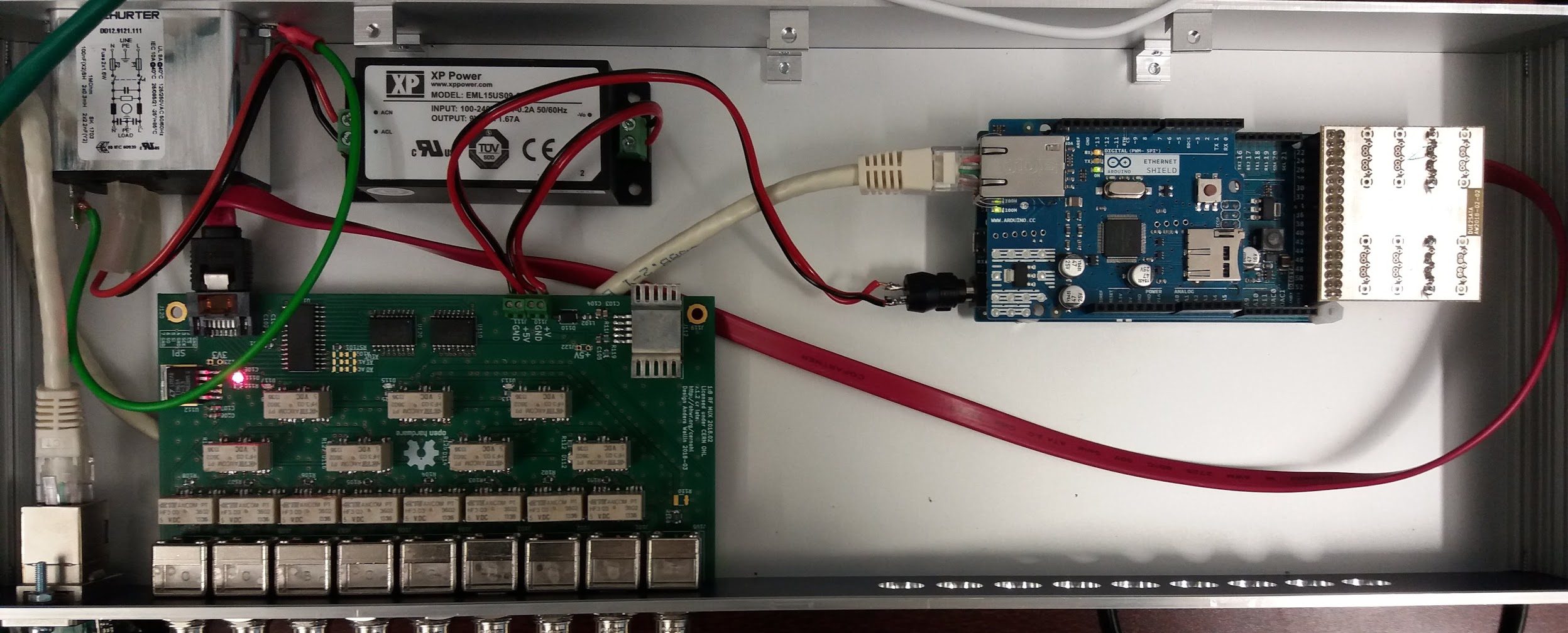
Just installed three of these 1U dual-1:8 RF-mutliplexers in the lab to make a 40-channel 1PPS measurement system. These are built by Aivon.

Time will tell how robust these are and if there are any failures in continuous use... Initial results from the field are good however.

We connect these in a depth-2 tree. One 1:8 mux is the top-level switch, with the remaining 5 providing 40 input-channels. This easily expands to 64 channels by adding one more 1U box. Beyond that I guess a depth-3 tree connection is required.

Multiplexer S/N 4

Slight design changes to the RF Multiplexer design.

Front panel buttons B1 and B2 now extend out of the front-panel and are easily accessible. Pressing the buttons advances the state of the MUX1 and MUX2 boards.

Transmission bandwidth. This MUX has 50-Ohm impedance relays, and the 3dB bandwidth is around 1.0-1.2 GHz.
Inside of MUX-box. Two 1:8 boards with BNC connectors side-by-side. Arduino MKRZERO and Ethernet Shield on the right. A simple carrier board distributes SPI-signals from the Arduino to the MUX-boards and provides front-panel pushbuttons and LEDs. Top center is a 230VAC to 5VDC powersupply. Top left 230VAC input.

Mux-in-a-box

Update: Insertion-loss measurement with a spectrum analyzer:

RF-multiplexer v2 board in enclosure, controlled by Arduino Due with Ethernet Shield. SATA-cable for 4 SPI-lines (SI, SO, SCLK, CS).

When issuing commands to change state as fast as possible this combination seems to do a state-change in about 45 milliseconds - this is not verified on the RF-side (didn't measure that there is actual RF contact made/broken in those 45 ms).

RF Multiplexer - version 2

Version two of the RF Multiplexer adds more relays to the 8 pcs HF3 I was using in the first attempt. The added relays keep the RF-path from the selected input to the COM-output as clean as possible with no unterminated branches or stubs. The cost is anothe 7 relays with associated darlington-drivers and control-logic.

Next test is to see if there is any measurable change to the rise-time of a fast pulse-edge, e.g. from a distribution amplifier.

RF Multiplexer - first try

And now an entry in the "Plan to throw one away" section.

RF Multiplexer, 8 inputs, 1 output, BNC-connectors, TE HF3 relays specified to 3 GHz, an ULN2803A to pull the relay-coil, and an SPI I/O expander to drive the ULN - should be easy - right?

Well no, PCB trace-geometry does strange things beyond VHF. I clearly don't grok UHF very well.

Onward towards version 2! (any thoughts and advice on simulation or trace-geometry optimizers appreciated!)