Laser cut plywood test-project: a 2V geodesic sphere, diameter 200mm. Next is sanding the triangles a bit and then figuring out how to connect them neatly together.
Tag: laser
Laser cutting
First try at using the 50W CO2 laser cutter at the Iso Omena library. Material is 4mm Birch ply (K-rauta). I didn't have time to optimize the speed/power settings, so the edge-finish is quite burned, and a flame appears from time to time. There was a 3M tape-film (?model?) available, which when taped over the plywood-to-be-cut should reduce burning and flaming - but I didn't have time to try it.
Workflow: DXF files exported from CAD, the into Adobe Illustrator, set all linewidths to 0.01mm, then save as PDF, then print from Adobe Acrobat to the Epilog printer-driver, set speed/power for the material, send to the machine, set the (0,0) coordinate (top left) for the job, and press Go!
Butterfly laser diode mount
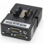
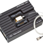
We've put together a few of these butterfly laser-diode mount + driver combos. It combines a heat-sinked butterfly mounted laser-diode with a current/temperature controller by Wavelength Electronics. The assembly is low enough to fit into a 1U (~44 mm) high 19" rack-enclosure.
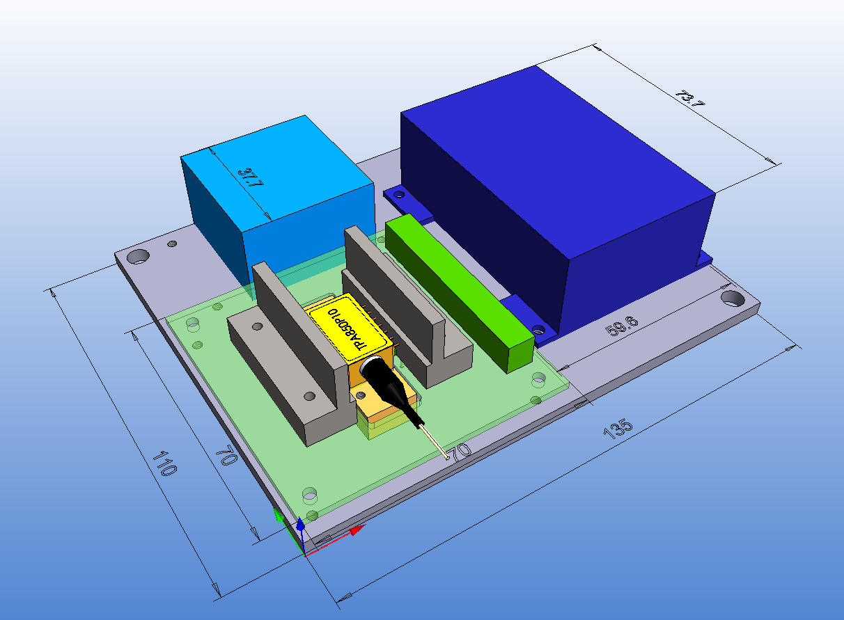
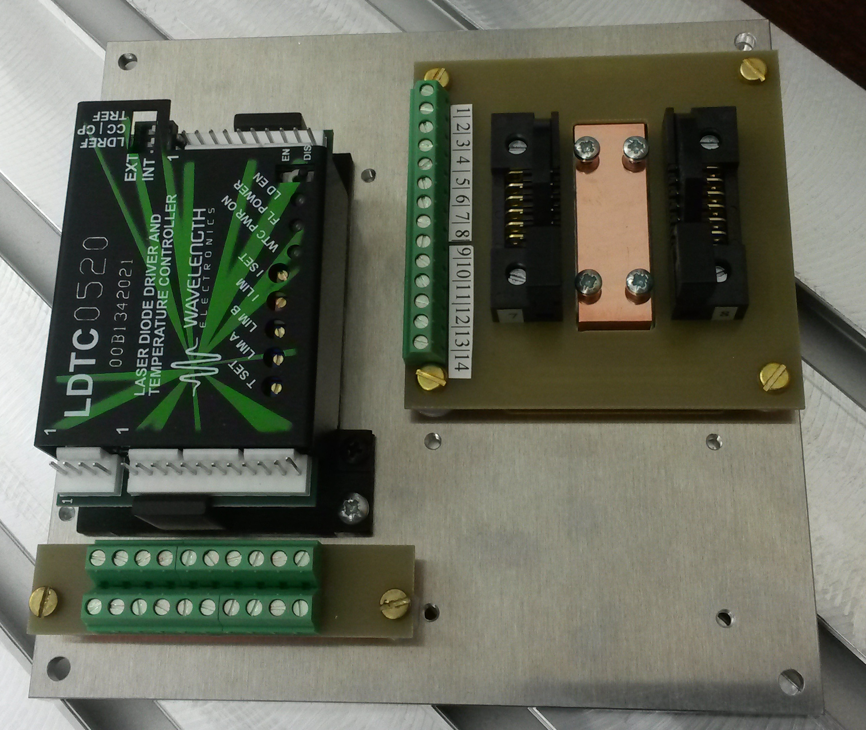
The 14-pin laser-package (yellow) is held in place by ZIF clamps/sockets 5253-100-07S (standard) and 5253-100-07R (reverse) from from Azimuth Electronics (grey in the CAD drawing, black in real life). The Wavelength Electronics LDTC driver controls both the laser current and temperature using the laser's own on-board TEC and thermistor. The base-plate has additional room for a heatsink and a fan, but so far I think nobody has used this feature. Semiconductor lasers have about 30% efficiency, so with anything under 1 W of optical output the dissipated heat should stay below 3-5 W.
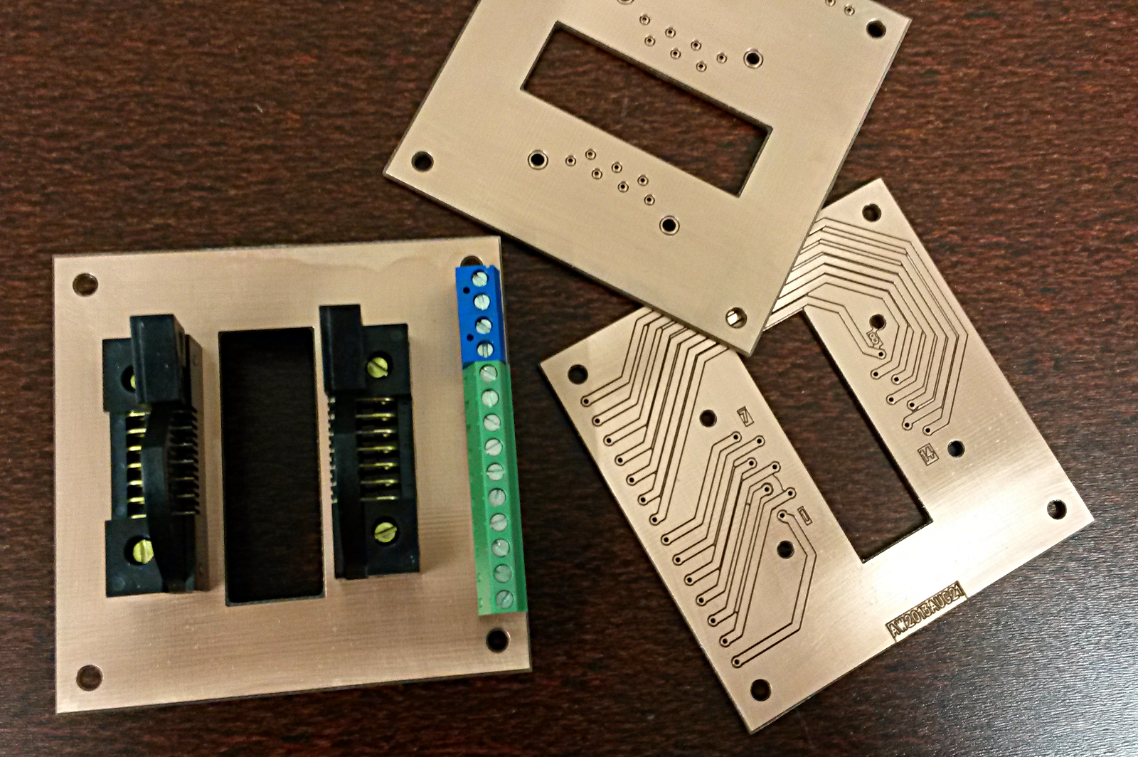
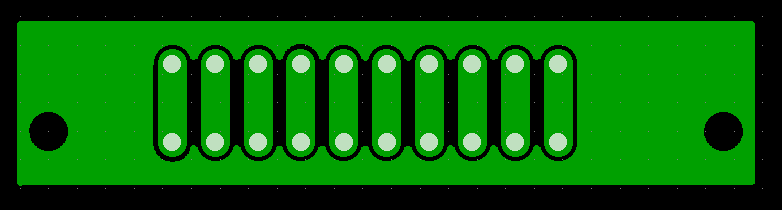
The metal parts are an aluminium base-plate (see bfly_mount_v1_plate_2013aug26 and the newer bfly_mount_v2_plate_2013nov1). A copper riser-block (bfly_mount_v1_riser-block_2013aug26) sits on top of the base-plate and provides good heat-conduction from the laser package to the base-plate. The riser-block and the laser are bolted together with M2.5 bolts/screws (allen-bolts would be more stylish - I know!). I also made a mechanical drawing for the PCB bfly_mount_v1_pcb_drawing.
The PCB has no electronics on it (see bfly_mount_v1_schematic_2013sep3), the pins from the Azimuth sockets are just routed to 150 mil pitch screw terminals.
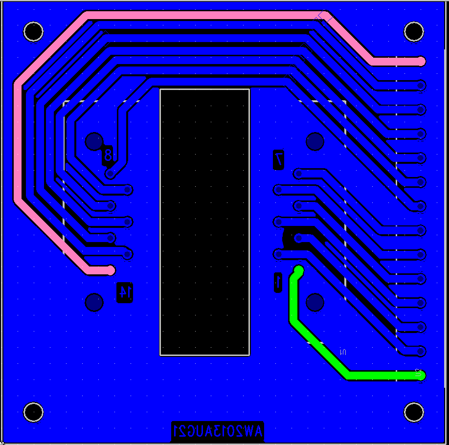
See also gerbers for manufacturing: butterfly_pcb_v1_camfiles or the slightly modified version dated 2013-11-14 butterfly_v3_camfiles
There's an additional mini-pcb for screw-terminals on the input side of the LDTC controller. screwterminal_camfiles_2013-09-12
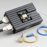
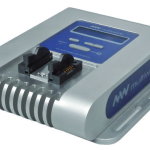
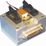
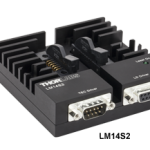
Our in-house design won't win any prizes for design or style, but it does the job. Here are a few pictures of commercial butterfly mounts. Some combine the current/temperature driver with the mount, others just have D-sub connectors for external current/temperature controllers.
Strontium Blues
We've been playing with a blue laser at 461 nm in the lab lately. If tuned to just the right frequency (wavelength) neutral Strontium atoms will strongly absorb the laser light. Shortly (5 nanoseconds) after that the atoms emit at 461nm also, allowing us to see them:
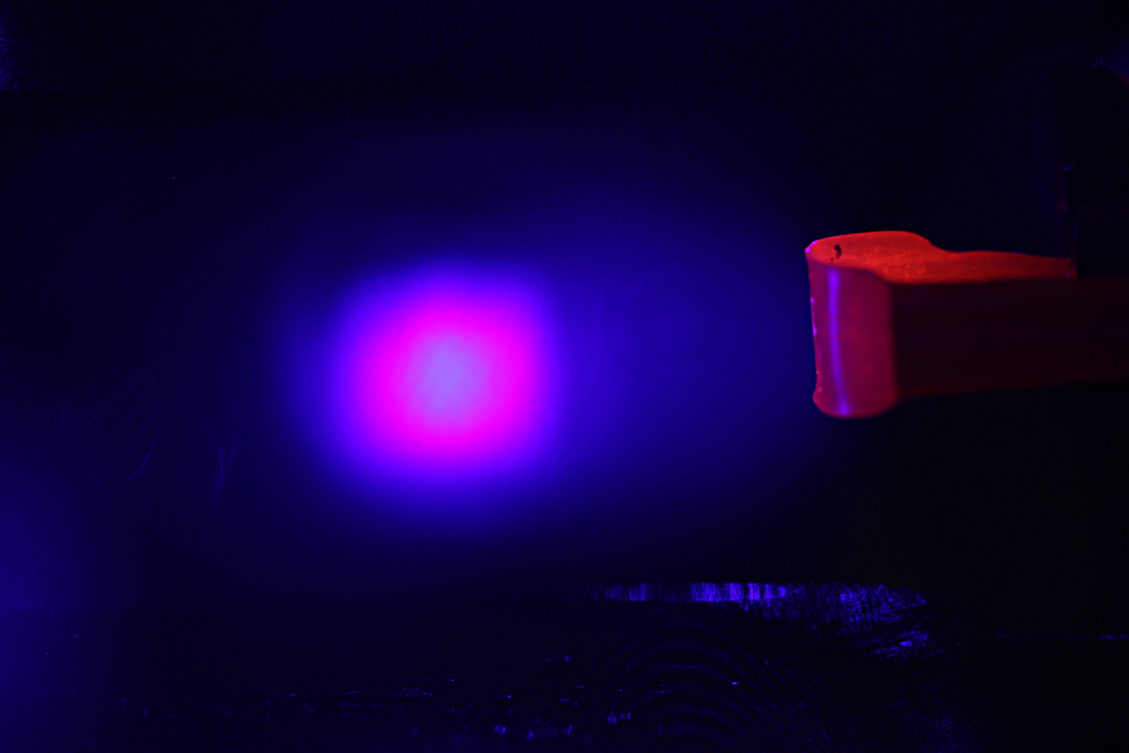
The atoms originate from a hot "oven" at the right. It glows dark red because it's heated by driving a 5 A to 7 A current through it. The cloud of absorbing atoms glows at 461nm in the centre of the picture.
We can scan the laser frequency by adjusting the current through the diode-laser that produces the light. If the frequency is too low or too high we'll see nothing as the light will just pass through the cloud of atoms without interacting. On each side of the correct absorption frequency we'll see different parts of the atom cloud light up. This happens because the atoms stream out of the oven in slightly different directions, so they experience a different Doppler shift and will react to light with a wavelength slightly to the blue or red from the centre of the absorption-line at 461nm.
When slowly scanning the laser frequency over the absorption-line we got these nice videos. One with a narrow beam and one where the laser beam was expanded.
These were shot with a Canon DSLR so be sure to view them in HD on youtube!
TEC mount for laser-module
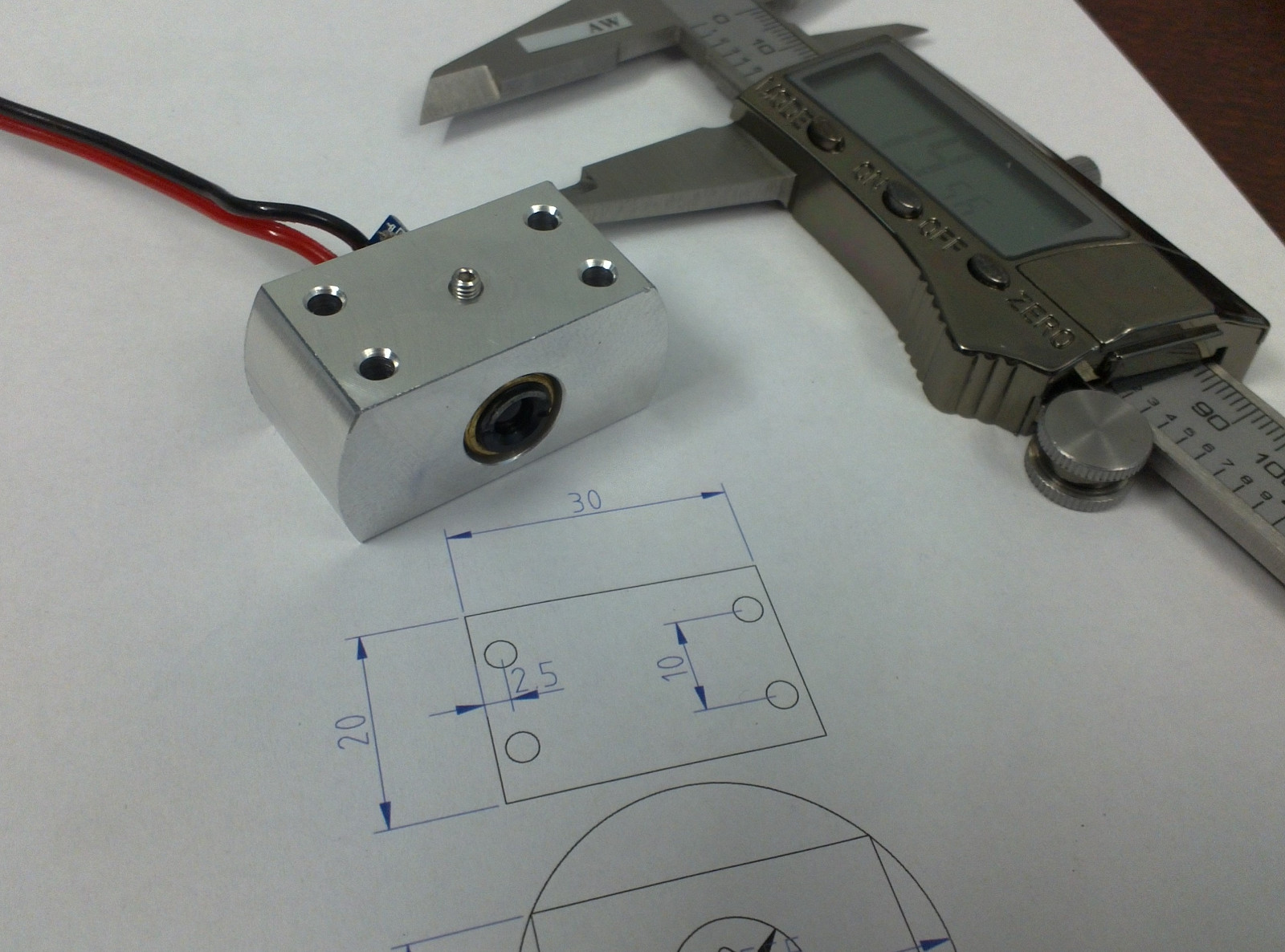
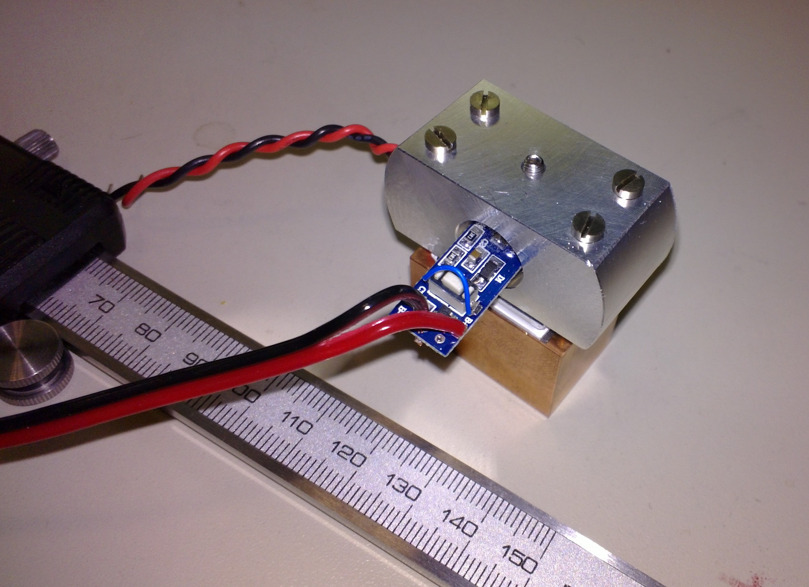
I made this aluminium bit on the lathe/mill today. It holds a blue laser-module from dealextreme. The brass barrel measured about 11.81 to 11.84 mm in diameter so I first drilled a 10mm hole, then opened it up slowly on the lathe until the module just fit the hole. There is an M3 set-screw to hold the laser module in place. Four long M2.5 screws clamp the aluminium part into contact with a peltier-element and the copper heatsink. A thermistor for temperature measurement and feedback control will be glued to the aluminium part as close as possible to the peltier.
Temperature control of the laser diode should provide for rough tuning of the laser wavelength. We want the wavelength to be about 405.2 nm, to be used for photoionization of Strontium.
Aside: A few years ago I tried to order some of these 405nm laser-pointers to the university. It was impossibly difficult because the shipments were stopped by the customs. Negotiations with the radiation-safety authorities did not help. It's simply forbidden to import non CE-approved laser-pointers - it doesn't matter if you are a researcher or work at a research institution. The story is completely different for laser modules (this is exactly the same product as the laser-pointer, but without the pen-like shape and the battery holder). Apparently these are classified just as "diodes" or "electronic components" and there are no problems getting them through customs.
Measuring the thermal expansion of ULE glass
Here's an experiment I've done recently:
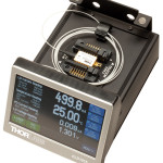
(Time-lapse of ca 18 hour experiment. Bottom left is a spectrum-analyzer view of the beat-note signal. Top left is a frequency counter reading of the beat-note. Bottom right is a screen showing the a camera-view of the output-beam from the resonator)
This is a measurement of the thermal expansion of a fancy optical resonator made from Corning "Ultra Low Expansion" (ULE) glass. This material has a specified thermal expansion of 0.03 ppm/K around room temperature. This thermal expansion is roughly 800-times smaller than Aluminium, around 400-times smaller than Steel, and 40-times better than Invar - a steel grade specifically designed for low thermal expansion.
Can we do even better? Yes! Because ULE glass has a coefficient of thermal expansion (CTE) that crosses zero. Below a certain temperature it shrinks when heated, and above the zero-crossing temperature it expands when heated (like most materials do). This kind of behavior sounds exotic, but is found is something as common as water! (water is heaviest at around 4 C). If we can use the ULE resonator at or very close to this magic zero-crossing temperature it will be very very insensitive to small temperature fluctuations.
So in the experiment I am changing the temperature of the ULE glass and looking for the temperature where the CTE crosses zero (let's call this temperature T_ZCTE). The effect is fairly small: if we are 1 degree C off from T_ZCTE we would expect the 300 mm long piece of ULE glass to be 200 pm (picometers) longer than at T_ZCTE. That's about the size of a single water-molecule, so this length change isn't exactly something you can go and measure with your digital calipers!
Here's how it's done (this drawing is simplified, but shows the essential parts of the experiment):
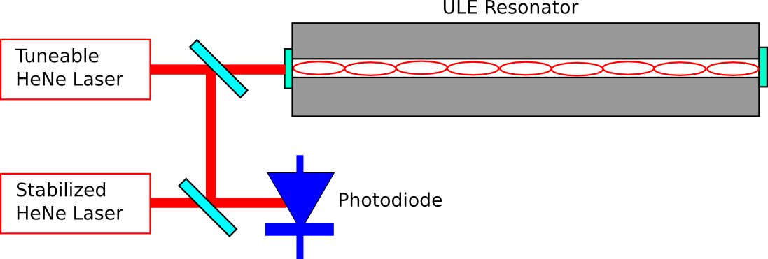
We take a tuneable HeNe laser and lock the frequency of the laser to the ULE-cavity. The optical cavity/resonator is formed between mirrors that are bonded to the ends of the piece of ULE glass. We can lock the laser to one of the modes of the cavity, corresponding to a situation where (twice) the length of the cavity is an integer number of wavelenghts. Now as we change the temperature of the ULE-glass the laser will stay locked, and as the glass shrinks/expands the wavelength (or frequency/color) of the laser will change slightly.
Directly measuring the frequency of laser light isn't possible. Instead we take second HeNe laser, which is stabilized to have a fixed frequency, and detect a beat-note between the stabilized laser and the tuneable laser. The beat-note will have a frequency corresponding to the (absolute value of the) difference in frequency between the two lasers. Now measuring a length-change corresponding to the size of a single water-molecule (200 pm) shouldn't be that hard anymore!
Let's say the stabilized laser has a wavelength of 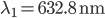 (red light). Its frequency will be
  (that's around 474 THz). When the tuneable laser is locked to the cavity we force its wavelength to agree with
  where
where  is an integer and
  is the length of the cavity. I've drawn only a small number of wavelengths in the figure, but a realistic integer is
  . We get
  and
and  , very nearly but not quite the same wavelength/frequency as the stabilized laser. Now our photodiode which measures the beat-note will measure a frequency of
  .
.
How does this change when the ULE glass expands by 200 pm? When we heat or cool the cavity by 1 degree C the length changes to 300 mm + 200 pm, and the wavelength of the tuneable laser will change to
 . Now our beat-note detector will show
  . That's a change in the beat-note of more than 300 kHz - easily measurable!
That's how you measure a length-change corresponding to the diameter of a water molecule!
Why do this? Some of the best ultra-stable lasers known are made by locking the laser to this kind of ULE-resonator. Narrow linewidth ultra-stable lasers are interesting for a host of atomic physics and other fundamental physics experiments.
See also: Janis Alnis playing with two ultra-stable lasers.
Update 2013 August: I made a drawing in inkscape of the experimental setup.
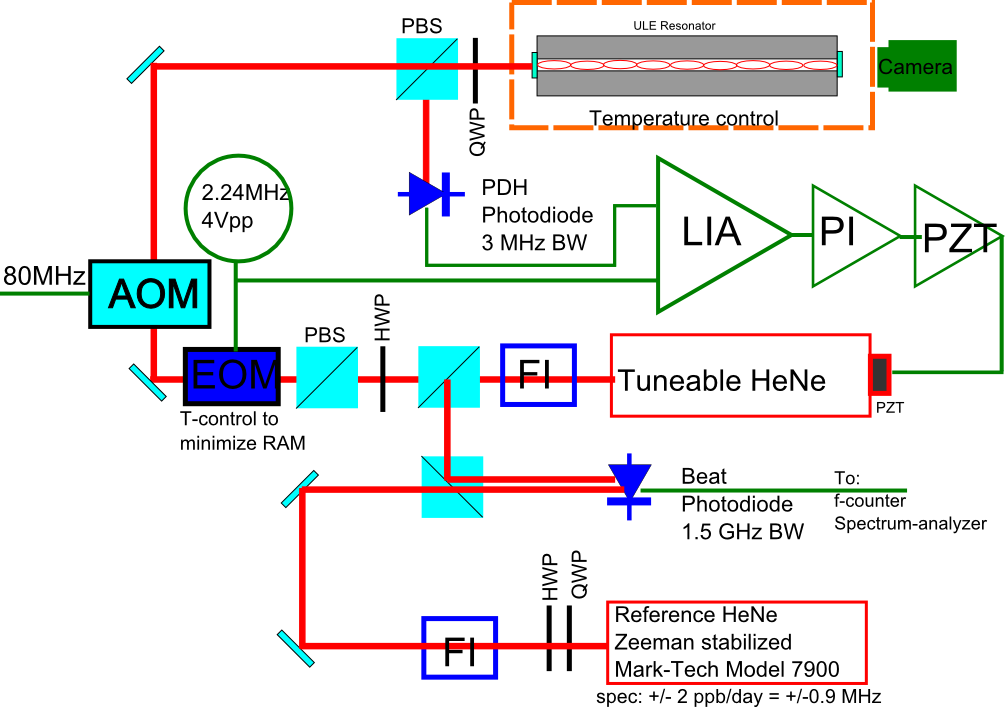
This figure shows most (if not all?) of the important components of this experiment. The AOM is not strictly required but I found it useful to shift the tuneable HeNe laser by +80 MHz to reach a TEM-00 mode of the ULE resonator. Not shown is a resonance-circuit (LC-tank) between the 2.24MHz sinewave-generator and the EOM. The EOM was temperature controlled by a TEC with an NTC thermistor giving temperature feedback.
Laser noise
I've been measuring the beat-note (wikipedia talks about sound-waves, but it works for light-waves too) between two HeNe lasers. It jumps around maybe +/- 5 MHz quite rapidly which is not nice at all:
One laser is a commercial stabilized laser (I've tried both a HP5501A and a Mark-Tech 7900), and the other laser is a tunable one which I want to use for my experiment. But with this much jumping around the tunable laser is no good for the experiment I want to do 🙁
Michelson interferometer
Tried this simple Michelson interferometer for measuring the error of a 100mm translation stage yesterday. The interferometer and stage are mounted to the same optical table, but there's still a fair amount of vibration of the measurement corner-cube which causes instability in the signal when the stage is not moving.

Some sample data here: interf_data. One channel is an encoder signal from the motor which should come every 5 um, the other channel is the interferometer output. Analysis will follow...
Colors


Green laser in Berlin

There's a seriously cool green laser on top of a Siemens building in Adlershof in Berlin.