EMC2 tpRunCycle revisited

I started this EMC2 wiki page in 2006 when trying to understand how trajectory control is done in EMC2. Improving the trajectory controller is a topic that comes up on the EMC2 discussion list every now and then. The problem is just that almost nobody actually takes the time and effort to understand how the trajectory planner works and documents it...

A recent post on the dev-list has asked why the math I wrote down in 2006 isn't what's in the code, so here we go:

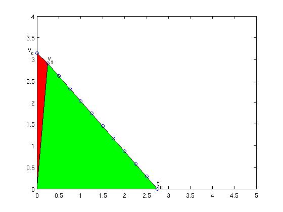
I will use the same shorthand symbols as used on the wiki page. We are at coordinate P ("progress") we want to get to T ("target") we are currently travelling at vc ("current velocity"), the next velocity suggestion we want to calculate is vs ("suggested velocity), maximum allowed acceleration is am ("max accel") and the move takes tm ("move time") to complete. The cycle-time is ts ("sampling time"). The new addition compared to my 2006 notes is that now the current velocity vc as well as the cycle time ts is taken into account.

As before, the area under the velocity curve is the distance we will travel, and that needs to be equal to the distance we have left, i.e. (T-P). (now trying new latex-plugin for math:) (EQ1)

Note how the first term is the area of the red triangle and the second therm is the area of the green triangle. Now we want to calculate a new suggested velocity vs so that using the maximum deceleration our move will come to a halt at time tm, so(EQ2):


Inserting this into the first equation gives (EQ3):


this leads to a quadratic eqation in tm (EQ4):


with the solution (we obviously want the plus sign)(EQ5)


which we can insert back into EQ2 to get (EQ6) (this is the new suggested max velocity. we obviously apply the accel and velocity clamps to this as noted before)


It is left as an (easy) exercise for the reader to show that this is equivalent to the code below (note how those silly programmers save memory by first using the variable discr for a distance with units of length and then on the next line using it for something else which has units of time squared):

discr = 0.5 * tc->cycle_time * tc->currentvel - (tc->target - tc->progress);
discr = 0.25 * pmSq(tc->cycle_time) - 2.0 / tc->maxaccel * discr;
newvel = maxnewvel = -0.5 * tc->maxaccel * tc->cycle_time +tc->maxaccel * pmSqrt(discr);

over and out.

EMC2 upgrade

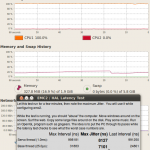
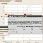
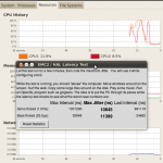
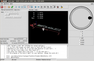
I've upgraded Ubuntu and EMC2 on the Atom 330 machine I have for controlling the lathe. The Atom 330 is a dual-core chip, but with Hyper Threading the OS can see four cores. That's not good for real-time performance, so the first thing I did was turn off HT from the BIOS. Next I did a distribution upgrade to 10.04LTS which downloaded about 1 Gig in an estimated 9 minutes (2Mb/s is OK I guess...). I then used the emc2-install script which installs the real-time kernel and emc2, and finally I edited /boot/grub/menu.lst by adding "isolcpus=1" on the kernel line. This reserves one cpu core for real-time and the other for non-real-time tasks. Without "isolcpus=1" the latency-test jitter values were easily 10k and more with a light load on the machine. With one core dedicated to real-time the jitter numbers start out at around 4k at light load and double to 7-8k under heavy load.

Here are some selected screenshots:

Next stop is getting the X and Z servos moving, as well as the hefty 2 kW spindle servo.

Mesa 5i20 breakout boards

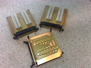
In 2006 I made optoisolator cards for the cnc-mill project, but now with the lathe I am using servo-drives and a VFD which mostly already have optoisolated inputs, so I will use these very simple breakout boards instead. There are two pitch-standards for the screw-terminals, an imperial one with a pitch of 5.08 mm (i.e. 0.2 inches), and a metric one with 5.0 mm pitch. These boards are for 5.0 mm.

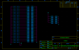
Pads logic and layout files: 2010_01_16_m5i20_breakout_board

Etch-mask (PDF): etch-mask


Atom330/ITX computer for EMC2 lathe-control

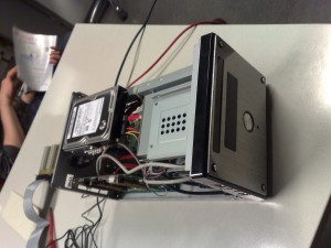
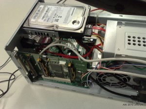
I put together this small computer which will be used to control the lathe. The components for this kind of box are quite inexpensive:
D945GCLF2 motherboard including 1.6 GHz Atom330 CPU, 76 eur
Codegen MX31 case including 420W PSU, 46 eur
2Gb DDR2 memory stick, 46eur
Samsung 320Gb HDD, 44eur
Labtec keyaboard + mouse, 17eur

Total:  229 eur (no display) parts from jimms-pc and verkkokauppa.com

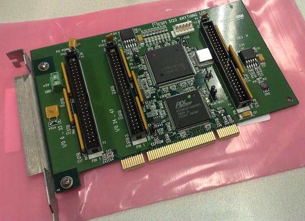
The motherboard has one PCI-slot for a Mesa 5I20 FPGA-card which provides 72 digital I/O pins for real-time control.

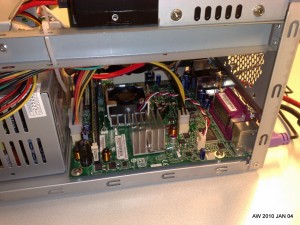
Here is the D945GCLF2 motherboard. The CPU doesn't need a fan, but there is a small fan for the PCI-controller(?).

Realtime performaceshould be OK, I was getting about 10 us of jitter for a 1 ms thread.

5-axis simulation

The people at EMC2 Fest (webcam here) made this AVI of 5-axis machining a sphere using some custom g-code and povray.

I've been playing around with vpython, so you can expect some CAM-related posts on drop-cutter in Python and associated 3D views or animations in the not too distant future.

Tiller arm machining

Here's a setup wit three vises for machining model yacht tiller arms. The parts are rotated 90 degrees between the first stage (leftmost) and the second stage (middle), and then again 90 degrees for the final stage (right). There's some rigid tapping at around 8:20.

Rigid Tapping

We've mounted a 500 cpr encoder on the spindle-motor which means it's possible to do rigid tapping. Above some spot-drilling, then a 2.5 mm drill, and then an M3 tap at 500 RPM and 0.5 mm Z-feed per revolution. Below the same thing but with a 5 mm drill and an M6 tap (1 mm Z-feed per rev).

Cool stuff!