TEC-Drive v2

Sadly TEC-Drive v1 died an untimely death when it overheated due to being powered from +/-15 V instead of the designed +/-5 V.

TEC-Drive v2 is a simplified design using TO-220 packaged LM317/LM337 adjustable regulators and the OPA569 high-current op-amp.

tecdrive_v2_schematic

Constant-current drive is achieved using the OPA569 (U2) I_monitor output. I_monitor sources/sinks a fraction I_out/475 of the actual output current. By using another op-amp (U1) in a transimpedance configuration we get a feedback-voltage proportional to the output current.

PCB layout on a 100 mm x 160 mm eurocard:

tecdrive_v2_pcb


Built and assembled as a plug-in card for a 3U rack. Note big heatsinks on the +/-2.5 V regulators.

tecdrive_v2_assembled

The DC-response is I_out = 105 mA/V * V_in, with an offset at zero-input of -4 mA.

tecdrive_v2_dc-response

With no low-pass capacitors (C1 at the input, and C11 over the transimpedance-resistor) added and a purely resistive load the frequency response extends beyond 1 MHz with some ringing.

tecdrive_v2_ac-response

Butterfly laser diode mount

We've put together a few of these butterfly laser-diode mount + driver combos. It combines a heat-sinked butterfly mounted laser-diode with a current/temperature controller by Wavelength Electronics. The assembly is low enough to fit into a 1U (~44 mm) high 19" rack-enclosure.
bfly_mount_v1_assembly_2013sep3 bfly_mount_v2_assembled

The 14-pin laser-package (yellow) is held in place by ZIF clamps/sockets 5253-100-07S (standard) and 5253-100-07R (reverse) from from Azimuth Electronics (grey in the CAD drawing, black in real life). The Wavelength Electronics LDTC driver controls both the laser current and temperature using the laser's own on-board TEC and thermistor. The base-plate has additional room for a heatsink and a fan, but so far I think nobody has used this feature. Semiconductor lasers have about 30% efficiency, so with anything under 1 W of optical output the dissipated heat should stay below 3-5 W.

The metal parts are an aluminium base-plate (see bfly_mount_v1_plate_2013aug26 and the newer bfly_mount_v2_plate_2013nov1). A copper riser-block (bfly_mount_v1_riser-block_2013aug26) sits on top of the base-plate and provides good heat-conduction from the laser package to the base-plate. The riser-block and the laser are bolted together with M2.5 bolts/screws (allen-bolts would be more stylish - I know!). I also made a mechanical drawing for the PCB bfly_mount_v1_pcb_drawing.

The PCB has no electronics on it (see bfly_mount_v1_schematic_2013sep3), the pins from the Azimuth sockets are just routed to 150 mil pitch screw terminals.

bfly_mount_v1_pcb_2013sep3bfly_mount_v1_pcb_assembled

See also gerbers for manufacturing: butterfly_pcb_v1_camfiles or the slightly modified version dated 2013-11-14 butterfly_v3_camfiles

screwterminal_pcb

There's an additional mini-pcb for screw-terminals on the input side of the LDTC controller. screwterminal_camfiles_2013-09-12

Our in-house design won't win any prizes for design or style, but it does the job. Here are a few pictures of commercial butterfly mounts. Some combine the current/temperature driver with the mount, others just have D-sub connectors for external current/temperature controllers.

TEC Drive in enclosure

The TEC drive I have been working on is now mounted as a plug-in card in a 3U 19" rack enclosure like this:

tec_drive_rack_mounted

The card next to the TEC drive holds an 80 mm fan which helps cool the heatsinked linear regulators and the linear H-bridge that drives the TEC.

tec_drive_rack_backpanel

The back of the 19" rack enclosure holds two TRACO POWER PSUs that produce +/-5 V at max 4 A and +/-15 V at max 667 mA. An IEC power-entry module containing the IEC-connector, a fuse, and a power switch is visible far right. Far left is a small PCB for distributing +/-15 V to other cards in the same enclosure.

Added cooling allows testing the drive at the max input level of +/-10 V, which should produce (roughly) an output of +/-2 A.

tec_drive_test_2013sep23

The output current follows 179 mA/V * Vin + 1.8 mA with a maximum nonlinearity of about 6 mA (0.3% of full-scale). Despite the fan-cooling the transistors still get quite hot and staying below 1 A output in continuous operation is probably a good idea.

TEC-Drive heat sinks

tec-drive_heatsinks_2013sep4

I made four heat sinks from aluminium L-profile for the linear TEC drive. Two 30 mm long for each side of the H-bridge (middle), and two 50 mm long for the voltage regulators(top right).

The regulators take 5 V input and produce 2 V, so they each dissipate 3V *ITEC Watts. The H-bridge dissipation is load-dependent, but for a low resistance load the dissipation is almost 2V*ITEC Watts. Here I am using a resistor (lower left) as a dummy load.

I tested the drive at 1 A for a few minutes, and the heat sinks do get quite warm. For continuous use at 2 A I think a fan will be required.

TEC-Drive prototype

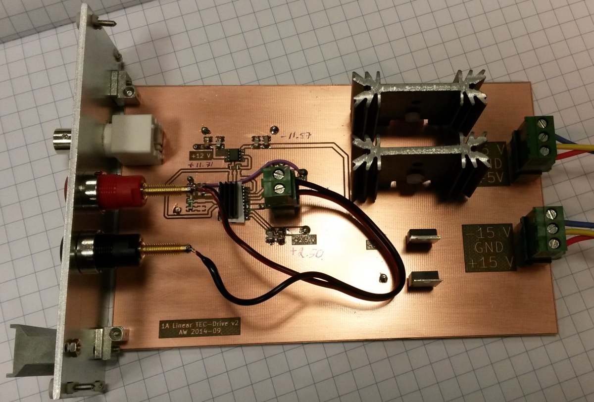
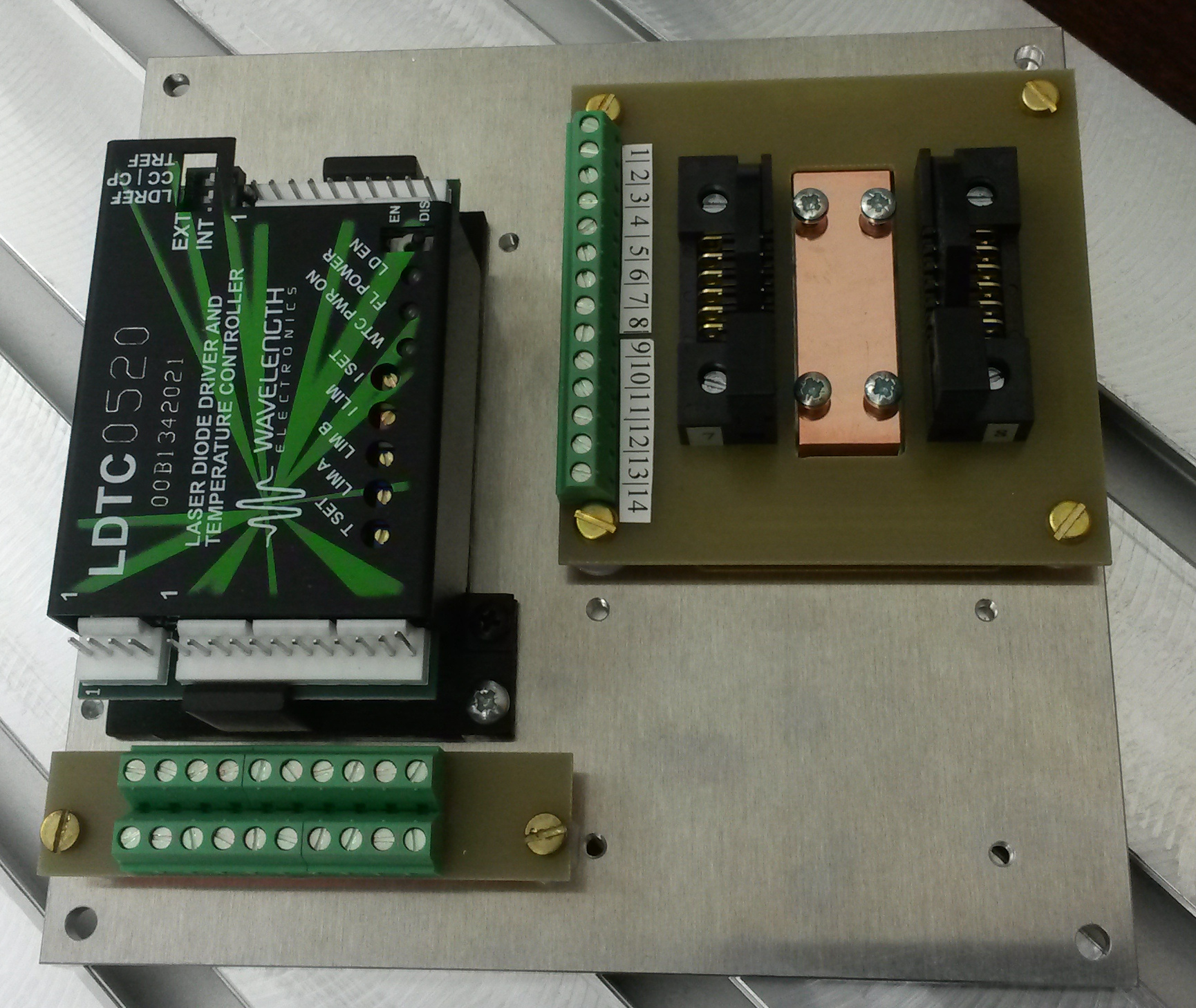
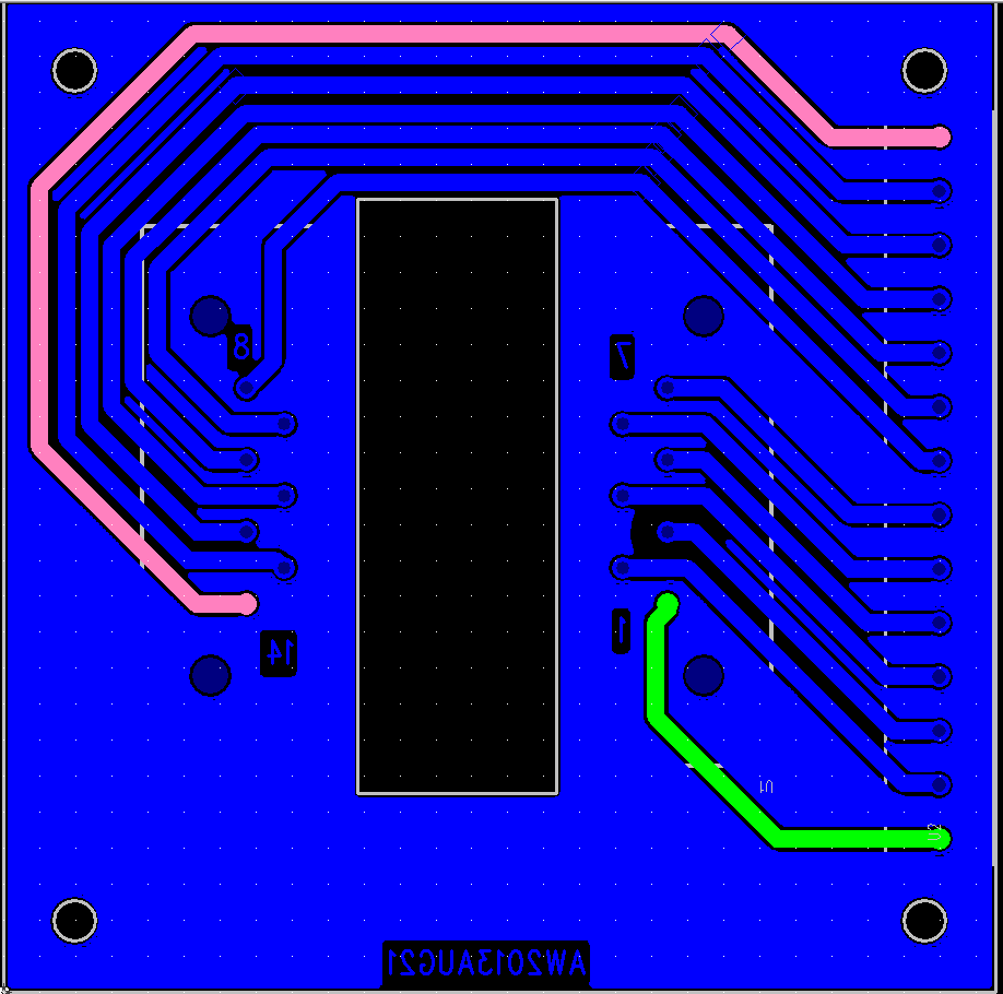
I've been assembling and testing this PCB over the past few days:

tec-drive_prototype_2013_08_01

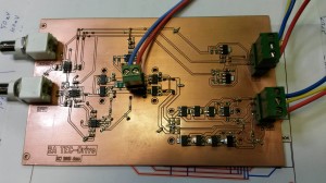
It's a linear +/-2 A voltage-to-current amplifier meant for driving a constant current through a Thermoelectric Cooler (TEC). The circuit is (loosely) based on a 2001 Burr-Brown/TI application note "SBEA001 - Optoelectronics Circuit Collection".

sbea001_tec-drive_v3

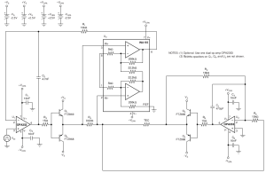
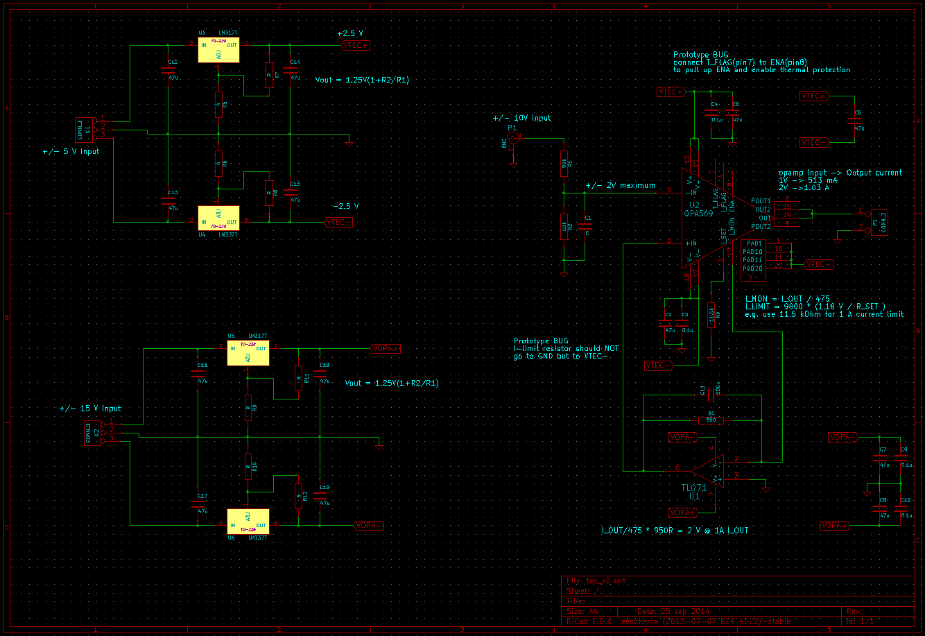
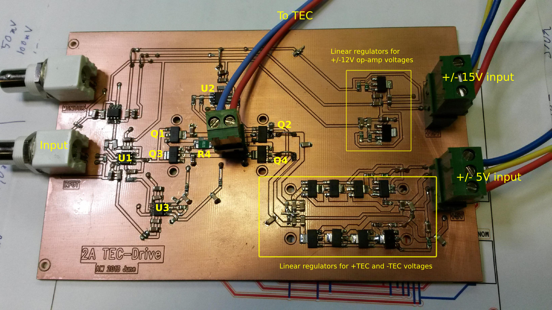
Description: U1 drives one half of the H-bridge (Q1 and Q3) based on a feedback signal which is the amplified (U3) voltage drop across a current-sensing resistor (R4). The other H-bridge half (Q2 and Q4) is driven by an inverting amplifier (U2) which forces the other end of the TEC symmetrically, inverted, to follow the output from U1.

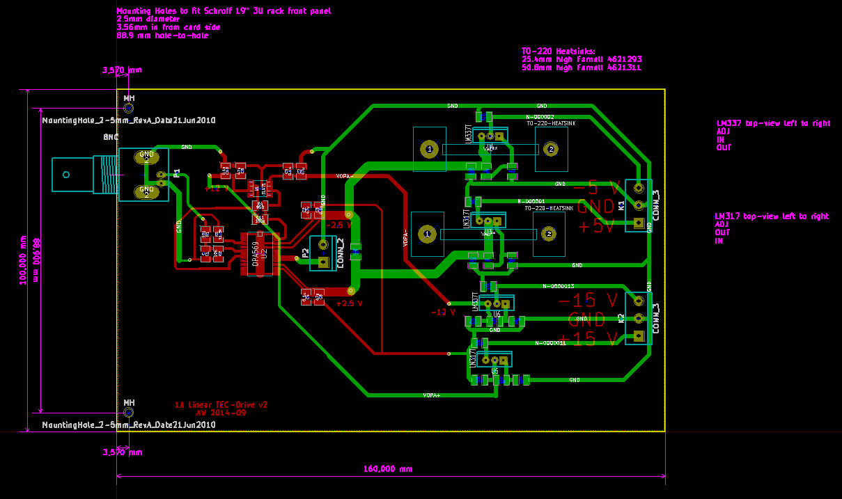
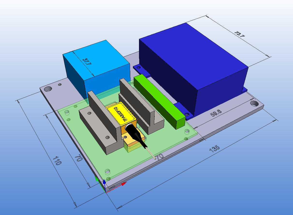
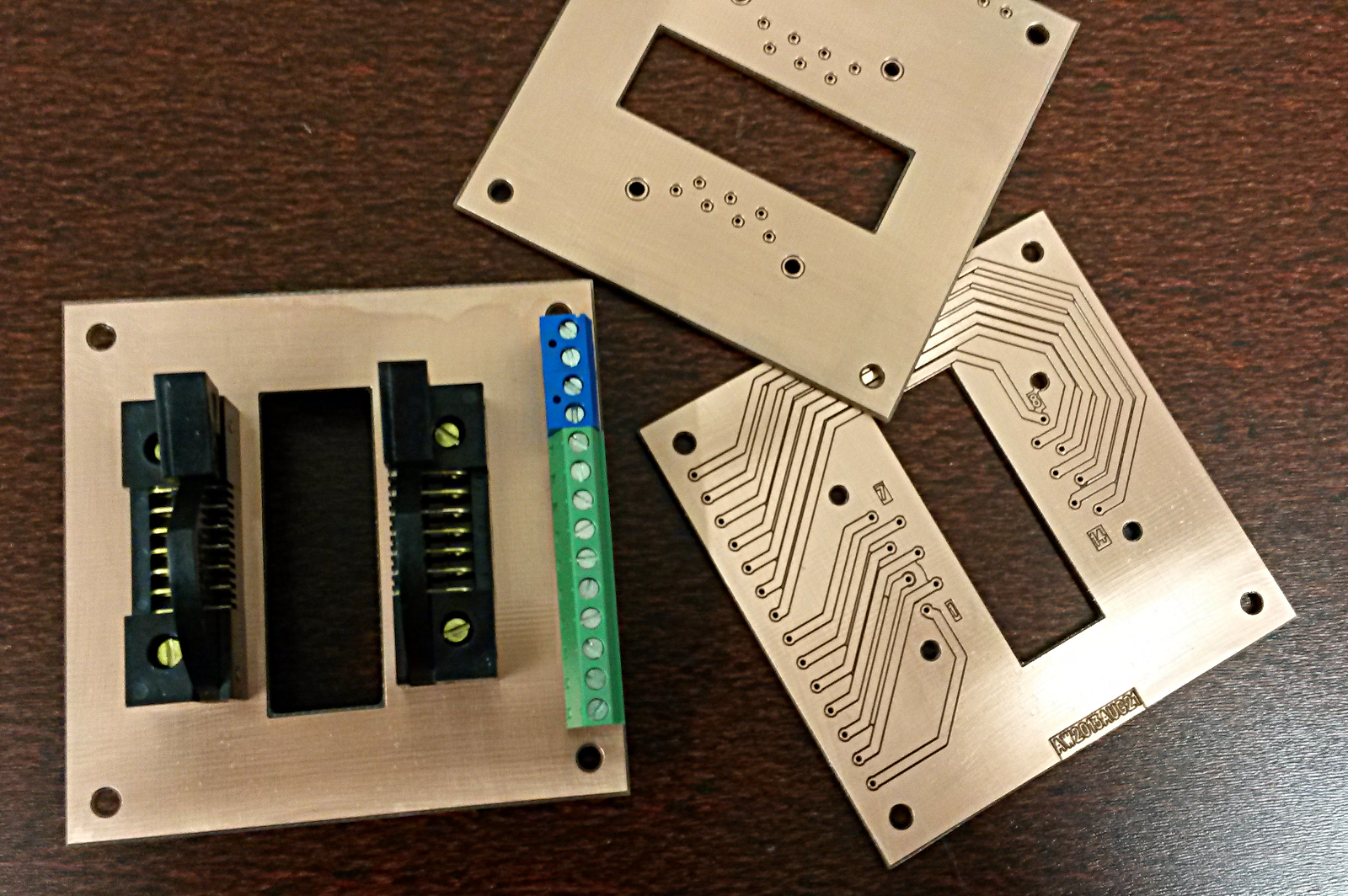
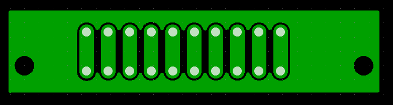
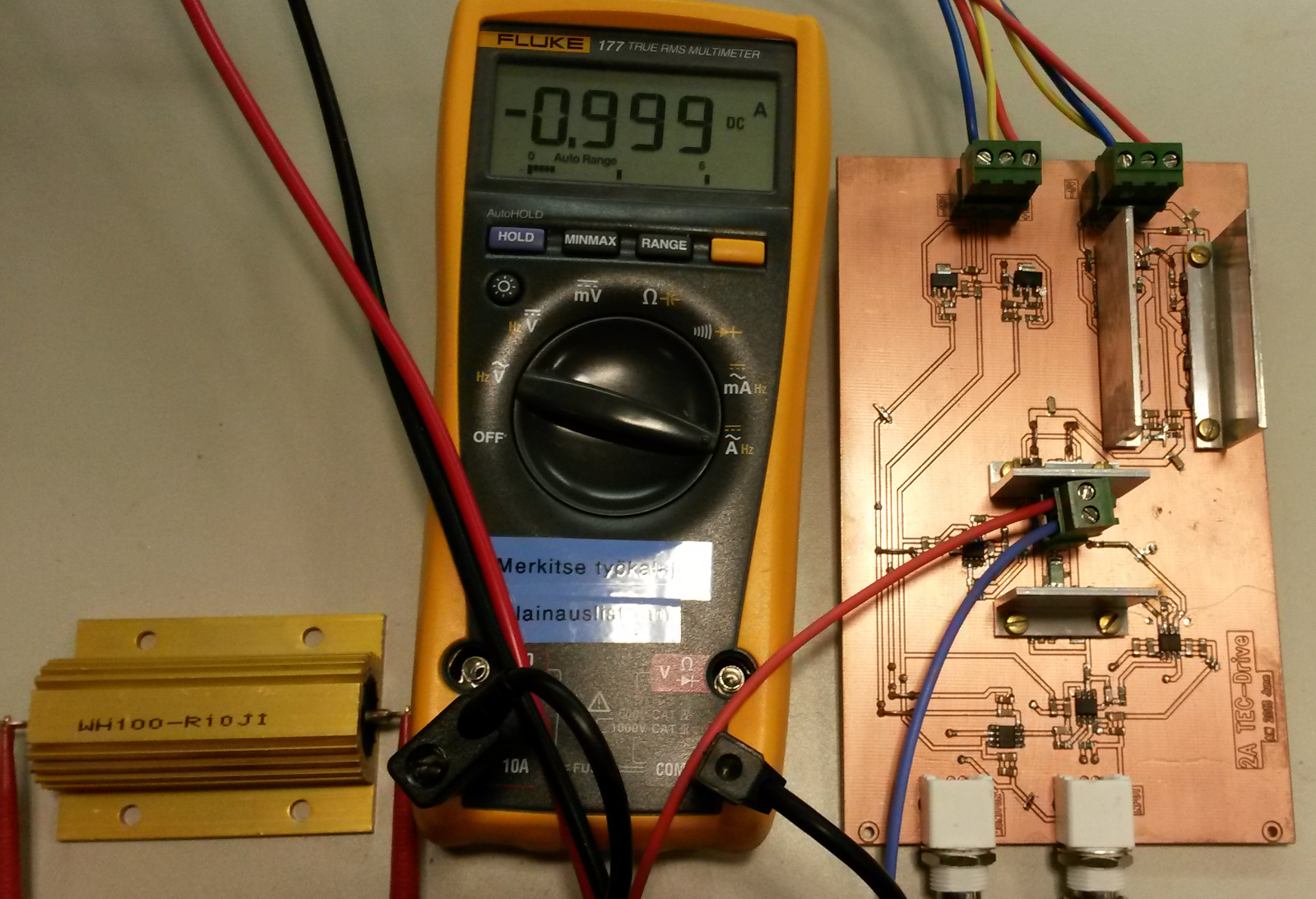
Here's how these things look on the PCB:

tecdrive_drawing

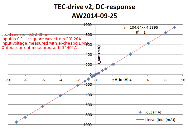
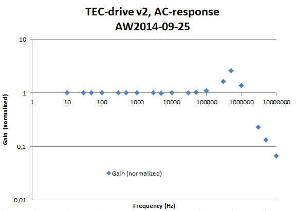
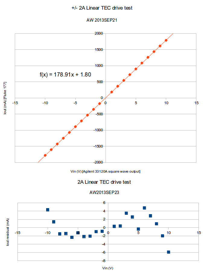
After some assembly, bugfixing, and tweaking I measured a DC transfer function like this:

tec-current_vs_input_voltage_2013aug1

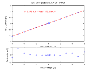
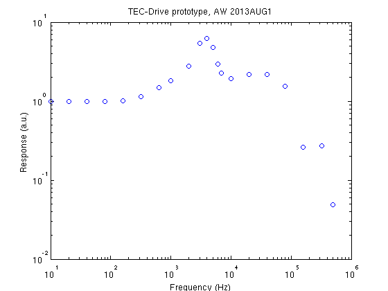
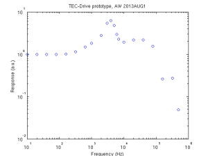
I am happy with the small offset of <0.2 mA and the linearity seems good. There is a rather large gain-error since the design-goal was 200 mA/V and the measured sensitivity is 179 mA/V. The AC frequency response is quite ugly with a high peak at a few kHz. In the time-domain this shows up as severe ringing when driven by a square-wave input. (aside: the SBEA001 application note shows a SPICE-simulated frequency response up to MHz frequencies - theory/simulation and practice differ a lot in this case!).

tec-drive_f-response_2013aug1

Things learned so far:

  • The original design used OPA353 op-amps. I had assumed these will work with bipolar +/-12 V supplies and the output swing would be close to +/-10 V. Not so! (the OPA353 is a single-supply op-amp). I used TL071 op-amps instead and they seem to work.
  • Bypass capacitors close to the collectors of Q1-Q4 are essential (but not shown in the circuit-diagram!). The feedback loop would go mad with oscillations without 1 uF caps placed close to Q1-Q4.
  • Q1-Q4 (and the linear regulators) will require heatsinking for >1 A currents.
  • The current-sensing instrumentation amplifier U3 (I used an AD8221 instead of the INA155 in the application note) is probably the most sensitive part of this circuit. I added 200 Ohm series resistors on the inputs, as well as low-pass filter capacitors (100 nF) to ground on both + and - inputs. This seems to have a calming effect on noise/oscillation of the feedback loop.
  • This kind of push-pull power stage shows significant cross-over distortion when the input signal crosses zero. Here the op-amp that drives the bases of the transistors needs to slew quickly either up or down in order to turn off one transistor and turn on the other one.

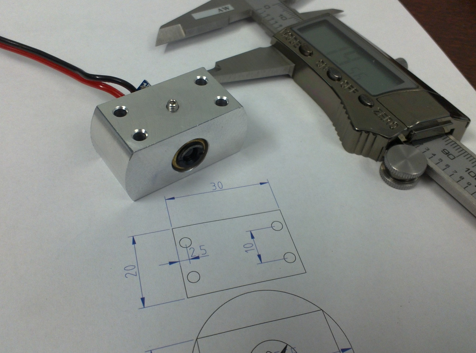
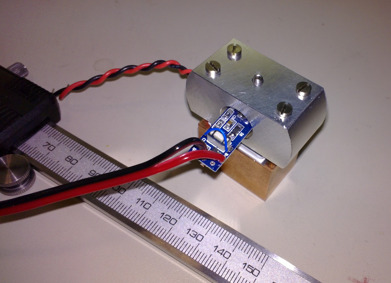
If all goes well this TEC-drive will be part of a temperature control system consisting of about five different PCBs or circuits:

  • Digital controller. Talks over SPI to DAC and ADC cards. Runs PID and/or feed-forward algorithm on real-time OS to keep temperature steady.
  • ADC-Card. Reads +/-10 V input voltage at 24-bit resolution and 1-100 samples/s speed.
  • DAC-Card. Outputs +/-10 V voltages as input to TEC-drive. 1 sample/s speed is sufficient.
  • Temperature-sensor frontend. Converts pt100 (or alternatively 10k NTC) resistance change into +/-10 V output for ADC. Previous blog posts here and here.
  • TEC-Drive (this PCB). Converts +/-10 V input from DAC into a +/-2 A constant current through the TEC.

TEC mount for laser-module

tec_adapter_1

tec_adapter_2

I made this aluminium bit on the lathe/mill today. It holds a blue laser-module from dealextreme. The brass barrel measured about 11.81 to 11.84 mm in diameter so I first drilled a 10mm hole, then opened it up slowly on the lathe until the module just fit the hole. There is an M3 set-screw to hold the laser module in place. Four long M2.5 screws clamp the aluminium part into contact with a peltier-element and the copper heatsink. A thermistor for temperature measurement and feedback control will be glued to the aluminium part as close as possible to the peltier.

Temperature control of the laser diode should provide for rough tuning of the laser wavelength. We want the wavelength to be about 405.2 nm, to be used for photoionization of Strontium.

Aside: A few years ago I tried to order some of these 405nm laser-pointers to the university. It was impossibly difficult because the shipments were stopped by the customs. Negotiations with the radiation-safety authorities did not help. It's simply forbidden to import non CE-approved laser-pointers - it doesn't matter if you are a researcher or work at a research institution. The story is completely different for laser modules (this is exactly the same product as the laser-pointer, but without the pen-like shape and the battery holder). Apparently these are classified just as "diodes" or "electronic components" and there are no problems getting them through customs.