LPKF Protomat S91 PCB-mill

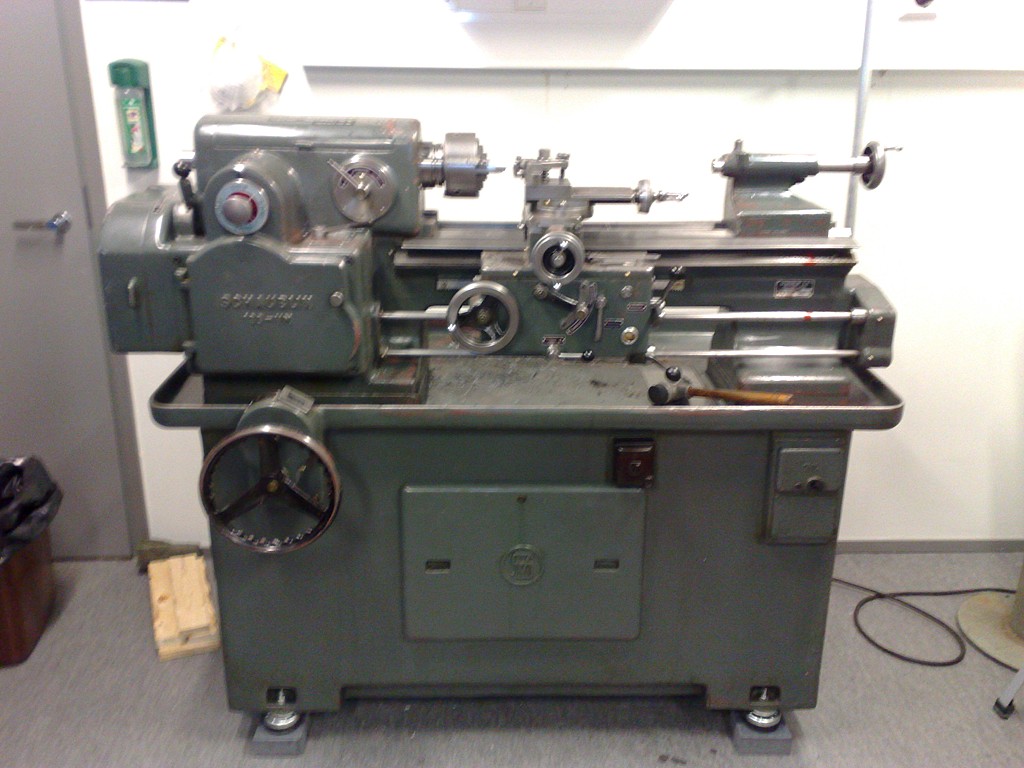
Update: here's a picture of how the original spindle looks like.
lpkf_protomoat_original_spindle

By popular demand, some pictures of the modified LPKF Protomat S91 PCB-mill (featured here). The spindle assembly on this mill has been re-built. The original has an LPKF spindle motor and a solenoid for pushing/pulling the spindle up/down along the Z-axis. This modification uses a Proxxon spindle and an air-cylinder for the Z-movement.

overview 

overview2

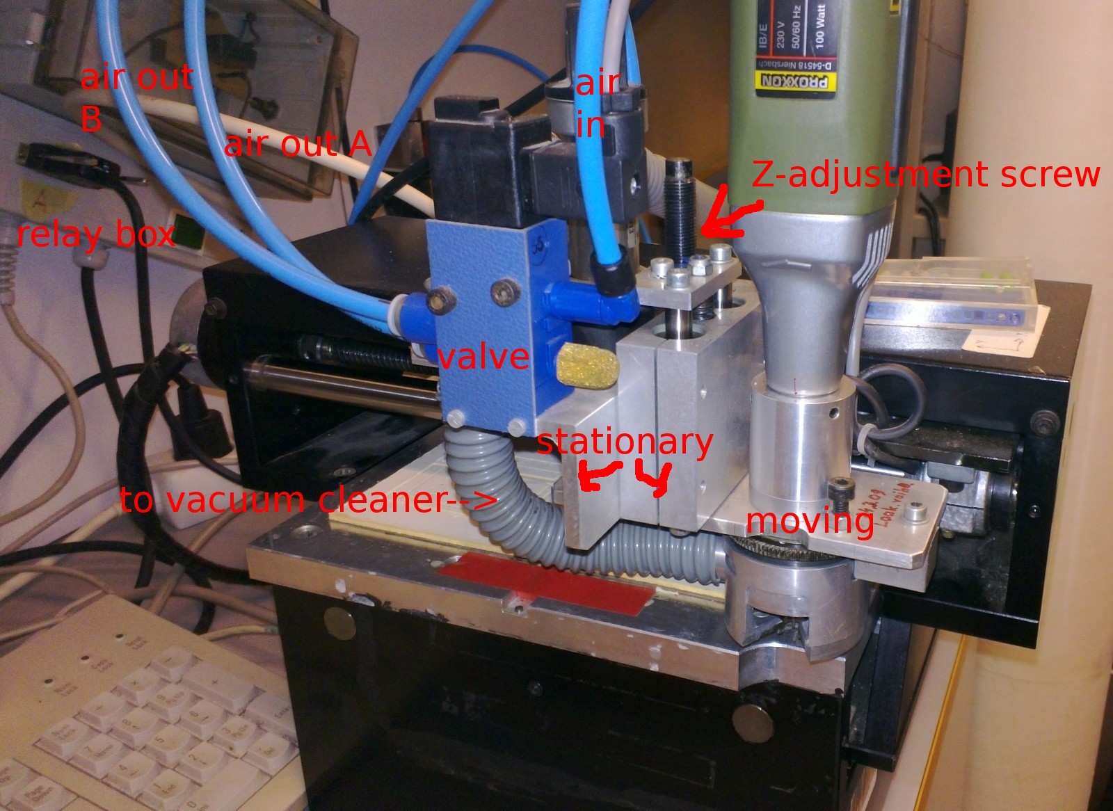
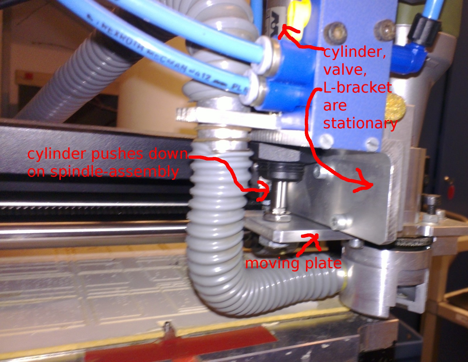
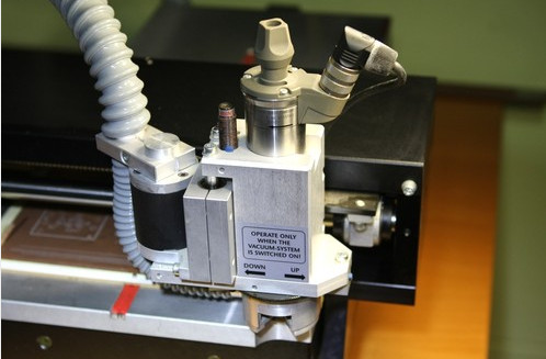
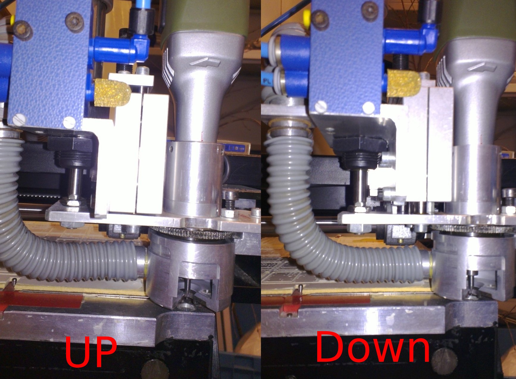
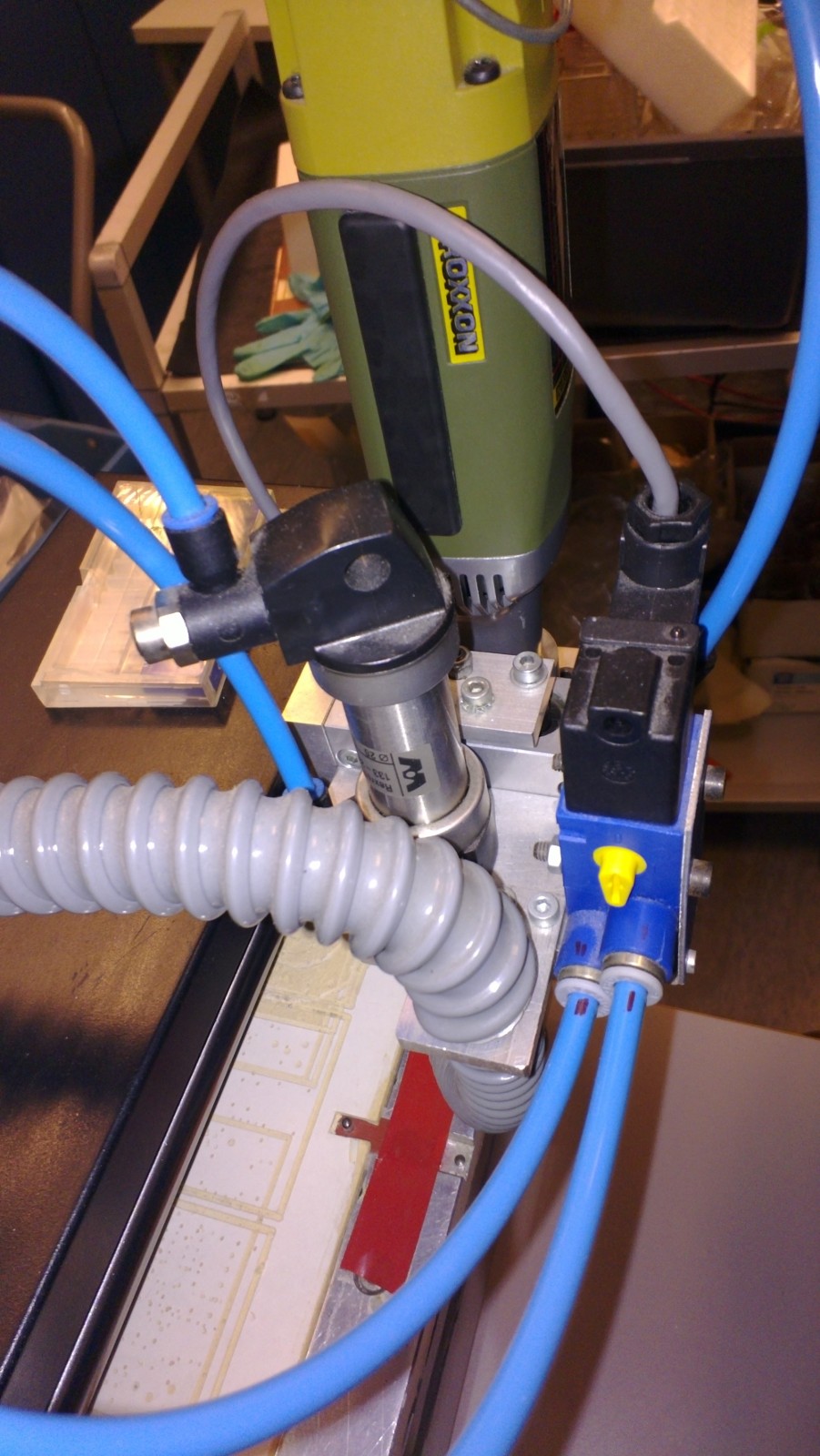
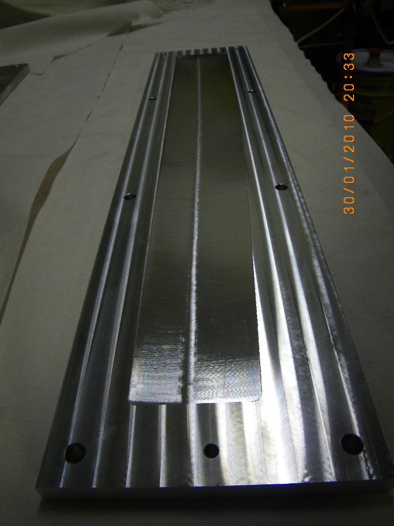
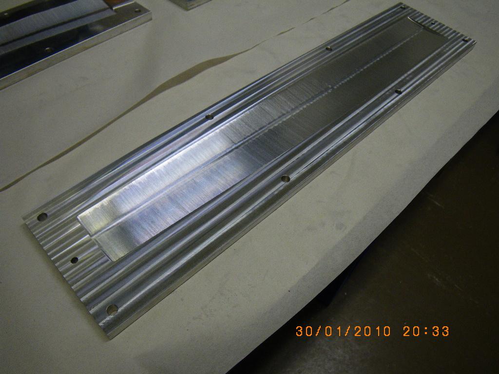
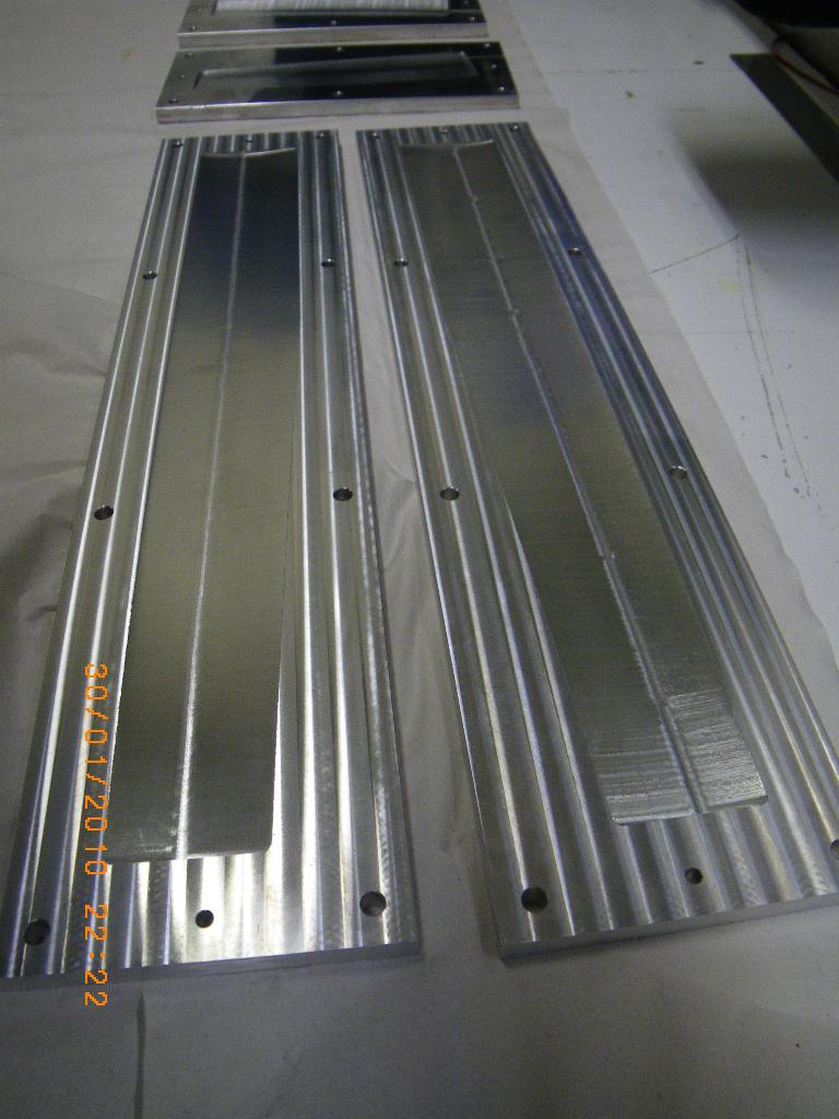
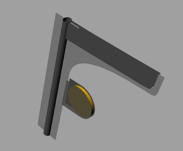
These two pictures shows the spindle from the front. Pressurized air is input to the valve which routes it either to output A or B. This pushes the air cylinder either to the UP or DOWN position. The cylinder pushes on an aluminium plate to which the spindle motor is attached. The moving plate is guided by a linear bearing. A screw at the top of the linear bearing allows adjustment of the Z-depth of the DOWN position. A spring at the top also helps with pushing up the spindle.

cutter


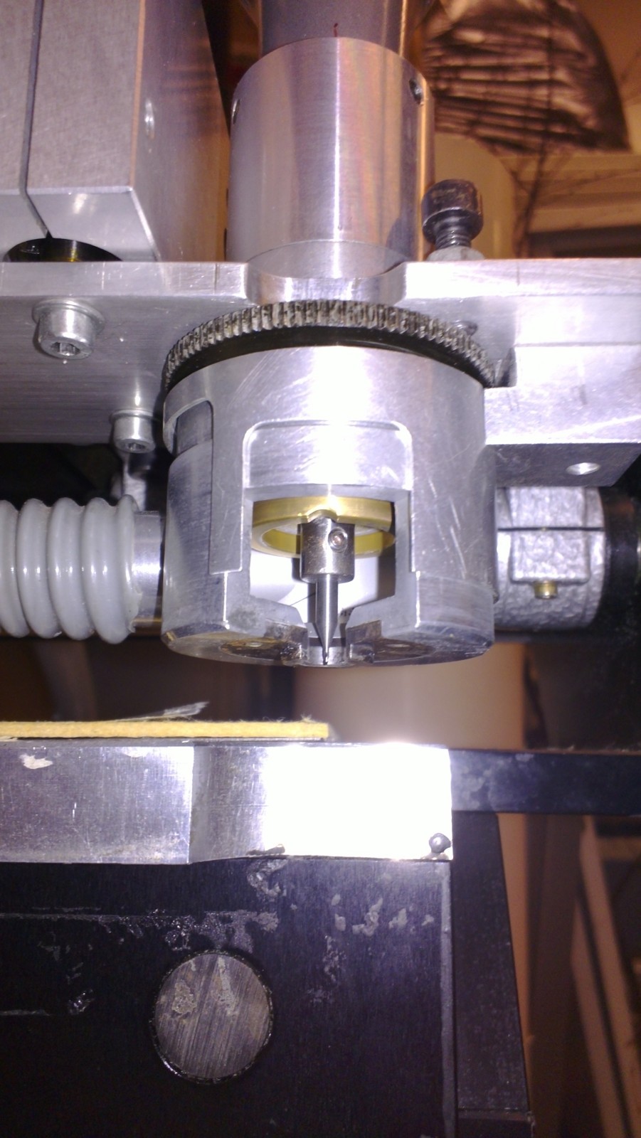
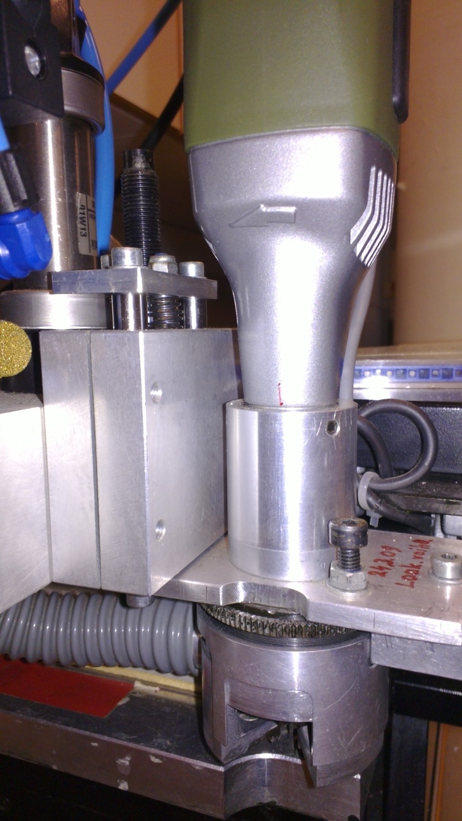
This picture shows the cutter. A vacuum cleaner attaches to they grey tube, and sucks away all chips produced during drilling and milling. A cylindrical cover or "door" around the spindle (now open for tool change) is rotated shut when the machine runs.


connections

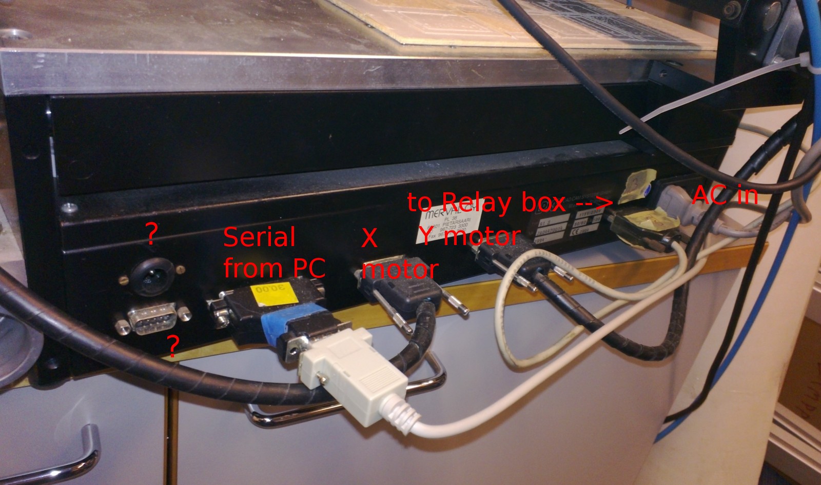
This shows the electrical connections. The modification of the spindle involves connecting a cable from the second connector from the right to a custom-built relay box. Otherwise the connections are as on a standard machine.

relay_box


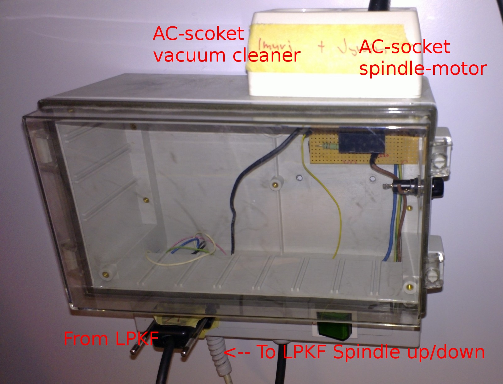
This shows the relay box. The cable from the base of the machine is used to control three On/Off devices: vacuum-cleaner on/off, spindle-motor on/off, and Z-axis up/down. The spindle-motor and vacuum cleaner connect to standard AC-mains sockets. The Z-axis up/down control signal is connected to the air-valve on the spindle assembly.

spindle
up_down

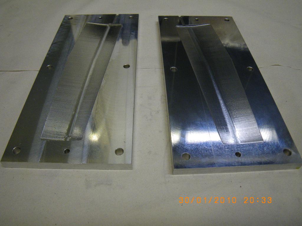
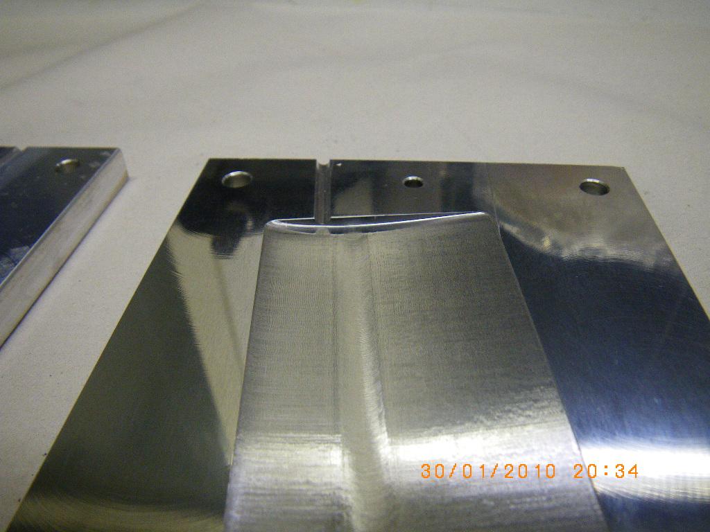
Some additional views. Note how small the required Z-movement is.

z-cylinder
z-cylinder2

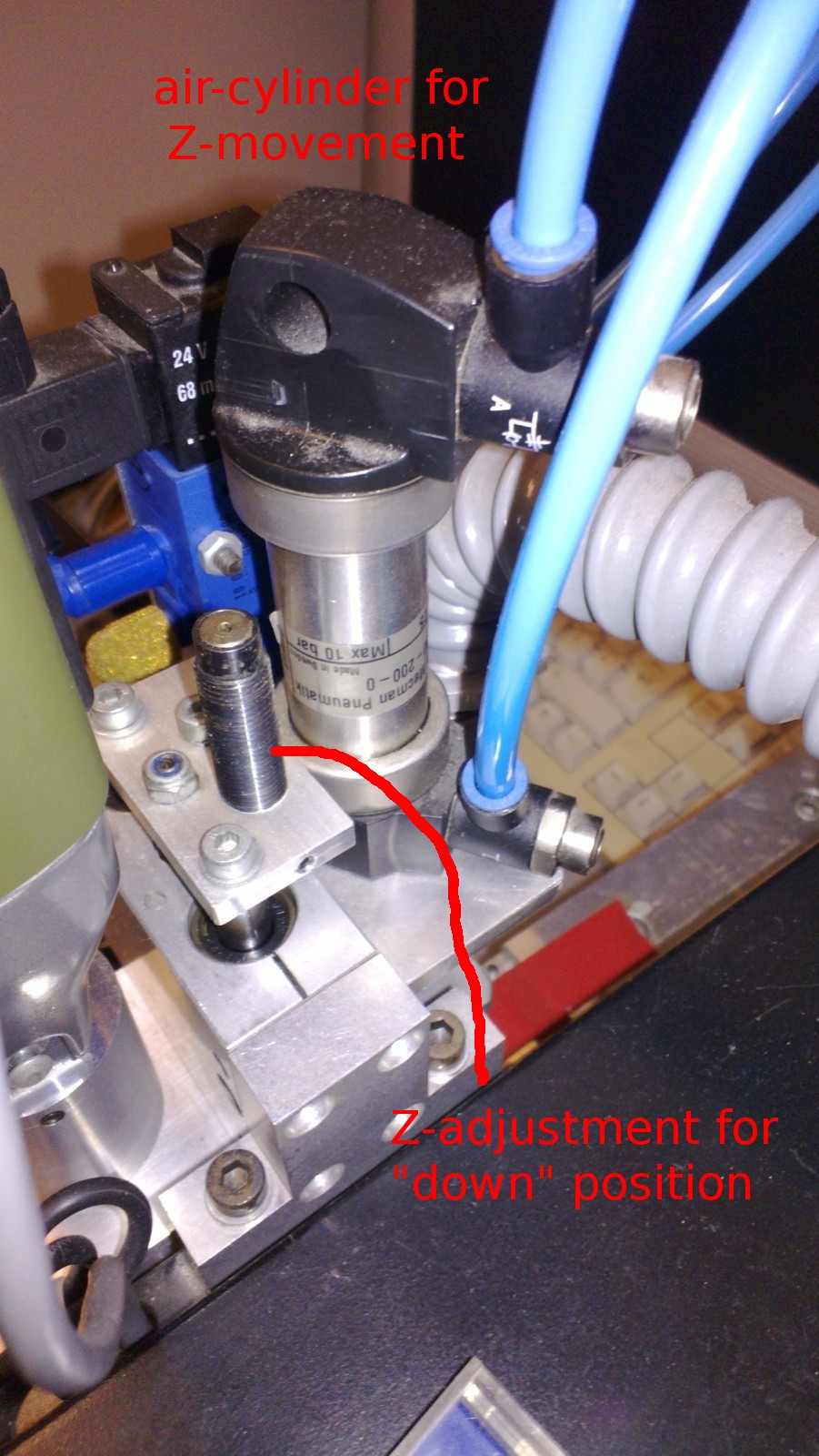
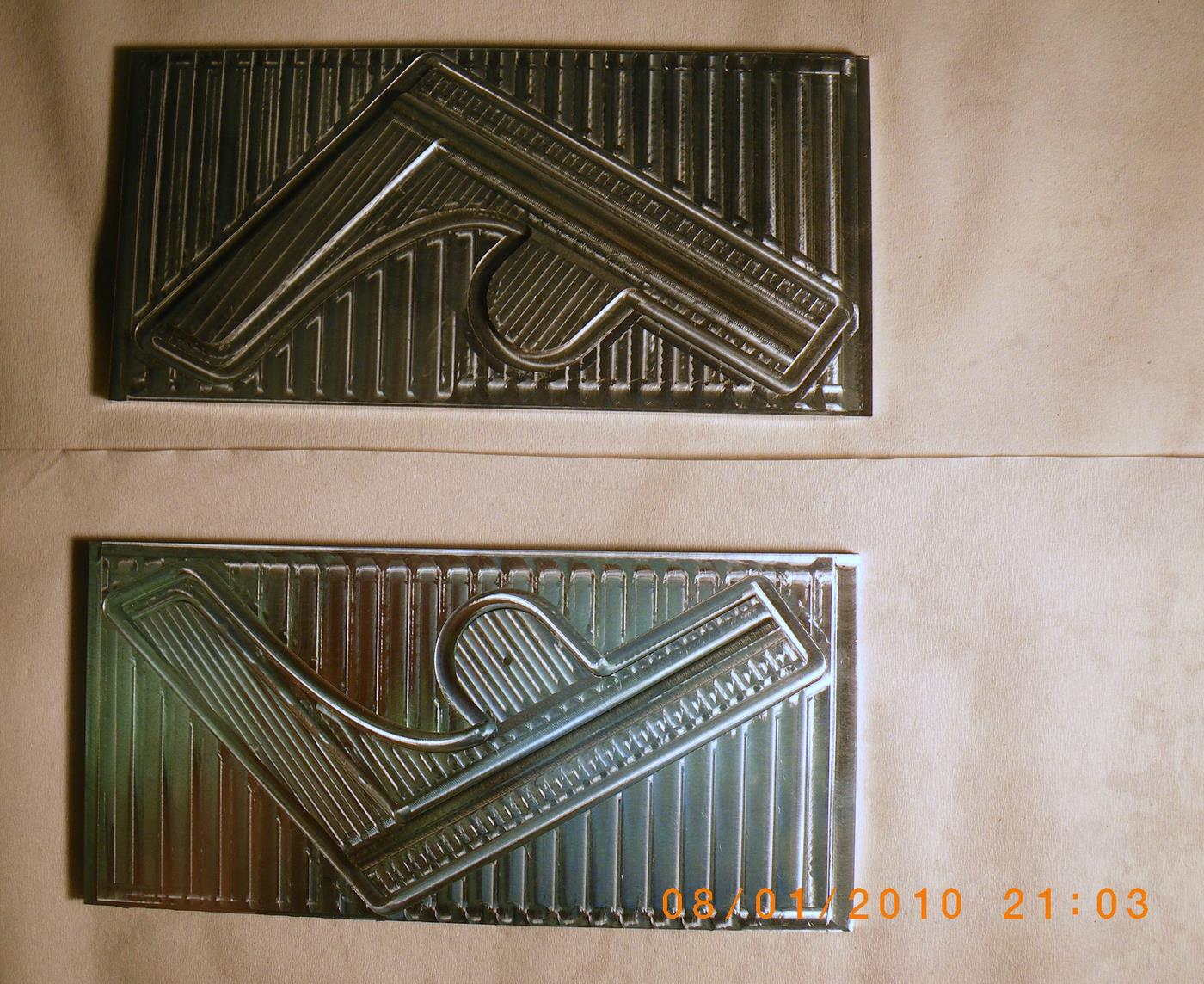
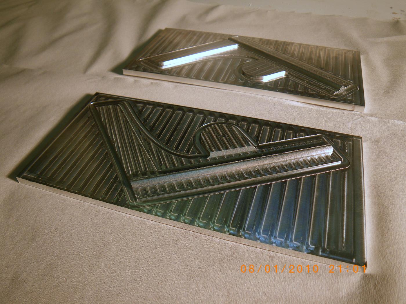
These pictures show the air-cylinder.


PCB Milling

We have a 1994 LPKF Protomat S91 PCB mill in the lab for making prototype PCBs. Here it was used to cut a circular part (not a PCB) which was first drawn in CorelDraw, then saved in HPGL format, and then opened in BoardMaster which is the program that controls the mill through a quirky serial protocol. I think the original LPKF design has a solenoid for the up/down z-movement of the tool. The solenoid would become unreliable during a long run, because it was getting very hot, so on our mill it has been replaced with a more reliable pneumatic cylinder. The spindle is a Proxxon hand-tool, and tool changes are manual.


CNC-turned stainless steel IOM bulb

CNC-turned from stainless steel, this is a 400mm long and 38mm diameter IOM keel bulb. A slot will be milled in the middle for the keel fin. Unlike a lead-bulb this one will require no surface filler/sanding/painting. But the density (compared to water) of stainless steel is 8 at most, while lead bulbs can be close to 11 (depending on the lead-alloy), which means the volume of this bulb is slightly larger.

Steel Fin Moulds

Jari machined these steel fin moulds for the PIKANTO over the weekend. The fin will be moulded with a clear glecoat, one 200g carbon layer as a surface layer, and one 250g/m2 UHM UD carbon layer. We are going to use either cnc-machined balsa cores, or a 2-component epoxy foam core. The bulb attaches with an M3 threaded rod which will be moulded into the lower end of the fin. At the boat end we'll insert a metal piece with M4 threads so the fin can be attached to the boat with an M4 hex screw.

RG65 Fin and Rudder moulds

We've done the CAD design, CAM-toolpaths, and CNC-machining for a set of RG65 model yacht (looks roughly like this) fin and rudder moulds. They will be shipped to the customer on Monday.

From time to time I get enquiries about making moulds like this, for fins, rudders, bulbs, etc., from people around the world. Usually by people who've gone to a professional mould-shop or cnc-workshop with their drawings, and suffered a bit of sticker-shock when they've seen the quote. For this set of moulds we asked 500 euros, which is not a lot I claim. Production and delivery in one week or less after the final CAD-drawings were available.

If you're interested in CNC-cut moulds in aluminium or steel, please send your ideas, preferably a CAD drawing, and I'll send you a rough quote. Keep in mind that our machine has a working XY envelope of ca 500x200 mm, so no single parts can be bigger than this. There are lots of examples of what we do in this blog, you might like: bumper mould (2010 Jan), Rudder mould (2009 Dec), IOM MDF plug (2009 Feb), Microscope part (2009 Sep), IOM Fin moulds (2008 Jun), Telescope rings (2008 May).

Jib support mould

fokkatuki
This jib-support part which goes into the bow of the boat has about three or four different purposes. First, it stiffens the forward deck to take the loads from the rig, second it provides a 6 mm i.d. tube for a dyneema-thread type no1 rig swivel, third it provides a 3mm wide slot for recessed steel pins for the no2 and no3 jibs, and fourth it holds a block for the sheeting system. Here I'm trying a home-made block made from a 24 mm diameter 3 mm wide acetal-wheel (yellow) which is designed to rotate around an M2 bolt through the sides of the shaped jib-support.

Lester Gilbert's PIKANTO-page has pictures of how the SAILSetc equivalent parts look like. With an RMG winch there is no need for the 1:2-gearing in the sheeting-system, and a block is placed at the very front of the boat (see SAILSetc part 67RMG).

SAILSetc has a downloadable drawing with the sheeting systems: http://sailsetc.com/downloads/2006/67G.pdf

Jari has cnc-milled the positive moulds for this part:

IMGP1913-1
Stock is a 200 mm length of 100 x 10 mm aluminium bar. There's a  2 mm hole in the moulds for the block-axle.

IMGP1909-1

Next follows the negative moulds.

Lathe electronics

IMG_0764

Most of the electronics I've ordered for the lathe has arrived by now. Still waiting for the servo-drive for the main spindle.

Bottom left are three switched-mode power supplies: 5V 3.5A (logic etc), 12V 3.3A (brushless amps, E-stop chain, etc), 24V 1.3A (spindle brake)

Bottom right are two Chinese 350W 48VDC 7.3A power supplies for the X- and Z- servos. Bought on e-bay from one of the Chinese sellers that has free worldwide shipping, and these were not caught by the local customs, so I paid around 28 euros/supply!

Mid row: on the left a Siemens Micromaster 420 0.37 kW VFD which will be used for a future live-tool spindle, and on the right two pico-systems brushless servo-amps.

Top: limit switches, Mesa 5I20 PCI-card, 180W Brushless servos for X and Z, CUI encoders, Amphenol connectors.