Steel Fin Moulds

Jari machined these steel fin moulds for the PIKANTO over the weekend. The fin will be moulded with a clear glecoat, one 200g carbon layer as a surface layer, and one 250g/m2 UHM UD carbon layer. We are going to use either cnc-machined balsa cores, or a 2-component epoxy foam core. The bulb attaches with an M3 threaded rod which will be moulded into the lower end of the fin. At the boat end we'll insert a metal piece with M4 threads so the fin can be attached to the boat with an M4 hex screw.

Building Bow Bumpers

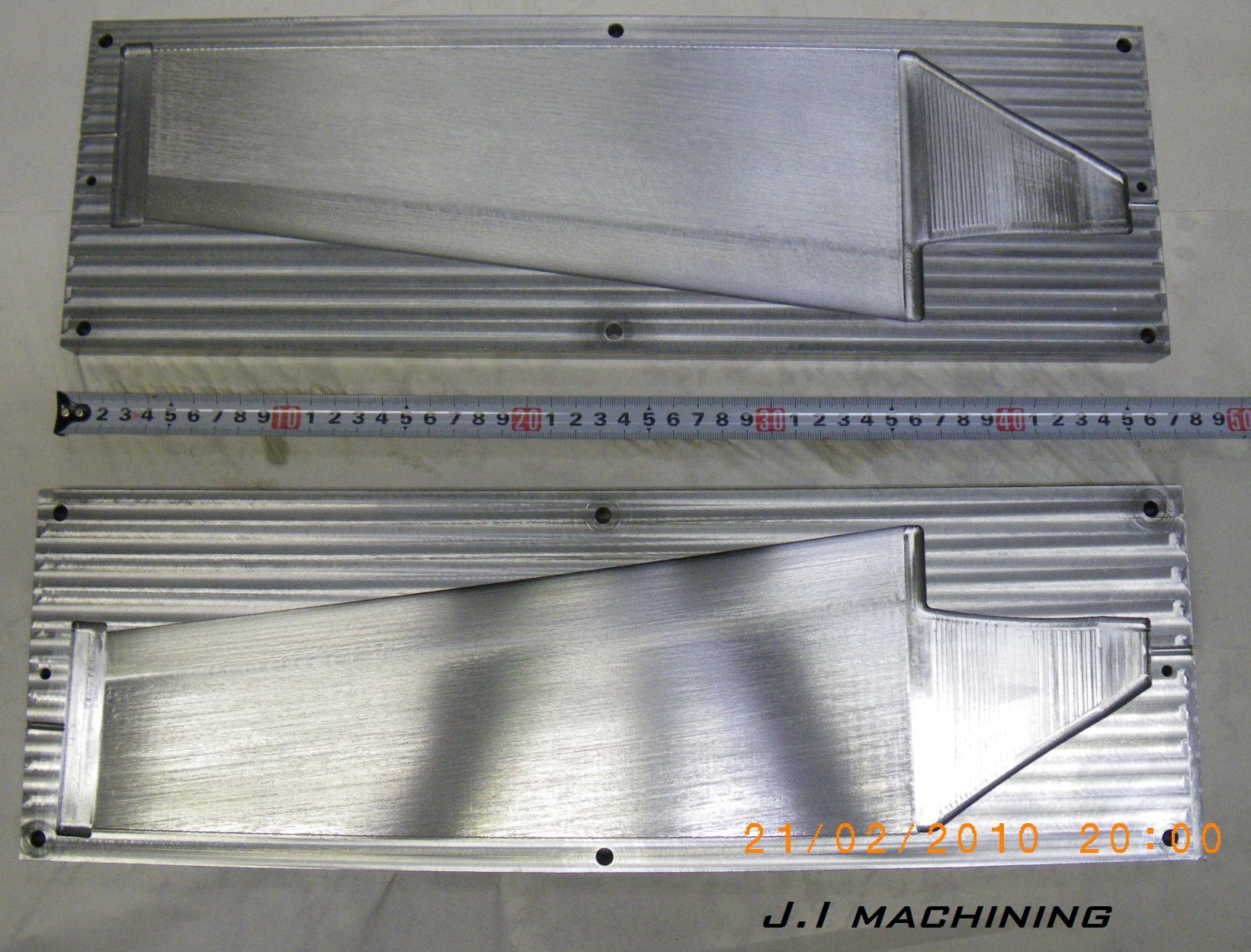
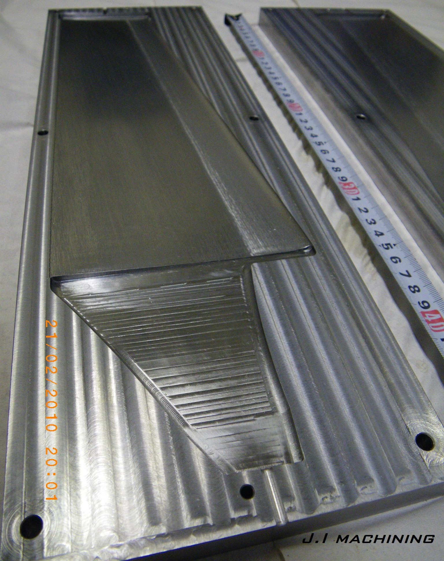
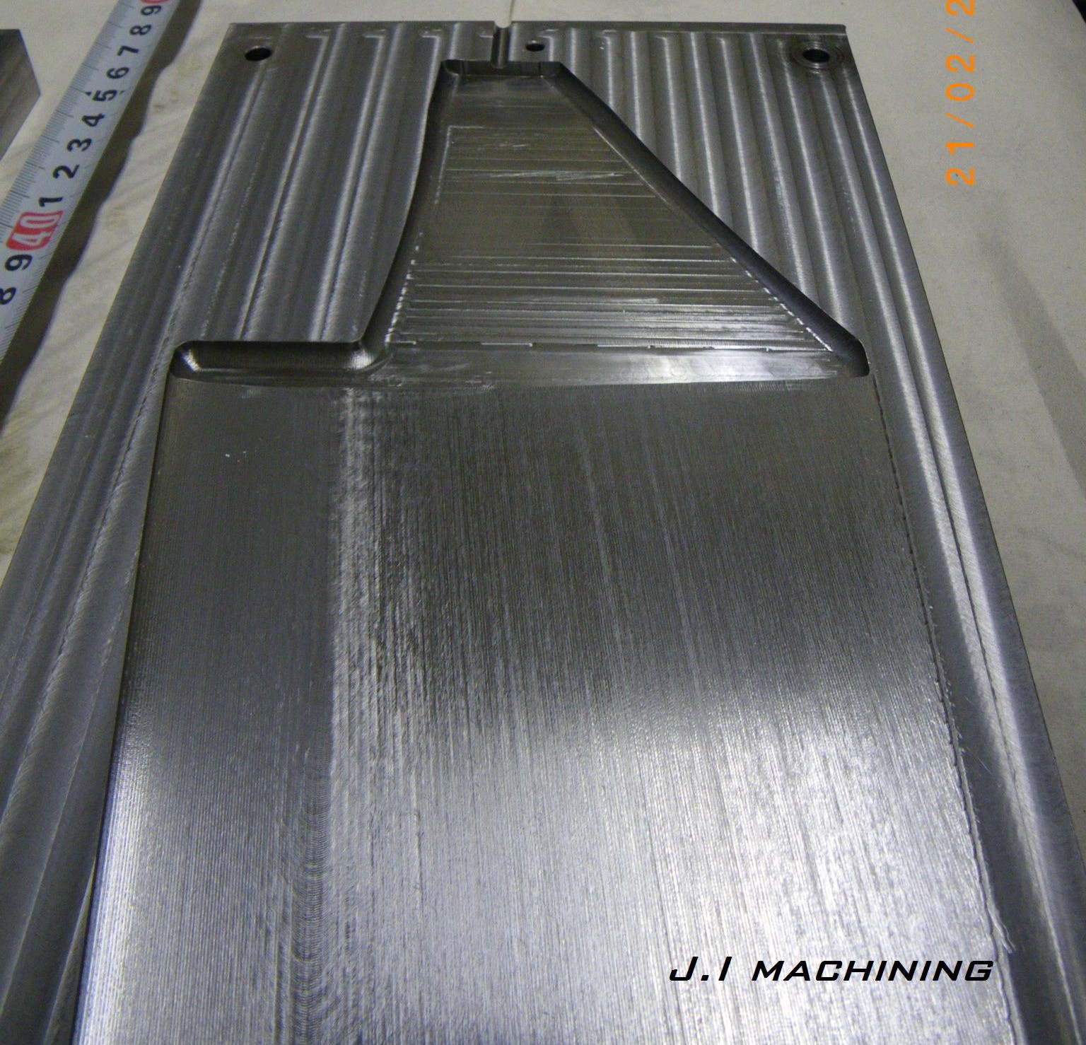
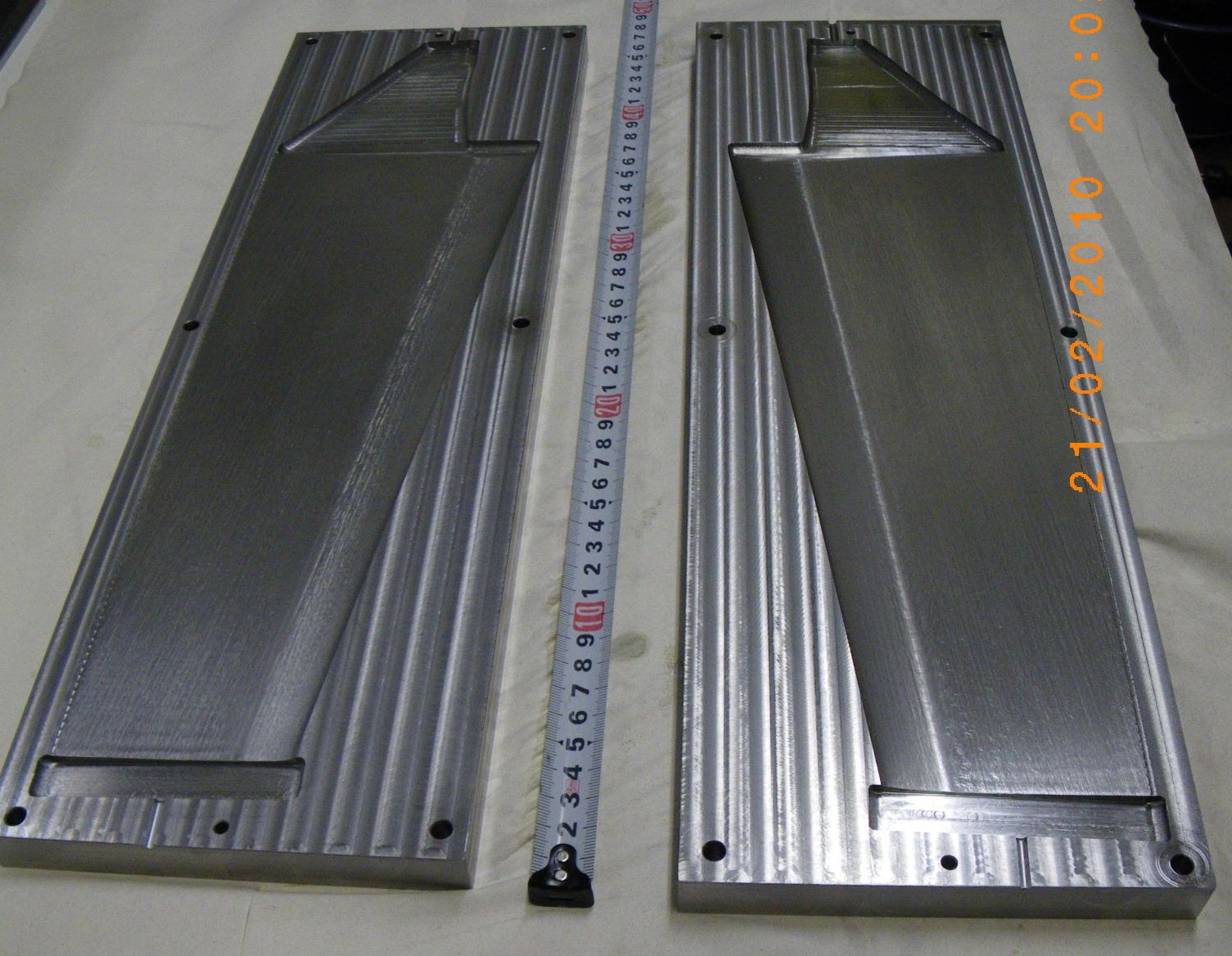
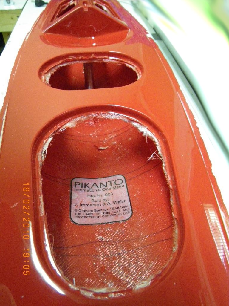
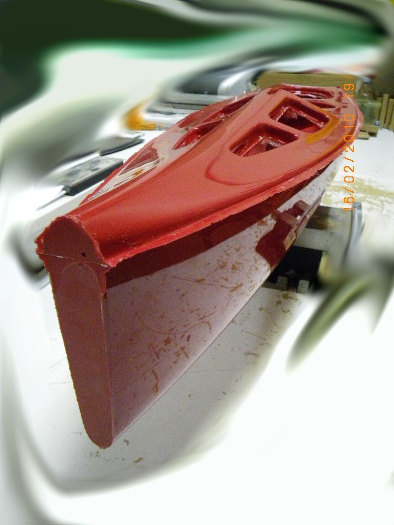
Most model-yacht classes require a soft bow-bumper to be installed on the bow of the boat, to prevent serious damage when the inevitable collisions happen.

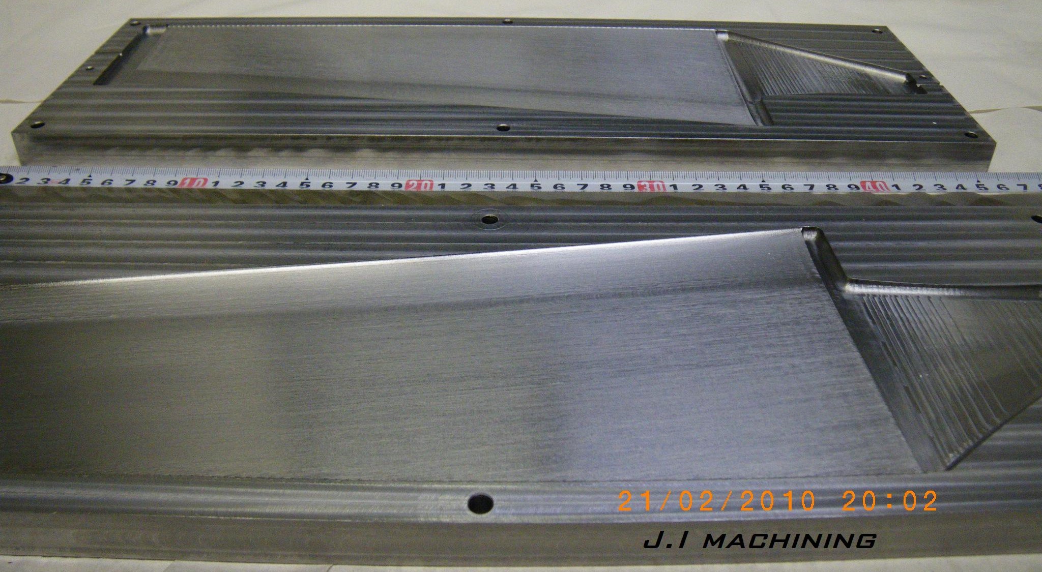
We milled a bow-bumper mould for the PIKANTO a while back. A first test was made using the normal Frekote+wax release agent (which we use when moulding boats with epoxy+glassfiber) in this mould and a standard bathroom silicone. Not very successful. The silicone stuck to the mould, cured slowly, etc.

Googling for this a bit it seems there are separate release agents made for silicone-casting. The simplest solution I found was to use Vaseline (a.k.a. petroleum jelly). This can be diluted in some hydrocarbon solvent to make a thinner Vaseline release-agent.

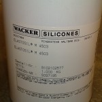
We've used RTV-615, a two-component silicone, previously in the lab for various projects, so I decided to try it for bumpers also. It looks like this, and is mixed in a 10:1 (A:B) ratio.

The closest thing to Vaseline I found lying around was this High-vacuum grease, which I applied to the moulds undiluted. In the future it's probably better to dilute it a bit to get a thinner mix and a thinner coat of release-agent on the mould surface.

I mixed 22 ml of the RTV-615 (a transparent liquid), added about three tea-spoons of white microballoons to produce a thick white mix, and poured this into the mould. At room temperature the RTV-615 cures in about 6-7 days (!), which is clearly too slow for me. However, at +100 C the curing time is reduced to just one hour. After an hour in the oven the bumper felt fully cured, and released from the 2-part mould by applying light pressure. Voila!

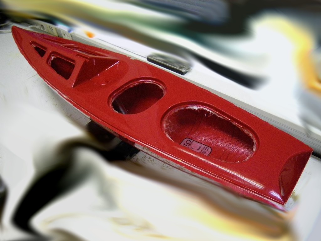
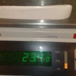
The bumper looks good without any major air-bubbles visible, and weighs about 16 grams (never mind the decimals 🙂 ).

I would be interested in hearing about how other builders make bow bumpers. Anyone know where to order some RTV-615? Use the Add Comment link above!

Pikanto hull nr 3

Our third PIKANTO hull, a.k.a. "Yellow Submarine" was taken out of the mould today. As expected, the yellow gelcoat doesn't cover very well which gives the boat a very "prototype" and/or "artsy" look 🙂

I used a dremel with a cutting-wheel to cut off the extra glassfiber from the deck openings, and then a sharp knife and sandpaper to finish the join between the hull halves and between the deck and the hull.

For various reasons it seems hulls nr1 and nr2 will be demo-boats, and nr3 will be the first one to sail. Weight is slightly more than before, 620 g. As predicted, by hull nr 5 or so we will have mastered at least the basics of how to produce nice looking strong and light hulls from these moulds.

Yellow Submarine

We are finding that different colour pastes result in gelcoats with widely different ability to cover and produce a nice finish. This means we'll have to do a bit of experimenting and then only produce boats with colours that are easy to work with.

Hull nr. 3 "Yellow Submarine" was moulded last weekend and it will be interesting to see the result. Against the black of the mould-gelcoat the yellow doesn't seem to cover too well (compare to hulls 1 "sky-blue" and 2 "battleship-grey").

These pictures are taken just after painting the gelcoat into the mould. We make the gelcoat from the moulding-resin by adding colloidal silica and the colour paste.

Making hull nr3 was a 7 hour process:

10:00 arrive at workshop, do a bit of cleaning and preparation
11:00 start mixing and applying gelcoat to moulds, takes about an hour for deck and hull.
12:00 - 14:00 wait... gelcoat is in the mould and needs to cure. not much to do now(eat lunch, cut fibers, etc).
14:00 start moulding. The hull is fairly quick and only takes an hour or so
15:00 mould deck. This is more tricky with a lot of different small bits of fibers required, takes more than an hour usually
~16:00 fibers are in both moulds, close the moulds and start on the join between deck and hull
17:00 all done. Leave moulds and new boat to cure.

Mast partner

Update: here is Jari's "fork" design for the mast-partner:

The forward hole could be made a bit bigger so a 4mm acetal-rod with a small central hole for the jib-sheet will fit. There could be an M3 or M4 threaded hole added for the mast-ram, and finally some holes for a U-shaped bent wire which forms a deck-eye through which the no3 jib is sheeted.

Here's the glassfiber version I was first thinking about:

The way we mould the deck and hull in one go we don't get an overhanging foredeck which would support the mast. One solution is this kind of "mast partner" which is glued/bolted to the foredeck and provides sideways support for the mast. If the slot is made say 16 mm wide the mast will need a sleeve of metal/plastic that fits this 16 mm slot accurately. There is room for a ca 18-19 mm diameter thumbwheel(red) on the mast ram.

Here's a photo of a SAILSetc 10R (or M?) which uses this idea:

Radio install idea v3

radio
Here's another idea for the PIKANTO radio-installation. The yellow parts are 1.5 mm glassfiber boards (PCB-material) which are glued to the finbox and the mainsheet post. They would provide two or four mounting holes for M3 bolts that secure the main radio-plate (not shown) to the boat. If this is rigid enough I think no support to the sides of the hull or to the deck is required.

Jib support mould

fokkatuki
This jib-support part which goes into the bow of the boat has about three or four different purposes. First, it stiffens the forward deck to take the loads from the rig, second it provides a 6 mm i.d. tube for a dyneema-thread type no1 rig swivel, third it provides a 3mm wide slot for recessed steel pins for the no2 and no3 jibs, and fourth it holds a block for the sheeting system. Here I'm trying a home-made block made from a 24 mm diameter 3 mm wide acetal-wheel (yellow) which is designed to rotate around an M2 bolt through the sides of the shaped jib-support.

Lester Gilbert's PIKANTO-page has pictures of how the SAILSetc equivalent parts look like. With an RMG winch there is no need for the 1:2-gearing in the sheeting-system, and a block is placed at the very front of the boat (see SAILSetc part 67RMG).

SAILSetc has a downloadable drawing with the sheeting systems: http://sailsetc.com/downloads/2006/67G.pdf

Jari has cnc-milled the positive moulds for this part:

IMGP1913-1
Stock is a 200 mm length of 100 x 10 mm aluminium bar. There's a  2 mm hole in the moulds for the block-axle.

IMGP1909-1

Next follows the negative moulds.